AIRBEAM TECHNOLOGY PowerPoint PPT Presentation
1 / 29
Title: AIRBEAM TECHNOLOGY
1
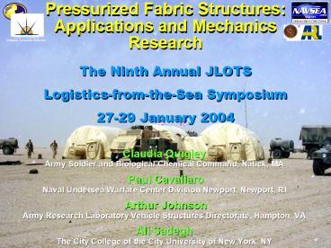
Pressurized Fabric Structures
Applications and Mechanics Research
Center of Excellence Inflatable Composite Structu
res
The Ninth Annual JLOTS Logistics-from-the-Sea Sym
posium
27-29 January 2004
Claudia Quigley Army Soldier and Biological Chemi
cal Command, Natick, MA Paul Cavallaro Naval
Undersea Warfare Center Division Newport,
Newport, RI Arthur Johnson Army Research Labo
ratory Vehicle Structures Directorate, Hampton,
VA Ali Sadegh The City College of the City Uni
versity of New York, NY
2
Airbeam Technology
- Load Bearing Pressurized Fabric Structures
- Pressurization pre-tensions the fibers, creating
a structure that is rigid under design loads, but
deflects without damage when overloaded. - Achieves outstanding strength-to- weight ratios.
3
Shelter Technology
- Replace metal structural frame shelters with
inflatable arches or airbeams to provide - Rapid, Easy Deployment
- Reduce Weight
- Low Cube
- Available in widths ranging from 20 feet to 85
feet for applications such as command/control,
medical, vehicle/aircraft maintenance
4
Manufacturing Technology
- Two new textile technologies produce seamless
tubular braided or woven fabrics with high
pressure capacity (30-80 psi) - Curvature and bending resistance are obtained by
using coated high-tenacity fibers and controlling
fiber orientation.
5
Center of ExcellenceInflatable Composite
Structures
(Established in 2001 at the Natick Soldier Center
in Natick, MA)
- Increase durability, reliability and
affordability
Market and Document Technology
Establish predictive design tools and models
Broaden inflatable structure applications and com
mercialize
the technology
Partner with DoD and government agencies, indu
stry, and academia
Vision Deliver new shelter technology into th
e hands of soldiers and commercial users.
6
New Shelter Technology
- Future Medical Shelter System
- 4 Airbeams, 14 inches in diameter
- Internal Air Beam Pressure 60 psi
- Clear Floor Area 1750 sq. ft.
- Deployment Time 20 minutes
7
Rapid Inflation System for Airbeam Shelters
Successfully Tested Prototypes
Objective MET Increase capacity, by a factor of
five, over commercially available, portable air
compressors, through the use of innovative
engineering design, lightweight materials, and
high-speed components
Oil-flooded Screw Compressor
Oil-free Scroll Compressor
Oil-free Wobble Piston Compressor
8
Durability, Reliability, Affordability
- Durable
- Puncture and Small Arms
- Resistant
- Reliable
- Pressure Check Weekly
- Affordable
- New Manufacturing Technology
- Achieved Significant Cost
- Reduction
Aviation Inflatable Maintenance Shelter
at Holloman AFB
9
Broaden Applications
- Army
- Extended Range Aerial Delivery System (ERADS)
- Remote controlled glider
- that delivers cargo to
- troops on the ground
10
Broaden ApplicationsExtended Range Aerial
Delivery System
Configuration in aircraft (Pre-deployment)
Inflatable tubes form the wing
11
Broaden Applications
- Inflatable Ladder
- Weighs 55 lbs
- Inflation Pressure of 40 psi
12
Broaden Applications
- NASA
- Quickly Deployable Space Structures
- Inflatable Boom on a Solar Sail
- Inflatable Telescopes
13
Commercialize the TechnologyAir Beam Shelter in
Production
- Chemical Biological Protection Shelter (CBPS)
- 64 currently deployed in Iraq
Federal Fabrics Fibers, Lowell, MA
Designed Produces Airbeam Frames
Saint - Gobain, Merrimack, NH Designed Pro
duces - Softwall Shelter
14
Air Beam Structural Design
- DETERMINE
- Air beams / arches
- Diameter
- Safe operating pressure
- Warp weft tows per unit length
- Fiber material(s)
- Coating material
- Acceptable Failure Modes
- GIVEN
- Floor length width
- Minimum height requirement
- Environmental Loadings
ARCHES
15
Predictive Tools for Structural Analysis
- Dual Approach
- Predict Structural Response of Air Beam (Wind
and Snow Loads) - Predict Material Behavior
- Fabric Inflated Fabric
Load
16
Structural Analysis
17
Modeling Airbeam Structures
- Modeling Goals
- Develop 3D Braiding Weaving Models
- Scalable Verification Instrument
- Collect and Analyze Empirical Test Data
- Create Integrated Analytical Tool Set
- Advantages
- Analyze Design Problems
- Technology Investment
- Optimize Production
18
Element Assumptions and Formulation
- A specialized structural air beam element for
inflatable structures - Nonlinear fabric mechanics
- Modeling work done by inflation pressure
- Need to predict folding and wrinkling of fabric
- Ease of use when modeling a fabric shelter
Nastran Model
19
4-Pt. Flexure Tests on WovenVectran Air Beams
- Construction Details
- 3000 denier Vectran
- 13 warps/inch
- 13 wefts/inch
- StrengthVectran 28 gpd
- Bladder Estane 58315 TPU
- Bladderthick 0.008
- Uncoated
- End Cap Stitched-on
- Mfg. by Federal Fabrics/Fibers, Lowell MA
- Diameter 6 in Length 8 ft
4-Point Bend Fixture Mounted in Instron? with
Displacement Wire Transducer Used To Capture
Mid-Span Deflection (5 oz. constant tension force)
20
Comparison of Finite Element and Experimental Re
sults
6 Inch Diameter, 37 Inch Load Span
150
Pressurized beam theory
42 psi
Straight lines (typ)
Measured
32 psi
Curved lines (typ)
100
Total Load (Lbs)
22 psi
50
12 psi
0
0
0.5
1
1.5
2
2.5
3
Displacement (inches)
21
Fabric Mechanics Modeling
22
Invariance of Fabric Elastic Stiffness with Tow
Modulus
Breaking Load
III Tow Extension Region
Axial Load
Range of Operating Pressure Loads for Woven Air
Beams
II Decrimping Region
I Inter-Fiber Friction Region
Axial Displacement
See Hearle, J.W.S. et-al., Structural Mechanics
of Fibers, Yarns and Fabrics, Vol. I, 1969 Wiley
Sons, NY., p. 340.
23
Fabric Strip Model Description
21 TDR
- ABAQUS Finite Element Analysis Software
- Full surface-to-surface contact of all tows
- Typical run times 3-4 hrs.
24
Pressure Load Dependent Shear Modulus
TF r
Tow Jamming Region? (Pressure Invariant)
(21 TDR, 11 Equi-Biaxial Loading Ratio With
Hoop Tow Spacing 0.0472)
25
Stages of Pure Shearing Deformations
26
Fabric Elastic Modulus As Functions of Pressure
TDR
EVECTRAN
27
Summary
- Inflated structures are
- - proven to be durable and reliable
- - more affordable
- (Cost reduction is an ongoing process.)
- - sustaining our troops in Iraq
- Modeling efforts predict structural behavior and
inflated fabric properties. - Experimental validation efforts are underway.
28
Yankee Scientific, Inc.
City College CUNY, NY
Center of Excellence Inflatable Composite Structu
res
Federal Fabrics-Fibers, Inc.
29
(No Transcript)

