
Absolute, Differential And Gauge Pressure Transmitter For Remote Seals - PPT PowerPoint PPT Presentation
Title: Absolute, Differential And Gauge Pressure Transmitter For Remote Seals - PPT
1
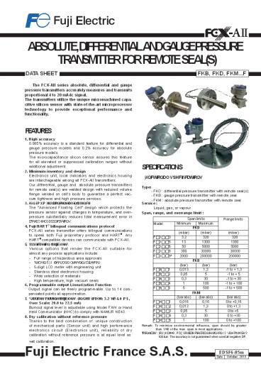
ABSOLUTE, DIFFERENTIAL AND GAUGE PRESSURE
TRANSMITTER FOR REMOTE SEAL(S)
DATA SHEET
FKB, FKD, FKM...F
The FCX-AII series absolute, differential and
gauge pressure transmitters accurately measures
and transmits proportional 4 to 20 mAdc
signal. The transmitters utilize the unique
micromachined capa- citive silicon sensor with
state-of-the-art microprocessor technology to
provide exceptional performance and
functionality.
- FEATURES
- 1. High accuracy
- 0.065 accuracy is a standard feature for
differential and gauge pressure models and 0.2
accuracy for absolute pressure models. - The microcapacitance silicon sensor assures this
feature for all elevated or suppressed
calibration ranges without additional
adjustment. - Minimum inventory and design
- Electronics unit, local indicators and
electronics housing are interchageable among all
FCX-AII transmitters. - Our differential, gauge and absolute pressure
transmitters for remote seal(s) are welded
design with reduced volume flange welded on
cells body to guarantee a perfect vac- cum
tightness and high pressure services. - 0iQiPXP HQYiURQPHQWDO iQflXHQFH
- The Advanced Floating Cell design which
protects the pressure sensor against changes in
temperature, and over- pressure substantially
reduces total measurement error in DFWXDO fiHOG
DSSOiFDWiRQV. - Fuji/HART bilingual communications protocol
- FCX-AII series transmitter offers bilingual
communications to speak both Fuji proprietary
protocol and HART. Any HART compatible devices
can communicate with FCX-AII. - SSOiFDWiRQ flHiEiOiW\
- Various options that render the FCX-AII suitable
for almost any process applications include - Full range of hazardous area approvals
- XiOW-iQ 5)I fiOWHU DQG OiJKWQiQJ DUUHVWHU
- 5-digit LCD meter with engineering unit
- Stainless steel electronics housing
- Wide selection of materials
- High temperature, high vacuum seals
- SPECIFICATIONS
- )XQFWiRQDO VSHFifiFDWiRQV
- Type
- FKD differential pressure transmitter with
remote seal(s) - FKB gauge pressure transmitter with remote seal
- FKM absolute pressure transmitter with remote
seal
Service Liquid, gas, or vapour Span, range, and
overrange limit
Span limits Span limits Span limits Range limits
Model Minimum Maximum Range limits
Model FKD FKD Range limits
(mbar) (mbar) (mbar)
F D 3 3.2 320 320
F D 5 13 1300 1300
F D 6 50 5000 5000
F D 8 300 30000 30000
F D 9 2000 200000 200000
FKB FKB
(bar) (bar) (bar)
F B 1 0,013 1,3 -1 to 1,3
F B 2 0,05 5 -1 to 5
F B 3 0,3 30 -1 to 30
F B 4 1 100 -1 to 100
F B 5 5 500 -1 to 500
FKM FKM
(bar abs) (bar abs) (bar abs)
F M 1 0,016 0,16 0 to 0,16
F M 2 0,013 1,3 0 to 1,3
F M 3 0,05 5 0 to 5
F M 4 0,3 30 0 to 30
F M 5 1 100 0 to 100
Remark To minimize environmental influence, span
should be greater than 1/40 of the max. span in
most applications. IPSRUWDQW )RU )KD49, PD
SRVViEOH RYHUORDG SUHVVXUH RQ /3 ViGH PXVW EH
? 100 bar. The accuracy is not guaranteed when
used at negative DP.
wet calibration.
Fuji Electric France S.A.S.
EDSF6-05m EDSF6-05m
Date October, 2015
2
FKB, FKD, FKM...F
Output signal 4 to 20 mA DC (linear or square
root) with digital signal superimposed on the
analogic signal Power supply Transmitter
operates on 10.5 to 45 V DC at transmit- ter
terminals. 10.5 to 32 V DC for the units with
optional arrester.
XWKRUiW\ )ODPHSURRI
ATEX (X) Ex II 2 GD ( G II 76 (-40? ? 7D ? 65 ?) ( G II 75 (-40? ? 7D ? 85 ?) ( WD 21 I366/67 7 85? Ex tD A21 IP66/67 T 100C (OHFWUiFDO UDWiQJV 0RGHO iWKRXW DUUHVWHU 8i ? 45 9GF, 4-20 P ORRS SRZHUHG, 3i ? 1.0125 0RGHO iWK DUUHVWHU 8i ? 32 9GF, 4-20 P ORRS SRZHUHG, 3i ? 1.0125
)DFWRU\ 0XWXDO (D) ODVV I DiY.1 URXSV , , D 76 7\SH 4 ODVV II III DiY.1 URXSV (, ), 76 7\SH 4 7DPE PD 60C
CSA (E) ODVV I, URXSV DQG D ODVV II, URXSV (,) DQG ODVV III 0DiPXP DPEiHQW WHPSHUDWXUH 85? 0DiPXP ZRUNiQJ SUHVVXUH 50 0SD (OHFWUiFDO UDWiQJV 0RGHO iWKRXW DUUHVWHU 8i ? 45 9GF, 4-20 P 0RGHO iWK DUUHVWHU 8i ? 32 9GF, 4-20 P 1RWH "6HDO QRW UHTXiUHG"
IECEx (R) ( G II 76 (-40? ? 7D ? 65 ?) ( G II 75 (-40? ? 7D ? 85 ?) DI3 21 I366/67 7 85? DIP A21 IP66/67 T 100C (OHFWUiFDO UDWiQJV 0RGHO iWKRXW DUUHVWHU 8i ? 45 9GF, 4-20 P ORRS SRZHUHG, 3i ? 1.0125 0RGHO iWK DUUHVWHU 8i ? 32 9GF, 4-20 P ORRS SRZHUHG, 3i ? 1.0125
Load limitations
VHH fiJXUH EHORZ When the upper limit of the
saturation current (Imax) is 21.6 mA
R ? 2000 1533 1500
Load resistance
1000 600
Communication range with HHC
Operating
area
250 0
45 Power voltage
10.6 16.1 24
E V
Note) The load resistance varies with the upper
limit of the saturation current I max E V
-10.5 R O (I max mA0.9)x10-3 Note For
communication with HHC(1) PiQ. RI 250 ? iV
UHTXiUHG. Hazardous locations
XWKRUiW\ (DiJiW 10 )
IQWUiQViF VDIHW\
ATEX (K)
Ex II 1 G ( iD II 75 (-40? ? 7D ? 50 ?) (
iD II 74 (-40? ? 7D ? 70 ?) I366/67 Entity
Parameters 8i ? 28 9GF, Ii ? 94.3 P, 3i ? 0.66
i 36 Q)/26 Q) IRU PRGHOV ZiWK/ZiWKRXW
UUHVWHU /i 0.7 P/0.6 P IRU PRGHOV
ZiWK/ZiWKRXW QDORJ IQGiFDWRU
XWKRUiW\ (DiJiW 10 )
7\SH Q 1RQiQFHQGiYH
ATEX
Ex II 3 G ( Q II 75 (-40? ? 7D ?70
?) I366/67 (OHFWUiFDO UDWiQJV 0RGHO iWKRXW
DUUHVWHU 8i ? 45 9GF, 4-20 P ORRS SRZHUHG, 3i ?
1.0125 0RGHO iWK DUUHVWHU 8i ? 32 9GF, 4-20
P ORRS SRZHUHG, 3i ? 1.0125 2SWiRQDO QDORJ
iQGiFDWRU iV QRW DYDiODEOH IRU W\SH "Q"
)DFWRU\ 0XWXDO
ODVV I II III DiY.1 URXSV , , , D, (, ),
74 (QWiW\ 7\SH 4
(P)
0RGHO FRGH 0RGHO FRGH 7DPE
9WK GiJiW 13WK GiJiW 7DPE
,,,D,J lt,,1 -40? WR 85?
/,3,0,1,2,3 lt,,1 -20? WR 80?
4,6,1,4,5,6 lt,,1 -20? WR 60?
(,),,,K lt,,1 -40? WR 60?
- ,,D -10? WR 60C
()
)DFWRU\ 0XWXDO
ODVV I II III DiY.2 URXSV , , , D, ),
74 (QWiW\ 7\SH 4
Model code
Entity Parameters 9PD42.49, IPD113P, 3i1,
i35.98Q), /i0.694P
7DPE
9WK GiJiW 13WK GiJiW
,,,D,J lt,,1 -40? WR 85?
/,3,0,1,2,3 lt,,1 -20? WR 80?
4,6,1,4,5,6 lt,,1 -20? WR 60?
(,),,,K lt,,1 -40? WR 60?
- ,,D -10? WR 60C ,,D -10? WR 60C
(H)
CSA
( iD ODVV I, URXSV , , DQG D ODVV II,
URXSV (,) DQG ODVV III 3HU GUDZiQJ 7
522873 7HPS. FRGH 75 IRU 7DPE PD 50? 7HPS.
FRGH 74 IRU 7DPE PD 70? Entity
Parameters 9PD 28 9GF, IPD 94.3 P, 3PD
0.66 i 36 Q)/25 Q) IRU PRGHOV ZiWK/ZiWKRXW
UUHVWHU /i 0.7 P/0.6 P IRU PRGHOV
ZiWK/ZiWKRXW QDORJ IQGiFDWRU
(J)
CSA
ODVV I DiY.2 URXSV , , , D ODVV II DiY.2
URXSV (, ), ODVV III DiY.2 7HPS RGH 75
7DPE PD 50? 7HPS RGH 74 7DPE PD
70? (QWiW\ 3DUDPHWHUV 9PD 28 9GF, IPD
94.3 P, 3PD 0.66 i 36 Q)/25 Q) IRU
PRGHOV ZiWK/ZiWKRXW UUHVWHU /i 0.7 P/0.6 P
IRU PRGHOV ZiWK/ZiWKRXW QDORJ IQGiFDWRU
(J)
IECEx
( iD II 75 (-40? ? 7D ?50 ?) ( iD II 74
(-40? ? 7D ?70 ?) I366/67 Entity
Parameters 8i ? 28 9GF, Ii ? 94.3 P, 3i ? 0.66
i 36 Q)/26 Q) IRU PRGHOV ZiWK/ZiWKRXW
UUHVWHU /i 0.7 P/0.6 P IRU PRGHOV
ZiWK/ZiWKRXW QDORJ IQGiFDWRU
(T)
IECEx
( Q II 75 (-40? ? 7D ?70 ?) I366/67
(OHFWUiFDO UDWiQJV 0RGHO iWKRXW DUUHVWHU 8i ?
45 9GF, 4-20 P ORRS SRZHUHG, 3i ? 1.0125 0RGHO
iWK DUUHVWHU 8i ? 32 9GF, 4-20 P ORRS SRZHUHG,
3i ? 1.0125 2SWiRQDO QDORJ iQGiFDWRU iV QRW
DYDiODEOH IRU W\SH "Q"
(Q)
2
3
Zero/span adjustment Zero and span are
adjustable from the HHC(1). Zero and span are
also adjustable externally from the adjustment
screw. Damping Adjustable from HHC or local
adjustment unit with LCD display. The time
constant is adjustable between 0,06 to 32
sec Zero elevation/suppression Zero can be
elevated or suppressed within the speci- fiHG
UDQJH OiPiW RI HDFK VHQVRU PRGHO EHWZHHQ -100
WR 100 of URL for FKD. FKB -1 bar to 100 of
URL. Normal/reverse action Selectable from
HHC(1). Indication QDORJ iQGiFDWRU RU 5-GiJiW
/D PHWHU, DV VSHFifiHG. A plug-in analog
indicator can be mounted on the electron- ics
unit or the terminal block. Burnout direction
Selectable from HHC(1) If self-diagnostic detect
transmitter failure, the analog signal will be
driven to either Output Hold, Output Over-
scale or Output Underscale modes. Output
Hold Output signal is hold as the value just
before failure happens. Output
Overscale Adjustable within the range 20.0 mA
to 22.5 mA from HHC(1) Output
Underscale Adjustable within the range 3.2 mA
to 4.0 mA from HHC(1) 3.2 4 20 22.5 mA
Damping Damping v v v v v v
Output mode Linear v v v v v v
Output mode Square root v v v v v v
Burnout direction Burnout direction v v v v v v
Calibration Calibration v v v v v v
Output adjust Output adjust v v v
Data Data v v v
Self diagnoses Self diagnoses v v v
Printer (In case of FXW with printer option) Printer (In case of FXW with printer option) v
External switch lock External switch lock v v v v v v
Transmitter display Transmitter display v v v v v v
Linearize Linearize v v
Rerange Rerange v v v v v v
Saturate current Saturate current v v v v v v
Write protect Write protect v v v v v v
History Calibration history Ambient temperature history History Calibration history Ambient temperature history v v v v v v v v v
(Note) (1) HHC Hand Held Communicator /RFDO
FRQfiJXUDWRU ZiWK /D GiVSOD\ (RSWiRQ) /RFDO
FRQfiJXUDWRU ZiWK 3 SXVK EXWWRQ DQG /D
GiVSOD\ can support all items (Fuji Protocol
list) except Linearize function. Programmable
output linearization function Output signal can
be characterized with 14 points linear
approximation function from HHC(1).
Over scale Burnout
Normal operating range Probable under range
Under scale Burnout
3HUIRUPDQFH VSHFifiFDWiRQV 5HIHUHQFH FRQGiWiRQV,
ViOiFRQH RiO fiOO, 66 316/ iVRODWiQJ diaphragms,
4 to 20 mA analog output. Accuracy rating
(including linearity, hysteresis, and
repeatability) For span greater than 1/10 of URL
0,065 of calibrated span (FKB FKD)
Probable over range
Output Limits comforming the NAMUR NE43 by
order. Loop-check output 7UDQVPiWWHU FDQ EH
FRQfiJXUHG WR SURYiGH FRQVWDQW ViJQDO 3.2 mA
through 22.5 mA by HHC(1). Temperature limit
Ambient -40 to 85C -20 to 80C (for LCD
indicator) -40 to 60C (for arrester option) -20
WR 60? (IRU flXRUiQDWHG RiO fiOO
WUDQVPiWWHU) )RU HSORViRQSURRI XQiWV (flDPHSURRI
RU iQWUiQViF VDIHW\), DPEiHQW WHPSHUDWXUH PXVW
EH ZiWKiQ WKH OiPiWV VSHFifiHG E\ each
standard. Process KHFN iQ WKH VHDO - GDWDVKHHW
ZiWK WKH VSHFifiF temperature conditions. Storage
- 40 to 90C Humidity limit 0 to 100 RH
(Relative Humidity) Communication With HHC(1)
(model FXW, consult DS No.EDS8-47), IROORZiQJ
iWHPV FDQ EH UHPRWHO\ GiVSOD\HG RU
FRQfiJXUHG. Note HHCs version must be higher
than 7.0 (or FXW 1 4), for FCX -AII for
supporting these items Saturate current,
Write protect.
0,1 of calibrated span for FKB 0,2 of
calibrated span for FKM
5VF
For span smaller than 1/10 of URL
(0,015 0,05 x 0,1 x URL/span) of span (FKB
FKD)
(0,1 0,1 x 0,1 x URL/span) of span
(FKM) Stability 0.2 of upper range limit
(URL) for 10 years. Linearity 0,05 of
calibrated span (FKB FKD) 0,1 of calibrated
span (FKM) Temperature effect Effect per 28C
change between - 40C and 85C Model FKM Zero
shift (0,125 0,1 x URL/span) of URL Total
effect (0,15 0,1 x URL/span) f URL Model
FKB FKD Zero shift (0,075 0,0125
URL/span) of URL Total effect (0,095
0,0125 URL/span) of URL Static pressure effect
(FKD) Zero shift 0,035 of URL for 100
bar Overrange effect (FKB FKM) Zero shift
0,2 of URL, for any overrange pressures
(limited to the max. overrange pressure)
Items Fuji Protocol with FXW Fuji Protocol with FXW Hart Protocol Hart Protocol By local configu- rator (with 3 push button), (LCD in- dicator) By local configu- rator (with 3 push button), (LCD in- dicator)
Items Display Set Display Set Display Set
Tag No. v v v v v v
Model No. v v v v v v
Serial No. Software Version v v v
Engineering unit v v v v v v
Range limit v v v
Measuring range v v v v v v
3
4
FKB, FKD, FKM...F
Overrange effect (FKD) Zero shift 0,15 of
URL / 160 bar limit Supply voltage effect Less
than 0.005 of calibrated span per 1V RFI effect
lt 0,2 of URL for the frequences of 20 to 1000
MHz and fiHOG VWUHQJWK RI 10 9/P ZKHQ HOHFWURQiF
KRXViQJ FRYHUV DUH RQ (ODVVifiFDWiRQ 2-DEF
0,2 RI VSDQ DFFRUGiQJ SAMA PMC 33.1) Update
rate 60 msec Response time (at 63,3 of
output signal without damping) Time constant
300 msec (FKD span code 3) Time constant 200
msec (other spans and FKB, FKM) Dead time 300
msec Response time time constant dead
time Mounting position effect Zero shift lt 12
mm CE for 10 incline in any position. This
shift can be corrected with the zero
adjustment. 7KiV HIIHFW iV GRXEOHG IRU
flXRUiQDWHG RiO fiOOiQJ. 1R iQflXHQFH RQ VSDQ
DGjXVWPHQW. Vibration effect lt 0,25 Of span
for spans greater than 1/10 of URL. Frequency 10
to 150 Hz, acceleration 39,2 m/sec2 . These
informations are available only for capillary
mounting. Material fatigue Please consult Fuji
Electric Dielectric strength 500 V AC, 50/60 Hz
1 min., between circuit and earth. Insulation
resistance 0RUH WKDQ 100 0? / 500 9
D. ,QWHUQDO UHViVWDQFH IRU HWHUQDO fiHOG
iQGiFDWRU 12 ? PDi (FRQQHFWHG WR WHVW WHUPiQDO
K DQG K-) Pressure equipment directive (PED)
97/23/EC FKD According to Article 3.3 FKB Digit
6 code 1, 2, 3, 4 according to Article 3.3 Digit
6 code 5 Category III module B FKM According
to Article 3.3
Mass weight Refer to outline dimensions page
12 to 17. Diaphragm seal(s) A comprehensive
selection of seals can be chosen in DFFRUGDQFH
ZiWK WKH VSHFifiF VHDO (VHH GDWDVKHHW).
Optional features Indicator A plug-in analog
indicator (2.5 accuracy) can be housed in the
electronics compartment or in the terminal box of
the housing. An optional 5 digit LCD meter with
engineering unit is also available. /RFDO
FRQfiJXUDWRU ZiWK /D GiVSOD\ An optional 5
digits LCD meter with 3 push buttons can support
items as using communication with FXW. Arrester
A built-in arrester protects the electronics
from lightning surges. Lightning surge immunity
4 kV (1.2 50 µs) 1( VSHFifiFDWiRQ Metallic
materials for all pressure boundary parts com-
ply with NACE MR 0175/ISO 15156. SS 660 bolts and
nuts comply with NACE MR 0175/ISO
15156. Optional tag plate An extra stainless
steel tag for customer tag data is wired to the
transmitter. Vacuum service See Fig.1 6SHFiDO
ViOiFRQH RiO DQG fiOOiQJ SURFHGXUH DUH DSSOiHG.
Torr
FKB FKD type only
Sealing liquidSilicone oil (Code Y)
760
Operating pressure
3K\ViFDO VSHFifiFDWiRQV
Operating area
Electrical connections 1/2-14 NPT, Pg 13,5 or
M20 x 1,5 Process-wetted parts material
Diaphragm SS 316L, Hastelloy-C, Monel,
Tantalum, Tita- nium or Zirconium Flange face
SS 316L, Hastelloy-C, Monel, Tantalum, Tita-
nium or Zirconium Extension SS 316L,
Hastelloy-C (Refer to Code symbols) Non-wetted
parts material Electronics housing /RZ FRSSHU
GiH-FDVW DOXPiQXP DOOR\ fiQiVKHG ZiWK SRO\HV-
WHU FRDWiQJ (VWDQGDUG), RU 66 316 DV
VSHFifiHG. Bolts and nuts Standard Cr-Mo
alloy 2SWiRQ 66 316 (/) IRU SUHVVXUH ? 100 EDU
RU 66 660 IRU pressure gt 100 bar )iOO flXiG
Standard Silicone oil 2SWiRQ flXRUiQDWHG
RiO Mounting bracket SS 304L or SS
316L Environmental protection IEC IP66/IP67 and
NEMA4X Mounting bracket Without direct
mounting With (option) On 50 mm (2) pipe or
direct wall mounting 4
150
Non operating area
30 20
60 120 Process temperatureC
40 15
Fig. 1 Relation between process temperature and
operating pressure
ACCESSORIES Hand-held communicator (Model FXW,
refer to Data Sheet No. EDS8-47)
5
CODE SYMBOLS - FKB
1 2 3 4 5 6 7 8 F K
B V F -
9 10 11 12 13
Y
DESCRIPTION
Type Smart, 4-20 mAdc Fuji/Hart digital
signal Conduit connection
T V W
1/2"-14NPT Pg 13.5 M20 x 1.5
Diaphragm seal rating
2 4 6 8 9 L M N P
PN 25 PN 20 - 150 Lbs PN 50 - 300 Lbs PN 40 PN
16 PN 100 - 600Lbs PN 150 - 900Lbs PN 250 -
1500Lbs PN 420 - 2500Lbs
(1) Spans
1 2 3 4 5
(2) 0 to 0.013/1.3 bar
(3) 0 to 0.05/5 bar
0 to 0.3/30 bar
(4) 0 to 1/100 bar
(4) 0 to 5/500 bar
Indicator, arrester and initial setting
Indicator
Arrester
Initial setting
V F - A V F - B V F - D V F -
J V F - E V F - F V F - H V F -
K V F - L V F - P V F -
Q V F - S V F - 1 V F - 2 V F
- 4 V F - 5
None Analog, 0-100 linear scale Analog, Custom
scale Analog, double scale None Analog, 0-100
linear scale Analog, Custom scale Analog,
double scale Digital, 0-100 Digital, Custom
scale Digital, 0-100 Digital, Custom
scale Digital, 0-100 with push button Digital,
Custom scale with push button Digital, 0-100
with push button Digital, Custom scale with push
button
None None None None Yes Yes Yes Yes None
None Yes Yes None None Yes Yes
4-20mA DC Hart /Fuji digital signal "SMART''
Approvals for hazardous locations (consult FUJI
for availability) None (Standard) ATEX -
Flameproof enclosures (digit 4 "T" "W" only)
ATEX - Intrinsic Safety
A X K D E H J P Q R T L M N V
(8) FM - Explosion-Proof (digit 4 "T" only)
CSA - Explosion-Proof (digit 4 "T" only) FM -
Intrinsic Safety and Non Incendive CSA -
Intrinsic Safety ATEX - Type "n" (digit 9 A, E,
1, 2, 3, 4 5 only) IECEx - Type "n" (digit 9
A, E, 1, 2, 3, 4 5 only) IECEx - Flameproof
enclosures (digit 4 "T" "W" only) IECEx -
Intrinsic Safety CSA - Explosion-Proof
Intrinsic Safety combined approval (digit 4 "T"
only) ATEX - Flameproof enclosures Intrinsic
Safety combined approval (digit 4 "T" "W"
only) IECEx - Flameproof enclosures Intrinsic
Safety combined approval (digit 4 "T" "W"
only) FM - Explosion-Proof Intrinsic Safety
combined approval (digit 4 "T" only)
(5) Mounting design Ambiant temperature
correction
B L M G S T
Capillary Rigid - long design Rigid - short
design Capillary Rigid - long design Rigid -
short design
Transmitter and diaphragm seal assembly
Transmitter and diaphragm seal assembly
Transmitter and diaphragm seal assembly
Transmitter Transmitter Transmitter
Stainless Steel parts
Cell flange design
Operating pressure (bar) Bolts/nuts
Tag plate
Housing mounting bracket
none none none none carbon steel carbon steel
carbon steel carbon steel
None Yes None Yes None Yes None Yes
1 Y (7) 2 Y (7) 3 Y (7) 4 Y (7) Y Y
(7) B Y (7) C Y (7) E Y (7) A Y
(7) D Y (7) F G H J K L
None None Yes Yes None None Yes Yes None
None Yes Yes None None Yes Yes
(6) S ? 50 EDU
(6) S ? 50 EDU
(6) S ? 50 EDU
(6) S ? 50 EDU
50 lt S ? 100 50 lt S ? 100 50 lt S ? 100 50 lt S ?
100 S ? 100 EDU S ? 100 EDU S ? 100 EDU S ?
100 EDU
SS 316(L)/SS 316(L) None SS 316(L)/SS 316(L) Yes
SS 316(L)/SS 316(L) None SS 316(L)/SS 316(L) Yes
Y (7)
Y (7)
SS 660/SS 660 SS 660/SS 660 SS 660/SS 660 SS
660/SS 660
None Yes None Yes
Y (7)
(9) S ? 100 EDU PD
Y (7)
(9) S ? 100 EDU PD
Y (7)
(9) S ? 100 EDU PD
Y (7) (9) S ? 100 EDU PD
- Notes
- Turn down of 1001 is possible, but should be
used at the span greater than 1/10 of the maximum
span for better performance. - RQVXOW )8JI IRU \RXU DSSOiFDWiRQ ZiWK WKH
VSHFifiF RSHUDWiQJ FRQGiWiRQV - )RU D1 lt 50 FRQVXOW )8JI IRU \RXU DSSOiFDWiRQ
ZiWK WKH VSHFifiF RSHUDWiQJ FRQGiWiRQV - )ODQJH UDWiQJ DFFRUGiQJ PD. RSHUDWiQJ SUHVVXUH -
IRU D1 lt 50 flDQJH ViH DQG / RU 31 ! 150,
FRQVXOW )8JI - Transmitter with capilary design has a standard
mounting bracket - Rigid monting design are
always without monting bracket 6- Codify bolts
and nuts for all mounting even if p lt 50 bar - 6WDQGDUG fiOO flXiG RI PHDVXUiQJ FHOOV ViOiFRQH
RiO - 2WKHU fiOO flXiGV XSRQ UHTXHVW - Code "D V" FM approval only possible with
electrical connection 1/2"-14 NPT - Our bolts/nuts in SS 660 are in conformity with
the NACE MR 0175/ISO 15156 requirements and must
be used for NACE MR 0175/ISO 15156 service. - 5
6
FKB, FKD, FKM...F CODE SYMBOLS - FKD
1 2 3 4 5 6 7
8 F K D V F -
9 10 11 12 13
DESCRIPTION
Y
(5) Type Differential pressure transmitter -
Smart, 4-20 mAdc Fuji/Hart digital
signal Conduit connection
T V W
1/2"-14NPT Pg 13.5 M20 x 1.5
Diaphragm seal rating
PN 25 PN 20 - 150 Lbs PN 50 - 300 Lbs PN 40 PN
16 PN 100 - 600Lbs PN 150 - 900 lbs
2 4 6 8 9 L M N P
(9) PN 250 - 1500 lbs (9) PN 420 - 2500 lbs
(1) Spans
3 5 6 8 9
(2) 0 to 3,2/320 mbar
(2) 0 to 0,013/1,3 bar
0 to 0,05/5 bar 0 to 0,3/30 bar 0 to 2/200 bar
Indicator, arrester and initial setting
Indicator
Arrester
Initial setting
V F - A V F - B V
F - C V F - D V F
- J V F - E V F -
F V F - G V F - H V
F - K V F - L V F
- P V F - M V F
- Q V F - N V F -
S V F - 1 V F -
2 V F - 3 V F - 4 V
F - 5 V F - 6
None None None None None Yes Yes Yes Yes
Yes None None None Yes Yes Yes None
None None Yes Yes Yes
None Analog, 0-100 linear scale QDORJ, 0-100
VFDOH Analog, Custom scale Analog, double scale
None Analog, 0-100 linear scale QDORJ, 0-100
VFDOH Analog, Custom scale Analog, double scale
Digital, 0-100 Digital, Custom scale Digital,
0-100 ? scale Digital, 0-100 Digital, 0-100 ?
scale Digital, Custom scale Digital, 0-100 with
push button Digital, Custom scale with push
button Digital, 0-100 ? scale with push button
Digital, 0-100 with push button Digital, Custom
scale with push button Digital, 0-100 ? scale
with push button
4-20mA DC Hart /Fuji digital signal "SMART''
Approvals for hazardous locations (consult FUJI
for availability)
A X K D E H J P Q R T L M N V
None (Standard) ATEX - Flameproof enclosures
(digit 4 "T" "W" only) ATEX - Intrinsic
Safety
(7) FM - Explosion-Proof (digit 4 "T" only)
CSA - Explosion-Proof (digit 4 "T" only) FM -
Intrinsic Safety and Non Incendive CSA -
Intrinsic Safety ATEX - Type "n" (digit 9 A, E,
1, 2, 3, 4 5 only) IECEx - Type "n" (digit 9
A, E, 1, 2, 3, 4 5 only) IECEx - Flameproof
enclosures (digit 4 "T" "W" only) IECEx -
Intrinsic Safety CSA - Explosion-Proof
Intrinsic Safety combined approval (digit 4 "T"
only) ATEX - Flameproof enclosures Intrinsic
Safety combined approval (digit 4 "T" "W"
only) IECEx - Flameproof enclosures Intrinsic
Safety combined approval (digit 4 "T" "W"
only) FM - Explosion-Proof Intrinsic Safety
combined approval (digit 4 "T" only)
(5) (6) Mounting design (3) Ambiant
temperature correction
Capillary on HP side Capillary on HP LP side
B C E G H
Transmitter and diaphragm seal assembly
Transmitter and diaphragm seal assembly
Transmitter and diaphragm seal assembly
Transmitter Transmitter
(6) Rigid short design on HP capillary on LP
side
Capillary on HP side Capillary on HP LP side
Cell flange design Stainless Steel
parts Operating pressure (bar) Bolts/nuts
Housing
Tag plate
None None None None Carbon steel Carbon
steel Carbon steel Carbon steel
None Yes None Yes None Yes None Yes
- Y
- Y
- Y
- Y
- Y Y
- Y
- Y
- E Y
- A Y
- D Y
- Y
- Y
- Y
- Y
- Y
- Y
None None Yes Yes None None Yes Yes None
None Yes Yes None None Yes Yes
(4) S ? 50 EDU
(4) S ? 50 EDU
(4) S ? 50 EDU
(4) S ? 50 EDU
50 lt S ? 160 50 lt S ? 160 50 lt S ? 160 50 lt S ?
160 S ? 160 EDU S ? 160 EDU S ? 160 EDU S ?
160 EDU
SS 316(L)/SS 316(L) None SS 316(L)/SS 316(L)
Yes SS 316(L)/SS 316(L) None SS 316(L)/SS
316(L) Yes
SS 660/SS 660 SS 660/SS 660 SS 660/SS 660 SS
660/SS 660
None Yes None Yes
(8) S ? 160 EDU
(8) S ? 160 EDU
(8) S ? 160 EDU
(8) S ? 160 EDU
- Notes
- Turn down of 1001 is possible, but should be
used at the span greater than 1/10 of the maximum
span for better performance - )RU D1 50 FRQVXOW )8JI IRU \RXU DSSOiFDWiRQ
ZiWK WKH VSHFifiF RSHUDWiQJ FRQGiWiRQV - Transmitter with capilary design has a standard
mounting bracket - If direct mounted seal design is required, bolts
are necessary even when p lt 50bar - 6WDQGDUG fiOO flXiG RI PHDVXUiQJ FHOOV ViOiFRQH
RiO - 2WKHUV fiOO flXiGV XSRQ UHTXHVW - Transmitter with different diaphragm seals or
capillary lenghtes on HP and LP side must be
temperature corrected. 7- Code "D V" FM
approval only possible with electrical connection
1/2"-14 NPT. - 8- Our bolts/nuts in SS 660 are in conformity
with the NACE MR 0175/ISO 15156 requirements and
must be used forNACE MR 0175/ISO 15156 service.
9- High static pressure DP measuring cell and M12
bolting required (upon request. - 6
7
CODE SYMBOLS - FKM
1 2 3 4 5 6 7
8 F K M V F -
9 10 11 12 13
DESCRIPTION
Y
Type Smart, 4-20 mAdc Fuji/Hart digital
signal Conduit connection
T V W
1/2"-14NPT Pg 13.5 M20 x 1.5
Diaphragm seal rating
2 4 6 8 9
PN 25 PN 20 - 150 Lbs PN 50 - 300 Lbs PN 40 PN 16
(1) Spans
1 2 3 4 5
(2) 0 to 0.016/0.16 bar abs
(3) 0 to 0.013/1.3 bar abs
0 to 0.05/5 bar abs 0 to 0.3/30 bar abs 0 to
1/100 bar abs
Indicator, arrester and initial
setting Indicator Arrester Initial setting
V F - A V F - B V
F - D V F - J V F
- E V F - F V F -
H V F - K V F - L V
F - P V F - Q V
F - S V F - 1 V F
- 2 V F - 4 V F -
5
None Analog, 0-100 linear scale Analog, Custom
scale Analog, double scale None Analog, 0-100
linear scale Analog, Custom scale Analog,
double scale Digital, 0-100 Digital, Custom
scale Digital, 0-100 Digital, Custom
scale Digital, 0-100 with push button Digital,
Custom scale with push button Digital, 0-100
with push button Digital, Custom scale with push
button
None None None None Yes Yes Yes Yes None
None Yes Yes None None Yes Yes
4-20mA DC Hart /Fuji digital signal 'SMART''
Approvals for hazardous locations (consult FUJI
for availability) None (Standard) ATEX -
Flameproof enclosures (digit 4 "T" "W" only)
ATEX - Intrinsic Safety
A X K D E H J P Q R T L M N V
(7) FM - Explosion-Proof (digit 4 "T" only)
CSA - Explosion-Proof (digit 4 "T" only) FM -
Intrinsic Safety and Non Incendive CSA -
Intrinsic Safety ATEX - Type "n" (digit 9 A, E,
1, 2, 3, 4 5 only) IECEx - Type "n" (digit 9
A, E, 1, 2, 3, 4 5 only) IECEx - Flameproof
enclosures (digit 4 "T" "W" only) IECEx -
Intrinsic Safety CSA - Explosion-Proof
Intrinsic Safety combined approval (digit 4 "T"
only) ATEX - Flameproof enclosures Intrinsic
Safety combined approval (digit 4 "T" "W"
only) IECEx - Flameproof enclosures Intrinsic
Safety combined approval (digit 4 "T" "W"
only) FM - Explosion-Proof Intrinsic Safety
combined approval (digit 4 "T" only)
Mounting design (4) Ambiant temperature
correction
Transmitter and diaphragm seal assembly
Transmitter and diaphragm seal assembly
Transmitter and diaphragm seal assembly
Transmitter Transmitter Transmitter
B L M G S T
Capillary Rigid - long design Rigid - short
design Capillary Rigid - long design Rigid -
short design
Stainless steel parts
Housing mounting bracket
Tag plate
Operat. pressure (bar) Bolts/nuts
None None Yes Yes None None Yes Yes None
None Yes Yes None None Yes Yes
None (capillary mounting) None None
(capillary mounting) Yes None (capillary
mounting) None None (capillary mounting)
Yes Carbon steel None Carbon steel Yes Carbon
steel None Carbon steel Yes SS 316(L)/SS
316(L) None SS 316(L)/SS 316(L) Yes SS 316(L)/SS
316(L) None SS 316(L)/SS 316(L) Yes SS 660/SS
660 None SS 660/SS 660 Yes SS 660/SS 660 None SS
660/SS 660 Yes
1 Y (6)
(5) S ? 50 EDU
2 Y (6)
(5) S ? 50 EDU
3 Y (6)
(5) S ? 50 EDU
4 Y (6)
(5) S ? 50 EDU
50 lt S ? 100 50 lt S ? 100 50 lt S ? 100 50 lt S ?
100 S ? 100 EDU S ? 100 EDU S ? 100 EDU S ?
100 EDU
Y Y (6)
B Y (6)
C Y (6)
E Y (6)
A Y (6)
D Y (6)
F Y (6)
G Y (6)
H Y (6)
(8) p ? 100 bar
J Y (6)
(8) p ? 100 bar
K Y (6)
(8) p ? 100 bar
L Y (6) (8) p ? 100 bar
- Notes
- Turn down of 1001 is possible, but should be
used at the span greater than 1/10 of the maximum
span for better performance. - RQVXOW )8JI IRU \RXU DSSOiFDWiRQ ZiWK WKH
VSHFifiF RSHUDWiQJ FRQGiWiRQV - )RU D1 50 FRQVXOW )8JI IRU \RXU DSSOiFDWiRQ
ZiWK WKH VSHFifiF RSHUDWiQJ FRQGiWiRQV - Transmitter with capilary design has a standard
mounting bracket - rigid monting design are
always without monting bracket - )ODQJH UDWiQJ DFFRUGiQJ PD. RSHUDWiQJ SUHVVXUH -
IRU D1 lt 50 flDQJH ViH DQG / RU 31 ! 150 -
FRQVXOW )8JI - 6WDQGDUG fiOO flXiG RI PHDVXUiQJ FHOOV ViOiFRQH
RiO - RWKHU fiOO flXiGV XSRQ UHTXHVW - Code D V FM approval only possible with
electrical connection 1/2-14 NPT - Our bolts/nuts in SS 660 are in conformity with
the NACE MR 0175/ISO 15156 requirements and must
be used for NACE MR 0175/ISO 15156 service. - 7
8
DIAPHRAGM SEAL(S)
FKB, FKD, FKM...F
S
Diaphragm seals designed by Fuji Electric are
used to measure accurately liquid level, density
on open DQG FORVHG WDQNV, RU flRZ PHDVXUHPHQW iQ
SiSHV. 7KH use of the diaphragm seal(s) avoid(s)
that the measu- ring cell is directly in contact
with the process. The welded seal construction
assures excellent reliability in high
temperature and high corrosive, viscous,
stic- king, crystallizable and abrasive process
conditions.
- FEATURES
- Construction
- The diaphragm seals are mounted on differential,
gauge and absolute pressure transmitters of
FCX-AII series. - The seal can be rigid, (direct) mounted on the
transmitter or with capillaries between the seal
and the transmitter. - The construction is an all welded design without
any gasket - EHWZHHQ WKH VHDO DQG WKH WUDQVPiWWHU GiDSKUDJP
DQG iV fiOOHG - with the suitable oil for your application.
- Operating principle
- The measuring pressure is applied on the
diaphragm seal and - WUDQVIHUUHG E\ WKH fiOOiQJ flXiG WKURXJK WKH
FDSiOODU\ WXEH WR WKH - measuring cell of the pressure transmitter.
- Parts materials
- Wetted parts materials (diaphragm and gasket
face) are in stainless steel, Tantalum,
Hastelloy, Monel, Titanium, Zirconium, Nickel,
depending on the application requirements. - Other parts are in stainless steel capillary
tube, reduced volume flDQJH, GiDSKUDJP VHDO
ERG\, GiUHFW PRXQWiQJ FRQQHFWiRQ SDUWV. 6WDQGDUG
fiOOiQJ flXiG iV ViOiFRQH RiO. - Fluorinated oil, sanitary oil, high temperature
oil and vacuum - VHUYiFH fiOOiQJ DUH DYDiODEOH WKURXJK PRGHO
VHOHFWiRQ.
SPECIFICATIONS )XQFWiRQDO VSHFifiFDWiRQV Diaphrag
m seal application The seal(s) can be mounted
direct or rigid on the transmitter (for example
for liquid level measurement at the bottom of
the tank) or capillary mounted to distance the
measuring point away from the transmitter (for
example in case of high process temperature).
The rigid mounted seal can be assembled in a
long design or in a short (compact) design
according to the physical dimension requests of
the customer (see outline dimensions drawings).
Rigid mounting Capillary mounting
FKB short or long design HP side
FKM short or long design HP side
FKD see datasheet of level transmitter (FKE) HP and LP side HP side LP side
- DSiOODU\ WXEH VSHFifiFDWiRQV
- Standard capillary lengthes
- 1,5 / 3 / 6 m (other upon request) Inside
diameter - mm standard
- mm for vacuum service, high process temperature
applications, short response time requirements - Smallest bending radius of the capillary 100 mm
- Capillary tube sheald possibilities
- Temperature limit
- PVC sheald -10 à 80C
- Stainless steel sheald -40 à 350C
- Process connection possibilities
- The diaphragme seals can be
- Flush mounting design
- Extension mounting
- GDSWRUV PRXQWiQJ (flDQJHG, VFUHZHG RU ZHOGHG
QHFN). - The adaptors mounting can adapte the remote seals
to special connection and to increase the
sensibilty of the transmitter during special
process conditions.
8
9
Process temperature effect (mbar/10C)
Temperature limits Ambiant temperature -40 to
85C for transmitter Process temperature -40
to 150C for rigid mounting, 0 WR 350? IRU
FDSiOODU\ GHViJQ, DQG DFFRUGiQJ WKH fiOOiQJ flXiG
OiPiWDWiRQV. Pressure limits Working pressure
Limited by the static pressure or the working
pressure of the WUDQVPiWWHU RU E\ WKH QRPiQDO
flDQJH UDWiQJ RI WKH GiDSKUDJP seal (PN). (Please
take the smallest of both) Vacuum limit
DHSHQGiQJ RI WKH OiPiW RI WKH WUDQVPiWWHU DQG
WKH fiOOiQJ flXiG of the seal. For a differential
or gauge pressure transmitter the lowest vaccum
is 20 Torr or 27 mbar abs. Only the absolute
pressure transmitter can be used till absolute
zero (FKM). For the utilization of vacuum service
lt 20 Torr, please consult Fuji Electric. The
absolute pressure transmitter has to be used.
Seals for transmitters DN 50 / 2 SS diaphragm DN 80 / 3 SS diaphragm DN 80 / 3 Other diaph. material. DN 100 / 4 SS diaphragm Adaptor SS diaphragm
FKB/FKM 1.24 0.17 0.73 0.08 0. 17
FKD 0.5 0.09 0.22 0.05 0.09
6WDWiF SUHVVXUH HIIHFW IRU 3 WUDQVPiWWHU ZiWK
VWDiQOHVV VWHHO diaphragms (FKD transmitter with
DN80 and DN100 seals) Zero shift ? 0,2 RI
85/ IRU flDQJH UDWiQJ, XS WR 40 EDU RU 300 OEV
2iO fiOOiQJ RGH digit 7 DHQViW\ at 25C 5HVSRQVH WiPH 5HVSRQVH WiPH
2iO fiOOiQJ RGH digit 7 DHQViW\ at 25C 0 to 320 mbar 0 to 1.3 bar
Std silicone oil Y, G 0,95 0,15 0,037
Fluorinated oil W,A,D 1,84 0,17 0,04
Oil for vaccum or high temperature U, X 1,07 0,25 0,065
Response time (mean values) The indicated
values are in seconds per meter of capillary
length with internal tube diameter Ø 1 mm. The
indicated response time is based on a pressure
change of 0 to 100 of the calibrated span at
reference temperature of 20C. The indicated
values do not include the response time of the
transmitter.
)iOOiQJ flXiG RI WKH GiDSKUDJP VHDOV
3HUIRUPDQFH VSHFifiFDWiRQV To calculate the total
performance, both the transmitter and the
diaphragm seals performances have to be
added. (8QGHU UHIHUHQFH FRQGiWiRQV, 6iOiFRQH RiO
fiOO, iVRODWHG VHDOV 66 316L, analogic output
4/20 mA at linear mode) Accuracy The
assembling of 1 or 2 diaphragm seals on a
transmitter increases the accuracy error at
reference conditions of 0,1 of the
span. Ambiant temperature effect Effect when
transmitter alone is corrected. (See digit 11
code G, S, T of the code symbols FKB and FKM and
code G, H of the code symbols FKD).
Code GiJiW 7 Designation Temperature resistance (C) Temperature resistance (C) Density (25?)
Code GiJiW 7 Designation 3 DEV ? 1 EDU 3 DEV lt 1 EDU Density (25?)
Y Silicone oil -40 to 180 -40 to 120 0,95
W Fluorinated oil -20 to 200 -20 to 120 1,84
) 6DQiWDU\ fiOO flXiGH -10 WR 250 -10 WR 120 0,94
V Silicone oil 20 to 200 1,07
U Silicone oil 0 to 300 20 to 200 1,07
X Silicone oil -10 to 350 20 to 200 1,09
The indicated values and limits are indicated for
the most FRPPRQ DSSOiFDWiRQV (VWDQGDUG fiOOiQJ
flXiGV). Please consult Fuji Electric for special
applications indicating your temperature,
pressure and vacuum conditions (vacuum and
temperature can occure together). 2WKHU fiOOiQJ
flXiGV FDQ EH XVHG IRU \RXU DSSOiFDWiRQV.
Seals Transmitters DN 50 / 2 SS diaphr. DN 80 / 3 SS diaphr. DN 80 / 3 other diaph. materials DN 100 / 4 SS diaphr. Adaptor SS diaphr.
FKB/FKM - gauge /abs pressure 2.03 0.11 0.22 0.04 0.11
capillary(m) 1.5 0.08 0.2 0.03 0.08
FKD - differential pressure 0.48 0.04 0.05 0.02 0.04
capillary (m) 0.32 0.03 0.07 0.01 0.03
Note the indicated values are in mbar/10C for
capillary length of 1m and internal capillary
tube ø of 1 mm Effect when transmitter and the
seal assembly is corrected. (6HH FRGHV ,,/,0
GiJiW 11 RI WKH FRGifiFDWiRQ )K, )KD and
FKM). According to the complete transmitter
design (transmitter and seals), a strong
correction of the zero drift can be realized by
an additional temperature correction operation
on the complete transmitter unit (trasnmitter and
seals). A thermal isolation or a heating of the
capillaries minimises the ambient temperature
effect.
9
10
S
FKB, FKD, FKM...F
CODE SYMBOLS - S
1 2 3 4 5 6 7
8
DESCRIPTION
S
-
A R W
Flanged axial diaphragm seal connection
Flanged radial diaphragm seal connection - Not
possible with rigid mounting design digit 6
code R Wafer type - Not possible with rigid
mounting design digit 6 code R
(1) Flanges RF (Flange size and rating)
ANSI-150LB 3''-ISO PN 20 DN 80 ANSI-150LB 4''-ISO
PN 20 DN 100 ANSI-300LB 3"-ISO PN 50 DN
80 ANSI-300LB 4"-ISO PN 50 DN 100 DIN PN40 DN80
DIN PN16 DN100
4 5 6 7 8 9 H J G U V W X A B C D E F
S T
(2) ANSI-150LB 2''-ISO PN 20 DN 50
(2) ANSI-300LB 2''-ISO PN 50 DN 50
(2) DIN PN40 DN50
PN 25 / DN 50 - coupling nut PN 40 / DN 50 -
coupling nut PN 40 / DN 50 - seal only No dead
volume
DIN 11851 design SMS Clamp Sanitary
material code "V" only material code "V" only
material code "V" only material code "V" only
material code "V" - others UR material code "V"
- others UR material code "V" - others UR
material code "V" - others UR material code "V"
- others UR material code "V" - others UR
material code "V" - others UR material code "V"
- others UR
(3) Flange adaptor PN 40 DN 25
(3) Flange adaptor ISO PN 20 DN 25 (1"-150 ANSI)
(3) Flange adaptor ISO PN 50 DN 25 (1"- 300
ANSI)
(3) Flange adaptor PN 40 DN 40
(3) Flange adaptor ISO PN 20 DN 40 (1"1/2 - 150
ANSI)
(3) Flange adaptor ISO PN 50 DN 40 (1"1/2 - 300
ANSI)
(3) Screwed 1/2 NPTE
(3) To be welded (pipe 2"1/2)
Diaphragm seal material Diaphragm Flange raised
face Flange
V H B T P R C F
SS 316 L Hastelloy-C Monel Tantalum Titanium
Zirconium SS 316 L SS 316 L PFA lining
SS 316 L SS 316 L SS 316 L SS 316 L SS 316 L SS
316 L SS 316 L SS 316 L
SS 316 L
(7) Hastelloy-C
(7) Monel
(7) Tantalum
(9) (7) Titanium
(9) (7) Zirconium
(7) SS 316 L gold coat
(4) (7) SS 316L PFA lining
Diaphragm seal design Flush mounting
Diaphragm
extension 50 mm
Y A B C D E F G H J K L M P R S T
Diaphragm extension 100 mm material code "V" -
digit 4 Diaphragm extension 150 mm
Diaphragm extension 200 mm
Diaphragm extension 50 mm
Diaphragm extension 100 mm material code "H" -
digit 4 Diaphragm extension 150 mm
Diaphragm extension 200 mm
Diaphragm extension 50 mm
Diaphragm extension 100 mm material code "B" -
digit 4 Diaphragm extension 150 mm
Diaphragm extension 200 mm
Diaphragm extension 50 mm
Diaphragm extension 100 mm Diaphragm extension
150 mm Diaphragm extension 200 mm
material code "T" - digit 4
Transmission diaphragm seal to measuring cell
Mounting design Capillary length Capillary design
A Capillary 1,5 m PVC protection
B Capillary 3 m PVC protection
C Capillary 6 m PVC protection
D Capillary Upon request PVC protection
G (5) Capillary 1,5 m SS sheald
H (5) Capillary 3 m SS sheald
K (5) Capillary 6 m SS sheald
L (5) Capillary Upon request SS sheald
R
Rigid design - not possible with digit 2 R, W -
max. process temperature 150C
Special applications and fill fluid for the
diaphragm seal only Treatment Fill fluid
None (standard) None (standard) None (standard)
Chlorine service Degreasing Oxygen service
NACE Vacuum - max temperature 200C
Silicone oil Fluorinated oil Sanitary fill
fluid Fluorinated oil Silicone oil Fluorinated
oil - material code ''V'' only Silicone
oil Silicone oil
Y W F D G A N V U X
(6)
Very high temperature (0 to 300C) - No vacuum
Very high temperature (20 to 350C) - No vacuum
(6)
(6)
Special options or design
-
(8) Special, no code available
10
11
Notes 1 DiIIHUHQW flDQJH PDFKiQiQJV (UHFHVV,
JURRYH, ...), FRQVXOW )8JI (OHFWUiF. 2 Only
available with span higher than 0 to 0,5/5 bar
- max process temperature 150C - or ask FUJI
with operating conditions 3 Axial diaphragm seal
connection - no extension possible 4 Not
possible with digit 7 V, H, T 5 Recommended
for Vacuum or High Temperature applications T gt
120C - (Capillary internal diameter 2mm) 6
RQVXOW )8JI IRU \RXU DSSOiFDWiRQ ZiWK WKH
VSHFifiF RSHUDWiQJ FRQGiWiRQV 7 GG YDOXHV IRU
PDWHUiDO RSWiRQV IRU D1 80 3140/16I-150/ 3''
flDQJH UDWH, D1 100 RU 4 DGG YDOXHV DYDiODEOH
XSRQ UHTXHVW 8 When no code can be found in the
current code symbols, place "" in concerned code
digit(s)and add "" in 8th digit 9 Max process
temperature 150 C
- EMC Directive (2004/108/EC)
- All models of FCX series transmitters type
FCX-AII are in accordance with - the harmonized standards
- EN 61326-1 2006 (Electrical equipment for
measurement, control and laboratory use - EMC
requirements). - (1 61326-2-3 2006 (3DUW 2-3 3DUWiFXODU
UHTXiUHPHQWV - 7HVW FRQfiJXUDWiRQ, RSHUDWiRQDO
FRQGiWiRQV DQG SHUIRUPDQFH - criteria for tranducers with integrated or remote
signal conditioning) - Emission limits EN 61326-1 2006
Frequency range (MHz) Limits Basic standard
30 to 230 40 dB (µV/m) quasi peack, measured at 10m distance EN 55011 / CISPR 11 Group 1 Class A
230 to 1000 47 dB (µV/m) quasi peack, measured at 10m distance EN 55011 / CISPR 11 Group 1 Class A
Immunity requirements EN 61326-1 2006 (Table
2)
Phenomenon Test value Basic standard Performance criteria
Electrostatic discharge (EDS) 4 kV (Contact) 8 kV (Air) EN 61000-4-2 IEC 61000-4-2 B
(OHFWURPDJQHWiF fiHOG 109/P (80 WR 1000 0) 3 V/m (1.4 to 2.0 GHz) 1 V/m (2.0 to 2.7 GHz) (1 61000-4-3 IEC 61000-4-3 A
Rated power frequency 0DJQHWiF fiHOG 30 A/m EN 61000-4-8 I( 61000-4-8 A
Burst 2 kV (5/50 NS, 5 kHz EN 61000-4-4 IEC 61000-4-4 B
Surge kV Line to line kV Line to line EN 61000-4-5 IEC61000-4-5 B
Conducted RF 3 V (150 kHz to 80 MHz) EN 61000-4-6 IEC61000-4-6 A
Performance criteria A DXUiQJ WHVWiQJ, QRUPDO
SHUIRUPDQFH ZiWKiQ WKH VSHFifiFDWiRQ OiPiWV. B
During testing, temporary degradation or loss of
function or performance which is self-recovering.
11
12
FKB, FKD, FKM...F Outline dimensions for rigid
mounted diaphragm seal on a gauge or an abso-
lute pressure transmitter (unitmm) - Dimensions
of seals - Refer to page 18 and 19 Short mounting
design
G
F
E
T W
S
TROUS /
S
R
P
- WEIGHT 4 kg (WITHOUT OPTION)
- ADD - FLANGES WEIGHT (SEE TABLE)
- 0,8 kg FOR INDICATOR OPTION
- 2 kg FOR STAINLESS STEEL HOUSING OPTION
l
S A
R
12
13
Long mounting design
T W
F
G
S
R P
S
E
l
- WEIGHT 4 kg (WITHOUT OPTION)
- ADD - FLANGES WEIGHT (SEE TABLE)
- 0,8 kg FOR INDICATOR OPTION
- 2 kg FOR STAINLESS STEEL HOUSING OPTION
S A
13
14
FKB, FKD, FKM...F Outline dimensions for
capillary mounted diaphragm seal(s) on a
differential pressure transmitter (unitsmm) -
Dimensions of seals - Refer to page 18 and 19 )RU
31 ? 50EDU UHGXFHG YROXPH flDQJHV DUH ZHOGHG RQ
WKH PHDVXUiQJ FHOO
Code X4 T W
F
G
S
R P
S
E
- WEIGHT 3,5 kg (WITH OPTION)
- ADD - FLANGES WEIGHT (SEE TABLE)
- 1 kg PER 50 mm EXTENSION
- 0,8 kg FOR INDICATOR OPTION
- 2 kg FOR STAINLESS STEEL HOUSING OPTION
l
S A
S A
14
15
)RU 31 ! 50EDU UHGXFHG YROXPH flDQJHV DUH
ZHOGHG DQG EROWHG RQ WKH PHDVXUiQJ FHOO
T W
F
G
S
R P
S
E
- WEIGHT 3,5 kg (WITH OPTION)
- ADD - FLANGES WEIGHT (SEE TABLE)
- 1 kg PER 50 mm EXTENSION
- 0,8 kg FOR INDICATOR OPTION
- 2 kg FOR STAINLESS STEEL HOUSING OPTION
l
S A
S A
15
16
FKB, FKD, FKM...F Outline dimensions for
capillary mounted diaphragm seal(s) on a gauge or
an absolute pressure transmitter (unitsmm) -
Dimensions of seals - Refer to page 18 and 19 )RU
31 ? 50EDU UHGXFHG YROXPH flDQJHV DUH ZHOGHG RQ
WKH PHDVXUiQJ FHOO
ELECTRICAL CONNECTION
D
E
E
D
M
G
F
- WEIGHT 3,5 kg (WITHOUT OPTION)
- ADD - FLANGES WEIGHT (SEE TABLE)
- 0,8 kg FOR INDICATOR OPTION
- 2 kg FOR STAINLESS STEEL HOUSING OPTION
G
H
J
8
4
6
E
9
5
7
F K M
F K M
F K M FKM 0,016 bar abs 0,16 bar abs
FKM 0,013 bar abs 1,3 bar abs
FKM 0,05 bar abs 5 bar abs
FKM 4 0,3 bar abs 30 bar abs
16
17
)RU 31 ! 50EDU UHGXFHG YROXPH flDQJHV DUH
ZHOGHG DQG EROWHG RQ WKH PHDVXUiQJ FHOO
T W
F
S
G
R P
TROUS /
S
E
l
- WEIGHT 3,5 kg (WITHOUT OPTION)
- ADD - FLANGES WEIGHT (SEE TABLE)
- 1 kg PER 50 MM EXTENSION
- 0,8 kg FOR INDICATOR OPTION
- 2 kg FOR STAINLESS STEEL HOUSING OPTION
S A
F K M
F K M
F K M
F K M FKM 0,016 bar abs 0,16 bar abs
F K M FKM 0,013 bar abs 1,3 bar abs
F K M FKM 0,05 bar abs 5 bar abs
FKM 4 0,3 bar abs 30 bar abs
FKM 5 1 bar abs 100 bar abs
17
18
FKB, FKD, FKM...F Outline dimensions of the
standard diaphragm seals - Flush/extension (units
mm) DN 50, 80, 100 Ø E
FLANGE DIMENSIONS ACCORDING DIN 2501 ET B16.5 FLANGE DIMENSIONS ACCORDING DIN 2501 ET B16.5 FLANGE DIMENSIONS ACCORDING DIN 2501 ET B16.5 FLANGE DIMENSIONS ACCORDING DIN 2501 ET B16.5 FLANGE DIMENSIONS ACCORDING DIN 2501 ET B16.5 FLANGE DIMENSIONS ACCORDING DIN 2501 ET B16.5 FLANGE DIMENSIONS ACCORDING DIN 2501 ET B16.5 FLANGE DIMENSIONS ACCORDING DIN 2501 ET B16.5 FLANGE DIMENSIONS ACCORDING DIN 2501 ET B16.5 FLANGE DIMENSIONS ACCORDING DIN 2501 ET B16.5 FLANGE DIMENSIONS ACCORDING DIN 2501 ET B16.5
DIN / ISO DIN / ISO ANSI ANSI ØD ØE ØF G ØH t N x Øh
PN DN NP NW ØD ØE ØF G ØH t N x Øh
40 15 95 65 45 2 22 4 x 14
40 20 105 75 58 2 22 4 x 14
40 25 115 85 68 2 22 4 x 14
40 50 165 125 102 3 48 20 4 x 18
40 80 200 160 138 3 73 20 8 x 18
16 100 220 180 158 3 96 20 8 x 18
20 15 150 lbs 1/2 95 60,5 35 2 22 4 x 16
20 20 150 lbs 3/4 100 70 43 2 22 4 x 16
20 25 150 lbs 1 110 79,5 51 2 22 4 x 16
50 15 300 lbs 1/2 95 66,5 35 2 22 4 x 16
50 20 300 lbs 3/4 120 82,5 43 2 22 4 x 20
50 25 300 lbs 1 125 89 51 2 22 4 x 20
20 50 150 lbs 2 150 120,5 92 1,6 48 20 4 x 20
20 80 150 lbs 3 190 152,5 127 1,6 73 24 4 x 20
20 100 150 lbs 4 230 190,5 158 1,6 96 24 8 x 20
50 50 300 lbs 2 165 127 92 1,6 48 22,5 8 x 20
50 80 300 lbs 3 210 168,5 127 1,6 73 29 8 x 22
50 100 300 lbs 4 255 200 158 1,6 96 32 8 x 22
t
G
L
Ø H Ø F Ø D D1 ? 25 RU 1
Outline dimensions of diaphragm seals with
adaptors (units mm) Flange adaptor Screwed
adaptor
FLANGES DIMENSIONS FLANGES DIMENSIONS FLANGES DIMENSIONS FLANGES DIMENSIONS FLANGES DIMENSIONS FLANGES DIMENSIONS FLANGES DIMENSIONS FLANGES DIMENSIONS FLANGES DIMENSIONS FLANGES DIMENSIONS FLANGES DIMENSIONS FLANGES DIMENSIONS FLANGES DIMENSIONS
DIN DIN AINSI AINSI ØD ØE ØF Cmin f1 A ØM
PN DN Pe DN ØD ØE N ØH ØF Cmin f1 A ØM
40 25 115 85 4 14 68 18 2 83 72,2
20 25 150 1 108 79,5 4 15,8 50,8 16 1,6 81 72,2
50 25 300 1 124 89 4 19 50,8 17,5 1,6 86 72,2
40 40 150 110 4 18 88 18 3 85 72,2
20 40 150 1 1/2 127 98,4 4 15,8 73 18 16 85 72,2
50 40 300 1 1/2 156 114,3 4 22,2 73 21 1,6 91 72,2
18
19
Outline dimensions of sanitary diaphragm (units
mm) The seals for the sanitary and pharmaceutical
applications are available DIN, SMS and Tri Clamp
standards Seals according DIN 11851 and SMS
standard 2 different designs exist for DIN 11851
and SMS (dM diaphragm actif
diameter) Coupling nut design
DIN 11851 DIN 11851 DIN 11851 DIN 11851 DIN 11851 DIN 11851
DN PN (Max) D h dM G
25 40 63 36 25 Rd 52 x 1/6
32 40 70 36 32 Rd 58 x 1/6
40 40 78 36 40 Rd 65 x 1/6
50 40 112 36 52 Rd 78 x 1/6
65 40 112 36 65 Rd 95 x 1/6
80 40 127 36 76 Rd110 x 1/4
Male thread design
SMS SMS SMS SMS SMS SMS
DN PN (Max) D h dM G
25 40 51 38 25 Rd 40 x 1/6
32 40 60 38 32 Rd 48 x 1/6
38 40 74 38 40 Rd 60 x 1/6
51 40 84 38 52 Rd 70 x 1/6
63.5 40 100 38 65 Rd 85 x 1/6
76 40 114 38 76 Rd 98 x 1/4
h
d
M
DN G
Tri Clamp design
DN PN (Max) D h dM
11/2 40 50,5 35 32
2 40 64 35 40
21/2 40 77,5 35 50
3 40 91 35 65
Dead volume seal ø43,7
43 53
DN25 NUT (DIN 11851)
ø36
Diaphragm
ø40
19
20
FKB, FKD, FKM...F
CONNECTION DIAGRAM
Fuji Electric France S.A.S. 46 rue Georges Besse
- ZI du brézet - 63039 Clermont ferrand Tél 04
73 98 26 98 - Fax 04 73 98 26 99 Mail
sales.dpt_at_fujielectric.fr - web
www.fujielectric.fr Fuji Electric can accept no
responsability for possible errors in catalogues,
brochures and other printed material. Fuji
Electric reserves the right to alter its pro-
ducts without notice. This also applies to
products already on order provided that such
alterations can be made without subsequential
changes being necessary iQ VSHFifiFDWiRQV
DOUHDG\ DJUHHG. OO WUDGHPDUNV iQ WKiV PDWHUiDO
DUH SURSHUW\ RI WKH UHVSHFWiYH FRPSDQiHV. DOO
UiJKWV UHVHUYHG.
Recommended
