
Volvo EC240B NLC EC240BNLC Excavator Service Repair Manual Instant Download
Title:
Volvo EC240B NLC EC240BNLC Excavator Service Repair Manual Instant Download
Description:
Volvo EC240B NLC EC240BNLC Excavator Service Repair Manual Instant Download –
Number of Views:0
Title: Volvo EC240B NLC EC240BNLC Excavator Service Repair Manual Instant Download
1
Service Information
Document Title Engine, description Function Group 200 Information Type Service Information Date 2014/8/7 0
Profile EXC, EC240B NLC GB Profile EXC, EC240B NLC GB Profile EXC, EC240B NLC GB Profile EXC, EC240B NLC GB
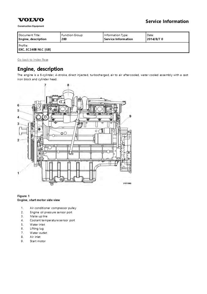
Go back to Index Page Engine, description The
engine is a 6-cylinder, 4-stroke, direct
injected, turbocharged, air to air aftercooled,
water cooled assembly with a cast iron block and
cylinder head.
- Figure 1
- Engine, start motor side view
- Air conditioner compressor pulley
- Engine oil pressure sensor port
- Make up line
- Coolant temperature sensor port
- Water inlet
- Lifting lug
- Water outlet
- Air inlet
- Start motor
2
- Figure 2
- Engine, air heater side view
- Fuel return line
- Air heater
- Coolant preheater port
- Coolant filter supply
- Fuel suction line
- Figure 3
- Engine, top view
- Water inlet
- Return from heater
- Engine oil filler
- Supply to heater
3
- Oil dipstick
- Air inlet
- Water outlet
- Exaust line
- Figure 4
- Engine, front view
- Alternator
- From charge air cooler
- To charge air cooler
- Oil drain valve
4
https//www.ebooklibonline.com Hello dear
friend! Thank you very much for reading. Enter
the link into your browser. The full manual is
available for immediate download. https//www.ebo
oklibonline.com
5
Figure 5 Engine, rear view
6
Service Information
Document Title Engine, description Function Group 200 Information Type Service Information Date 2014/8/7 0
Profile EXC, EC240B NLC GB Profile EXC, EC240B NLC GB Profile EXC, EC240B NLC GB Profile EXC, EC240B NLC GB
Go back to Index Page Engine, description D7E
-Tier 3 / Tier 3 base tier 2 The D7E
configuration is a four stroke, straight six
cylinder, turbocharged, direct injected diesel
engine with charge air cooling and wet,
replaceable cylinder liners. The D7E engine uses
a Common Rail Fuel System controlled by the
engine electronic control (E-ECU)
software. Electronically controlled IEGR
(Internal Exhaust Gas Recirculation) reduces NOx
formation and lowers emissions without the need
for exhaust after treatment (Only applied Tier 3
engine) Volvo's latest engine management system,
EMS 2 is used to control all engine electronic
functions. The cylinders are numbered
consecutively beginning at the flywheel end.
Engine rotational direction is counterclockwise
as seen from the flywheel end.
Figure 1 Engine, D7E
7
Service Information
Document Title Internal Exhaust Gas Recirculation (IEGR), description Function Group 214 Information Type Service Information Date 2014/8/7 0
Profile EXC, EC240B NLC GB Profile EXC, EC240B NLC GB Profile EXC, EC240B NLC GB Profile EXC, EC240B NLC GB
Internal Exhaust Gas Recirculation (IEGR),
description A system for IEGR (Internal Exhaust
Gas Recirculation) is used as part of V-ACT
(Volvo Advanced Combustion Technology). On D6E
and D7E this takes place by an IEGR-opening
piston, controlled by the lubrication oil's
system pressure, acting on the exhaust rocker arm
which enables a second opening of the exhaust
valves. When activated, the secondary piston will
give a limited valve opening of the exhaust
valves during the induction phase, which leads
exhausts back into the cylinder. Included
components IEGR-unit The hydraulic mechanism is
housed in two interconnected IEGR-units, located
on the rocker arm holders. Lubrication oil is
routed from the cylinder head via the solenoid
valve to the high-pressure channel in the
IEGR-unit through a channel in one of the rocker
arm holders.
Figure 1 1. IEGR-unit Solenoid valve The
solenoid valve is located in the cylinder head on
the flywheel side and is activated by the EECU
via the control system EMS 2. When IEGR is not
activated, the solenoid valve is closed and no
oil flow is allowed into the IEGR-unit. At
activation of IEGR, the solenoid valve opens the
channel from the engine's lubrication system to
the IEGR-unit.
8
Figure 2 1. Solenoid valve Control valve The
control valve is located in the IEGR-unit between
the high-pressure circuit and low-pressure
circuit. When the low- pressure circuit is
supplied from the lubrication oil system, the
control valve is lifted and closes the
high-pressure circuit. The ball in the control
valve enables filling of the high-pressure
circuit when IEGR is activated. The lubrication
oil is drained through the control valve.
Figure 3 1. Control valve Main piston The main
piston is acted on by the adjusting screw on the
inlet valve's rocker arm, and affects the oil
pressure in the IEGR- unit's high-pressure
channel. At the end of the IEGR-phase, a pressure
of 100 bar is generated in the high-pressure
circuit.
Figure 4 1. Main piston Servo piston The servo
piston is activated by the hydraulic pressure
from the main piston via a channel in the
IEGR-unit when the IEGR- function is active/on
(solenoid valve in open position). Then the servo
piston opens the exhaust valves via the rocker
arm an extra time during the induction stroke.
9
Figure 5 1. Servo piston Function IEGR is
activated by the system being supplied with full
lubrication oil system pressure via the solenoid
valve. The solenoid valve is activated by the
E-ECU. The control valve closes the high-pressure
circuit and the ball inside the valve enables
filling of the system. With the same movement as
the inlet valve's rocker arm opens the valve, the
main piston is forced upward. The pressure in the
IEGR-unit's high-pressure channel (up to 100 bar)
overcomes the spring force in the servo piston.
the servo piston forces down the rocker arm,
which results in the exhaust valve being open for
a short time at the end of the induction stroke.
Exhausts from the exhaust manifold are sucked
into the cylinder by vacuum from the other
cylinders. The breather hole between the
low-pressure channel and the high-pressure
channel in the IEGR-unit enables longer exhaust
recirculation at high engine speed.
- Figure 6
- IEGR-system (inactive)
- Servo piston
- Control valve
- Solenoid valve
- 25 Bar lubrication oil pressure
- Breather hole
- Oil channel, low-pressure
10
- Oil channel, high-pressure
- Main piston
- Induction rocker arm
- Exhaust rocker arm
- Figure 7
- IEGR-system activated
- Servo piston
- Control valve
- Solenoid valve
- 25 Bar lubrication oil pressure
- Breather hole
- Oil channel, low-pressure
- Oil channel, high-pressure
- Main piston
- Induction rocker arm
- Exhaust rocker arm
- Checking and adjusting
- Checking and adjusting of the IEGR-opening
piston's clearance against the exhaust rocker arm
should be done in connection with checking and
adjusting valves according to 214 Valves,
adjusting. - Software
- The function monitors the EGR valve for return of
combustion gases and informs the operator if the
function is not ensured or if there is a system
malfunction. - The function is also used as input signal for
Engine protection.
11
Service Information
Document Title Valves, adjusting Function Group 214 Information Type Service Information Date 2014/8/7 0
Profile EXC, EC240B NLC GB Profile EXC, EC240B NLC GB Profile EXC, EC240B NLC GB Profile EXC, EC240B NLC GB
Go back to Index Page Valves, adjusting The
valve clearance must be checked and adjusted at
specified intervals. To do this, the engine oil
temperature must be between 20 C (68 F) and 80
C (176 F). Valve clearance adjustment
Item mm inch
Inlet valve 0.3 0.012
Exhaust valve 0.5 0.020
Adjustment
- Figure 1
- Valve clearance, adjustment
- Remove rocker cover.
- Turn crankshaft until both valves in cylinder 1
overlap (Exhaust valve about to close, inlet
valve about to open). - Adjust clearance of valves marked in black in
figure. Mark respective rocker arm with chalk to
show that adjustment has been done.
Figure 2 Lock nut, tightening 4. Tighten down the
lock nut to 20 Nm (15 lbfft) check the
adjustment again with a feeler gauge.
12
- Figure 3
- Valve clearance, adjustment
- Turn crankshaft one full revolution (360). Now
adjust clearance of valves marked black in
figure. - Install the valve cover together with a new
gasket and tighten down the screws. - Tightening torque 9 Nm (6.6 lbfft)
13
Service Information
Document Title Valves, adjusting Function Group 214 Information Type Service Information Date 2014/8/7 0
Profile EXC, EC240B NLC GB Profile EXC, EC240B NLC GB Profile EXC, EC240B NLC GB Profile EXC, EC240B NLC GB
Go back to Index Page Valves, adjusting Op nbr
214-012 9998681 Rotation tool 885812 Timing tool
WARNING
- Risk of burns - stop the diesel engine and allow
it to cool down before starting any work. - Place the machine in service position B. See 091
Service positions - Open the engine hood.
- Remove turbocharger inlet hose (1).
Figure 1 4. Remove dipstick gauge pipe mounting
bracket (1).
Figure 2
14
5. Remove crankcase ventilation duct (1).
Figure 3 6. Remove cable bracket (1).
Figure 4 7. Remove engine intake sensor cover
(1).
Figure 5 8. Disconnect engine intake sensor (1)
and preheating coil terminal (2).
15
Figure 6 9. Remove dust seal (1) and then
remove rocker arm cover (2).
- Figure 7
- Open the side door on the right side of the
machine. - Remove screws and put away two covers.
Figure 8 12. Remove the camshaft gear cover (1)
and install turning gear (2). NOTE! The teeth of
the turning gear must mesh fully with the teeth
of the camshaft gear.
16
Figure 9 13. Remove the IEGR unit. (If
installed) Install M 8 x 75 mm 10.9 screws in
the holes for the IEGR unit on the rocker arm
holders.
Figure 10
14. Setting engine to valve overlap Turn
crankshaft using turning gear (3) until the valve
overlap of cylinder 1 is reached.
- Figure 11
- Wrench
- Extension bar
- Turning gear
- Overlapping means that the exhaust valve is about
to open and the inlet valve is about to close. It
should not be possible to rotate any push rods by
hand for the cylinder in question in this
position.
17
Figure 12 Overlapping
Figure 13 1, 3, 5, 7, 9 and 11 are exhaust
valves 2, 4, 6, 8, 10 are 12 inlet valves 15.
Adjust the valve clearance for each cylinder
according to the black markings in the figure.
Procedure for adjusting
Figure 14
18
- Figure 15
- 885812 Timing tool
- Adjusting screw
- Loosen the adjusting screw's lock bolt on the
rocker arm. - Install the protractor on the adjusting screw.
- Turn the adjusting screw until zero clearance is
obtained between rocker arm and valve. Reset the
protractor to zero. - Turn the adjusting screw counterclockwise 90 for
inlet valve and 150 for exhaust valve. - Hold the adjusting screw and tighten the lock nut
at the same time. Tightening torque see 200
Engine, tightening torques - 16. Rotate the crankshaft another full turn until
the valves for cylinder 6 overlap. Adjust the
valve clearance for each cylinder according to
the black markings in the figure. - NOTE!
- When all valves are adjusted, do not rotate the
engine. Continue directly with installing and
adjusting the IEGR unit.
- Figure 16
- Installing and adjusting IEGR unit (If installed)
- Change the O-rings on the pipe between the two
IEGR sections. Lubricate the O-rings. - Remove the replacement bolts from the IEGR unit's
installation holes.
19
Suggest If the above button click is invalid.
Please download this document first, and then
click the above link to download the complete
manual. Thank you so much for reading
20
- Install the IEGR unit.
- With overlapping valves for cylinder 6, adjust
IEGR-opening piston for cylinder 1, 3 and 5.
Procedure for adjusting IEGR-opening piston
- Figure 17
- 885812 Timing tool
- Adjusting screw
- Loosen the adjusting screw's lock bolt on the
IEGR unit. - Install the protractor on the adjusting screw.
- Turn the adjusting screw until zero clearance is
obtained between the IEGR-opening piston and
exhaust rocker arm. Reset the protractor to zero. - Turn the adjusting screw counterclockwise 144.
- Hold the adjusting screw and tighten the lock nut
at the same time. Tightening torque see 200
Engine, tightening torques - Rotate the crankshaft another full turn until the
valves for cylinder 1 overlap. Adjust
IEGR-opening piston for cylinder 2, 4 and 6. - Install the new gasket on the valve cover.
- NOTE!
- Make sure that the tab (1) on the gasket is
positioned correctly.
21
https//www.ebooklibonline.com Hello dear
friend! Thank you very much for reading. Enter
the link into your browser. The full manual is
available for immediate download. https//www.ebo
oklibonline.com
Recommended
CrystalGraphics Presentations


