

Volvo EW160 Wheeled Excavator Service Repair Manual Instant Download PowerPoint PPT Presentation
Title: Volvo EW160 Wheeled Excavator Service Repair Manual Instant Download
1
Service Information
Document Title Complete engine, removal Function Group 210 Information Type Service Information Date 2014/7/7 0
Profile Profile Profile Profile
Complete engine, removal Op nbr 210-01 Lifting
chains, min. 1000 kg
WARNING
- Before starting any work, allow the diesel engine
to cool down in order to avoid burn injuries. - NOTE!
- In general, all clamps that secure hoses and
electrical cables must be removed. - Turn off the electric power with the battery
disconnector. - Remove the attaching bolts for the gas struts 2
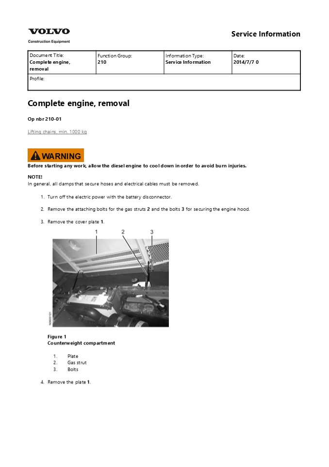
and the bolts 3 for securing the engine hood. - Remove the cover plate 1.
- Figure 1
- Counterweight compartment
- Plate
- Gas strut
- Bolts
- Remove the plate 1.
2
- Figure 2
- Engine compartment
- 1. Plate
- Release the gas strut (hidden) from the engine
hood 2. - Remove the attaching bolts 1 and lift away the
engine hood 2.
- Figure 3
- Engine compartment
- Attaching bolts
- Plate
- 7. Remove the plate 1.
3
- Figure 4
- Hydraulic compartment
- 1. Plate
- Remove the rubber moulding 3 around the frame
parts. - Remove the frame parts1 and 2.
- Figure 5
- Engine compartment
- Frame
- Frame
- Rubber moulding
- 10. Remove the frame part 1.
4
https//www.ebooklibonline.com Hello dear
friend! Thank you very much for reading. Enter
the link into your browser. The full manual is
available for immediate download. https//www.eb
ooklibonline.com
5
- Figure 6
- Engine compartment
- 1. Frame
- Remove the counterweight according to
Counterweight, removalinSection 7 . - Remove the plate 1 underneath the engine.
- Figure 7 Superstructure
- 1. Plate
- Remove the connector 2 from the throttle control.
- Remove the throttle control1 from the engine and
place it to the right by the hydraulic oil tank.
- Figure 8
- Engine compartment
- Throttle control
- Connector
- 15. Remove (if one is fitted) the compressor 1
from the engine, (4 bolts2) and remove the Vee
belts. - NOTE!
- Do not disconnect any hoses from the compressor.
6
- Figure 9
- Engine compartment
- Compressor
- Bolt
- Disconnect the hose 1 from the engine and pinch
the hose with the pliers 2. - Connect a drain hose 3 on the hose connection 1
and drain the engine coolant into a container.
- Figure 10
- Engine compartment
- Hose
- Pliers
- Hose
- Remove the clamp 1 from the member.
- Disconnect the hose 2 from the coolant pump.
7
- Figure 11
- Engine compartment
- Clamp
- Hose
- 20. Pinch the hose 1 and place it according to
Fig. 12.
- Figure 12
- Engine compartment
- 1. Hose
- Remove the ground cables 1 and the cabling 2 to
the starter motor. - Mark up and disconnect the electrical cables from
all sensors and monitors on the engine. - Disconnect the fuel lines ( 2 lines) and plug the
lines and connections.
8
- Figure 13
- Engine compartment
- Ground cables
- Starter motor cabling
- Remove the electrical cables from the alternator
1 . - Remove the hose 2 from the engine and the hose 3
from the crankcase ventilation.
- Figure 14
- Engine compartment
- Alternator
- Hose
- Hose
- 26. Remove the hose 1.
9
- Figure 15
- Hydraulic compartment
- 1. Hose
- Remove the protective plate 1.
- Remove the silencer 2 with bracket and pipe to
the turbo.
- Figure 16
- Engine compartment
- Protective plate
- Silencer
- 29. Remove the attaching bolt 1 from the front
right engine mounting.
10
Figure 17 Engine compartment 1. Attaching
bolts 30. Remove the attaching bolt 1 from the
front left engine mounting.
Figure 18 Engine compartment 1. Attaching
bolts 31. Remove the bolts 1 for the working
pump (1 underneath).
Figure 19
11
Engine compartment 1. Bolts 32. Connect lifting
chains to the lifting eyes 1 on the engine and to
a lifting device.
Figure 20 Engine compartment 1. Lifting
eyes 33. Remove the engine mounting 1 from the
engine.
Figure 21 Engine compartment 1. Engine
mounting 34. Remove the engine mounting 1 from
the engine.
12
Figure 22 Engine compartment 1. Engine
mounting 35. Remove the oil filter 1.
- Figure 23
- Engine compartment
- 1. Oil filter
- Slightly lift the engine and place a block 1
under the connection on the working pump. - Remove the working pump from the engine by moving
the engine backwards. - Lift out the engine.
13
Figure 24 Engine compartment 1. Block 39. Place
the engine on stable supports.
14
Service Information
Document Title Complete engine, installation Function Group 210 Information Type Service Information Date 2014/7/7 0
Profile Profile Profile Profile
- Complete engine, installation
- Op nbr 210-02
- Lifting chains, min. 1000 kg
- NOTE!
- As a general rule, all removed cable ties and
clamps securing hoses and electrical cables must
be replaced. - Transfer the engine mounting 1. Tightening
torque85 Nm - Transfer the alternator2.
- Figure 1 Engine
- Engine mounting
- Alternator
- Transfer the drive flange and the cap 1.
- Transfer the bracket 2.
- Transfer the coolant connection 3.
15
- Figure 2 Engine
- Drive flange/cap
- Bracket
- Connection
- Transfer the engine mounting 1. Tightening
torque 85 Nm - Transfer sensor and monitors that are missing on
the new engine and the crankcase ventilation.
- Figure 3 Engine
- 1. Engine mounting
- Connect lifting chains to the lifting eyes on the
engine and to a lifting device. - Lift the engine into the machine.
16
- Figure 4 Engine
- Fit the working pump to the engine and remove the
block 1. - Lower the engine on the front engine mountings.
Figure 5 Engine compartment 1. Block 12. Fit
the engine mounting 1 on the engine.
Figure 6
17
Engine compartment 1. Engine mounting 13. Fit
the engine mounting 1 on the engine.
Figure 7 Engine compartment 1. Engine
mounting 14. Fit the oil filter 1.
Figure 8 Engine compartment 1. Oil filter 15.
Remove the lifting chains from the lifting eyes 1
on the engine.
18
Figure 9 Engine compartment 1. Lifting eyes 16.
Fit the attaching bolt 1 in the front right
engine mounting. Tightening torque 320 Nm
Figure 10 Engine compartment 1. Attaching
bolts 17. Fit the attaching bolt 1 in the front
left engine mounting. Tightening torque 320 Nm
19
Suggest If the above button click is invalid.
Please download this document first, and then
click the above link to download the complete
manual. Thank you so much for reading
20
Figure 11 Engine compartment 1. Attaching
bolts 18. Fit the bolts 1 for the working pump
(1 underneath). Tightening torque 205 Nm
- Figure 12
- Engine compartment
- 1. Bolts
- Fit the silencer 2 including the pipe to the
turbo. - Fit the protective plate 1.
- Figure 13
- Engine compartment
- Protective plate
- Silencer
- 21. Fit the hose 1 to the turbo.
21
https//www.ebooklibonline.com Hello dear
friend! Thank you very much for reading. Enter
the link into your browser. The full manual is
available for immediate download. https//www.eb
ooklibonline.com
Recommended

