
Toro Reelmaster 5300D Mower Service Repair Manual Instant Download PowerPoint PPT Presentation
Title: Toro Reelmaster 5300D Mower Service Repair Manual Instant Download
1
Reelmaster 5300-D
Part No. 94819SL, Rev. C
Service Manual
Preface
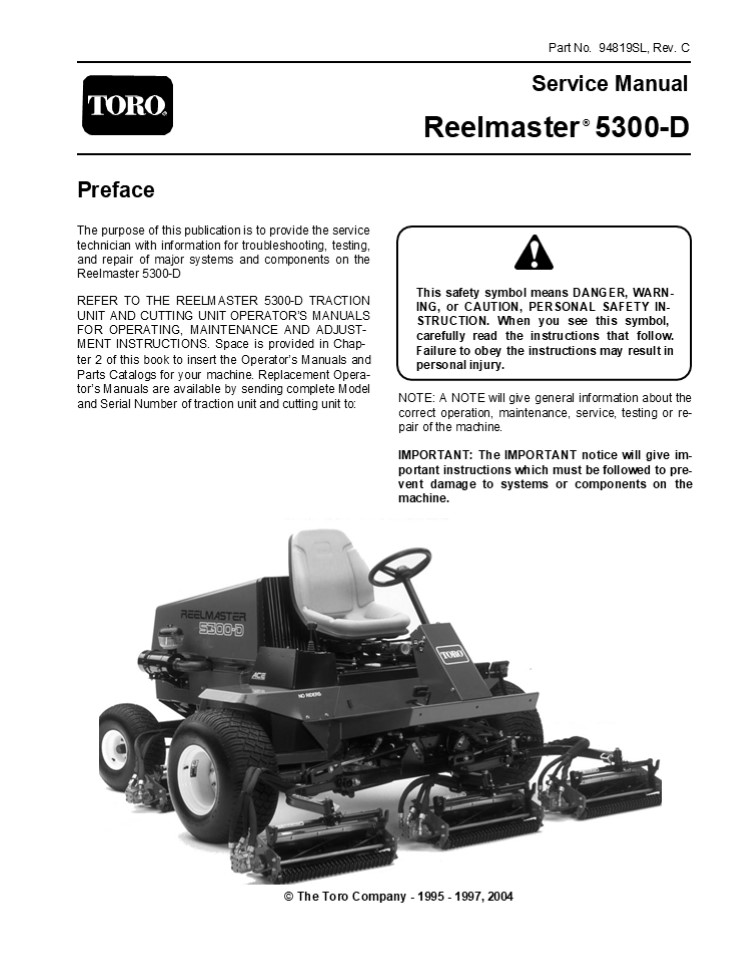
The purpose of this publication is to provide the
service technician with information for
troubleshooting, testing, and repair of major
systems and components on the Reelmaster 5300-D
This safety symbol means DANGER, WARN- ING, or
CAUTION, PERSONAL SAFETY IN- STRUCTION. When you
see this symbol, carefully read the instructions
that follow. Failure to obey the instructions may
result in personal injury.
REFER TO THE REELMASTER 5300-D TRACTION UNIT AND
CUTTING UNIT OPERATORS MANUALS FOR OPERATING,
MAINTENANCE AND ADJUST- MENT INSTRUCTIONS. Space
is provided in Chap- ter 2 of this book to insert
the Operators Manuals and Parts Catalogs for
your machine. Replacement Opera- tors Manuals
are available by sending complete Model and
Serial Number of traction unit and cutting unit
to
NOTE A NOTE will give general information about
the correct operation, maintenance, service,
testing or re- pair of the machine.
IMPORTANT The IMPORTANT notice will give im-
portant instructions which must be followed to
pre- vent damage to systems or components on the
machine.
The Toro Company - 1995 - 1997, 2004
2
Table Of Contents
Chapter 5 - Electrical System
Chapter 1 - Safety
Safety Instructions . . . . . . . . . . . . . . .
. . . . . . . . . 1 - 1
Wiring Schematics and Diagrams. . . . . . . . . .
. . . 5 - 3 Special Tools. . . . . . . . . . . .
. . . . . . . . . . . . . . . . . 5 -
5 Troubleshooting . . . . . . . . . . . . . . . .
. . . . . . . . . . 5 - 7 Testing . . . . . . . .
. . . . . . . . . . . . . . . . . . . . . . . . 5
- 18 Repairs . . . . . . . . . . . . . . . . . .
. . . . . . . . . . . . . . 5 - 28
Chapter 2 - Product Records and Manuals
Product Records . . . . . . . . . . . . . . . . .
. . . . . . . . . 2 - 1 Equivalents and
Conversions . . . . . . . . . . . . . . . . 2 -
2 Torque Specifications . . . . . . . . . . . . .
. . . . . . . . . 2 - 3 Maintenance Interval
Charts. . . . . . . . . . . . . . . . . 2 - 4
Equipment Operation and Service History Report. .
. . . . . . . . . . . . . . 2 - 5
Chapter 6 - Differential Axle
Introduction . . . . . . . . . . . . . . . . . .
. . . . . . . . . . . . 6 - 1 Torque
Specifications . . . . . . . . . . . . . . . . .
. . . . . 6 - 2 Repairs . . . . . . . . . . . . .
. . . . . . . . . . . . . . . . . . . . 6 - 3
Chapter 3 - Mitsubishi S3L2 Diesel Engine
Chapter 7 - Steering and Brakes
Introduction . . . . . . . . . . . . . . . . . .
. . . . . . . . . . . . 3 - 2 Specifications . .
. . . . . . . . . . . . . . . . . . . . . . . . .
. 3 - 3 Special Tools . . . . . . . . . . . . . .
. . . . . . . . . . . . . . 3 - 4 Adjustments . .
. . . . . . . . . . . . . . . . . . . . . . . . .
. . 3 - 6 Repairs . . . . . . . . . . . . . . . .
. . . . . . . . . . . . . . . . . 3 - 7
MITSUBISHI SL-SERIES SERVICE MANUAL
Introduction . . . . . . . . . . . . . . . . . .
. . . . . . . . . . . . 7 - 2 Schematics . . . .
. . . . . . . . . . . . . . . . . . . . . . . . .
. 7 - 3 Specifications . . . . . . . . . . . . .
. . . . . . . . . . . . . . . 7 - 4 Special
Tools. . . . . . . . . . . . . . . . . . . . . .
. . . . . . . 7 - 4 Troubleshooting . . . . . . .
. . . . . . . . . . . . . . . . . . . 7 -
5 Testing . . . . . . . . . . . . . . . . . . . .
. . . . . . . . . . . . . 7 - 7 Adjustments . . .
. . . . . . . . . . . . . . . . . . . . . . . . .
. 7 - 9 Repairs . . . . . . . . . . . . . . . . .
. . . . . . . . . . . . . . . 7 - 11
Chapter 4 - Hydraulic System
Specifications . . . . . . . . . . . . . . . . .
. . . . . . . . . . . 4 - 2 General Information .
. . . . . . . . . . . . . . . . . . . . . . 4 -
3 Hydraulic Schematic. . . . . . . . . . . . . .
. . . . . . . . . 4 - 6 Hydraulic Flow Diagrams .
. . . . . . . . . . . . . . . . . . 4 - 7 Special
Tools . . . . . . . . . . . . . . . . . . . . . .
. . . . . 4 - 12 Troubleshooting . . . . . . . .
. . . . . . . . . . . . . . . . . 4 - 15 Testing
. . . . . . . . . . . . . . . . . . . . . . . . .
. . . . . . . 4 - 25 Adjustments . . . . . . . .
. . . . . . . . . . . . . . . . . . . . 4 -
33 Transmission Repairs . . . . . . . . . . . . .
. . . . . . . . 4 - 35 Mowing Circuit Repairs. .
. . . . . . . . . . . . . . . . . . 4 -
54 Hydraulic Reservoir and Filter . . . . . . . .
. . . . . . 4 - 68
Chapter 8 - Cutting Units
Specifications . . . . . . . . . . . . . . . . .
. . . . . . . . . . . 8 - 2 Special Tools. . . .
. . . . . . . . . . . . . . . . . . . . . . . . .
8 - 3 Troubleshooting . . . . . . . . . . . . . .
. . . . . . . . . . . . 8 - 5 Set-up and
Adjustments . . . . . . . . . . . . . . . . . . .
. 8 - 7 Repairs . . . . . . . . . . . . . . . . .
. . . . . . . . . . . . . . . 8 - 15
Chapter 9 - 4WD Rear Axle
Specifications . . . . . . . . . . . . . . . . .
. . . . . . . . . . . 9 - 2 General Information .
. . . . . . . . . . . . . . . . . . . . . . 9 -
3 Adjustments . . . . . . . . . . . . . . . . . .
. . . . . . . . . . . 9 - 4 Repairs . . . . . . .
. . . . . . . . . . . . . . . . . . . . . . . . .
. 9 - 5
Reelmaster 5300-D
3
Safety
Chapter 1
Safety
Table of Contents
SAFETY INSTRUCTIONS . . . . . . . . . . . . . . .
. . . . . 1 Before Operating . . . . . . . . . .
. . . . . . . . . . . . . . . 1 While Operating .
. . . . . . . . . . . . . . . . . . . . . . . . .
2
While Doing Maintenance, Troubleshooting,
Testing, Adjustments or Repairs . . . . . . . . .
. . . . 3
Safety Instructions
The Reelmaster 5300-D was tested and certified by
TORO for compliance with the B71.4-1990
specifica- tions of the American National
Standards Institutes safety standards for riding
mowers when 65 lbs. of ballast is added to rear
wheels and a rear weight kit, part no. 75-6690 is
installed. Although hazard control and accident
prevention partially are dependent upon the
design and configuration of the machine, these
factors are also dependent upon the awareness,
concern, and proper training of the personnel
involved in the opera- tion, transport,
maintenance, and storage of the machine.
CAUTION I m p roper operat io n, m aint enan ce,
troubleshooting, testing, adjustments or repairs
of the machine can result in injury or death.To
reduce the potential for injury or death, comply
with the following safety in- structions.
4
https//www.ebooklibonline.com Hello dear
friend! Thank you very much for reading. Enter
the link into your browser. The full manual is
available for immediate download. https//www.ebo
oklibonline.com
5
8. Since diesel fuel is highly flammable, handle
it carefully
C. Do not smoke while handling fuel.
D. Fill fuel tank outdoors and only to within an
inch of the top of the tank, not the filler neck.
Do not overfill.
A. Use an approved fuel container.
B. Do not remove fuel tank cap while engine is
hot or running.
E. Wipe up any spilled fuel.
While Operating 9. Sit on the seat when starting
and operating the machine.
G. Avoid sudden stops and starts.
15. Traverse slopes carefully. Do not start or
stop sud- denly when traveling uphill.
10. Before starting the engine
A. Engage the parking brake.
16. Operator must be skilled and trained in how
to drive on hillsides. Failure to use caution on
slopes or hills may cause loss of control and
vehicle to tip or roll possibly resulting in
personal injury or death. On 4 wheel drive
models, always use the seat belt and ROPS
together.
B. Make sure traction pedal is in NEUTRAL and
the ENABLE / DISABLE switch is in DISABLE.
C. After engine is started, release parking brake
and keep foot off traction pedal. Machine must
not move. If movement is evident, the neutral
return mechanism is adjusted incorrectly
therefor, shut engine off and adjust until
machine does not move when traction pedal is
released.
17. If engine stalls or looses headway and cannot
make it to the top of a slope, do not turn
machine around. Always back slowly straight down
the slope.
18. DONT TAKE AN INJURY RISK! When a person or
pet appears unexpectedly in or near the mowing
area, STOP MOWING. Careless operation, combined
with terrain angles, ricochets, or improperly
positioned guards can lead to thrown object
injuries. Do not resume mowing until area is
cleared.
11. Seating capacity is one person. Therefore,
never carry passengers.
12. Do not run engine in a confined area without
ade- quate ventilation. Exhaust fumes are
hazardous and could possibly be deadly.
19. Do not touch engine, muffler or exhaust pipe
while engine is running or soon after is stopped.
These areas could be hot enough to cause burns.
13. Check interlock switches daily for proper
operation. If a switch fails, replace it before
operation the machine. The interlock system is
for your protection, so do not bypass it. Replace
all interlock switches every two years.
20. If cutting unit strikes a solid object or
vibrates abnor- mally, stop immediately, turn
engine off, set parking brake and wait for all
motion to stop. Inspect for damage. If reel or
bedknife is damaged, repair or replace it before
operating. Do not attempt to free blocked cutting
unit by reversing its reel direction. Damage to
the reel may result.
14. Using the machine demands attention. To
prevent loss of control
A. Operate only in daylight or when there is good
artificial light.
21. Before getting off the seat
B. Drive slowly.
A. Move traction pedal to neutral.
C. Watch for holes or other hidden hazards.
B. Set parking brake.
D. Look behind machine before backing up.
C. Disengage cutting units and wait for reels to
stop.
E. Do not drive close to a sand trap, ditch,
creek or other hazard.
D. Stop engine and remove key from switch.
E. Do not park on slopes unless wheels are
chocked or blocked.
F. Reduce speed when making sharp turns and
turning on a hillside.
Safety Instructions
Page 1 - 2
Reelmaster 5300-D
6
While Doing Maintenance, Troubleshooting,
Testing, Adjustments or Repairs
22. Before servicing or making adjustments, stop
the engine and remove the key from the ignition
switch.
32. Disconnect the cables from the battery before
ser- vicing the machine. If battery voltage is
required for troubleshooting or test procedures,
temporarily connect the battery.
23. Make sure machine is in safe operating
condition by keeping all nuts, bolts and screws
tight.
Safety
33. Do not charge a frozen battery because it can
explode and cause injury. Let the battery warm to
60o F (15.5o C) before connecting to a charger.
Charge the battery in a well-ventilated place so
that gases produced while charging can dissipate.
Since the gases are ex- plosive, keep open flame
and electrical spark away from the battery do
not smoke. Nausea may result if the gases are
inhaled. Unplug the charger from the electri- cal
outlet before connecting or disconnecting the
charger leads from the battery posts.
24. Frequently inspect all hydraulic line
connectors and fittings. Make sure all hydraulic
hoses and lines are in good condition before
applying pressure to the system.
25. Keep body and hands away from pin hole leaks
or nozzles that eject high pressure hydraulic
fluid. Use cardboard or paper to find hydraulic
leaks. Hydraulic fluid escaping under pressure
can penetrate the skin and cause injury. Fluid
accidentally injected into the skin must be
surgically removed within a few hours by a doctor
or gangrene may occur.
34. Wear safety glasses, goggles or a face shield
to prevent possible eye injury when using
compressed air for cleaning or drying components.
26. Before disconnecting, or performing any work
on the hydraulic system, lower the cutting units
to the ground and stop the engine so all pressure
is relieved.
35. Failure to follow proper procedures when
mounting a tire on a wheel or rim can produce an
explosion which may result in serious injury. Do
not attempt to mount a tire unless you have the
proper equipment and ex- perience to perform the
job. Have it done by your Toro Distributor or a
qualified tire service.
27. Be sure you understand a service procedure
before working on the machine. Unauthorized
modifications to the machine may impair the
function, safety and life of the machine. If
major repairs are ever needed, or assis- tance is
desired, contact your TORO Distributor.
36. When changing attachments or performing other
service, use the correct blocks and hoists.
Always use jackstands to safely support the
machine when it is raised by a jack or hoist.
28. To reduce potential fire hazard, keep engine
area free of excessive grease, grass, leaves and
dirt. Clean protective screen on front of engine
frequently. Do not use flammable solvents for
cleaning parts. Do not use diesel fuel, kerosene
or gasoline.
37. Do not use your hand to prevent cutting unit
reel from turning while servicing this can
result in personal injury. Use a 1-1/2 in. thick
x 4 in. wide x 8 in. long piece of hardwood
inserted into front of cutting unit between reel
blades.
29. If the engine must be running to perform an
inspec- tion or procedure, use extreme caution.
Always use two people, with the operator at the
controls able to see the person doing the
inspection or procedure. Keep hands, feet,
clothing, and body away from cutting units and
other moving parts.
38. For optimum performance and safety, use
genuine Toro replacement parts and accessories.
Replacement parts and accessories made by other
manufacturers may result in non-conformance with
the safety stand- ards, and the warranty may be
voided.
30. Do not overspeed the engine by changing
governor setting.
31. Shut engine off before checking or adding oil
to the engine crankcase.
Reelmaster 5300-D
Page 1 - 3
Safety Instructions
7
Product Records and Manuals
Chapter 2
Table of Contents
PRODUCT RECORDS . . . . . . . . . . . . . . . . .
. . . . . . 1 EQUIVALENTS AND CONVERSIONS . . . .
. . . . . . 2 Decimal and Millimeter Equivalents
. . . . . . . . . . 2 U.S. to Metric Conversions
. . . . . . . . . . . . . . . . . 2
TORQUE SPECIFICATIONS . . . . . . . . . . . . . .
. . . . 3 Capscrew Markings and Torque Values -
U.S. . . 3 Capscrew Markings and Torque Values -
Metric . 3 MAINTENANCE INTERVAL CHART . . . . . .
. . . . . . 4 OPERATON AND SERVICE HISTORY REPORT
Product Records and Manuals
Product Records
Record information about your Reelmaster 5300-D
on the OPERATION AND SERVICE HISTORY REPORT form.
Use this information when referring to
your machine.
Insert Operators Manuals and Parts Manuals for
your Reelmaster 5300-D at the end of this section.
Reelmaster 5300-D
Page 2 - 1
Product Records
8
Equivalents and Conversions
Decimal and Millimeter Equivalents
Fractions Decimals mm Fractions Decimals mm
1/64 0.015625 0.397 33/64 0.515625 13.097
1/32 0.03125 0.794 17/32 0.53125 13.494
3/64 0.046875 1.191 35/64 0.546875 13.891
1/16 0.0625 1.588 9/16 0.5625 14.288
5/64 0.078125 1.984 37/64 0.578125 14.684
3/32 0.9375 2.381 19/32 0.59375 15.081
7/64 0.109275 2.778 39/64 0.609375 15.478
1/8 0.1250 3.175 5/8 0.6250 15.875
9/64 0.140625 3.572 41/64 0.640625 16.272
5/32 0.15625 3.969 21/32 0.65625 16.669
11/64 0.171875 4.366 43/64 0.671875 17.066
3/16 0.1875 4.762 11/16 0.6875 17.462
13/64 0.203125 5.159 45/64 0.703125 17.859
7/32 0.21875 5.556 23/32 0.71875 18.256
15/64 0.234375 5.953 47/64 0.734375 18.653
1/4 0.2500 6.350 3/4 0.7500 19.050
17/64 0.265625 6.747 49/64 0.765625 19.447
9/32 0.28125 7.144 25/32 0.78125 19.844
19/64 0.296875 7.541 51/64 0.796875 20.241
5/16 0.3125 7.938 13/16 0.8125 20.638
21/64 0.328125 8.334 53/64 0.828125 21.034
11/32 0.34375 8.731 27/32 0.84375 21.431
23/64 0.359375 9.128 55/64 0.859375 21.828
3/8 0.3750 9.525 7/8 0.8750 22.225
25/64 0.390625 9.922 57/64 0.890625 22.622
13/32 0.40625 10.319 29/32 0.90625 23.019
27/64 0.421875 10.716 59/64 0.921875 23.416
7/16 0.4375 11.112 15/16 0.9375 23.812
29/64 0.453125 11.509 61/64 0.953125 24.209
15/32 0.46875 11.906 31/32 0.96875 24.606
31/64 0.484375 12.303 63/64 0.984375 25.003
1/2 0.5000 12.700 1 1.000 25.400
1 mm 0.03937 in. 1 mm 0.03937 in. 0.001 in. 0.0254 mm 0.001 in. 0.0254 mm
U.S to Metric Conversions
To Convert Into Multiply By
Linear Miles Kilometers 1.609
Measurement Yards Meters 0.9144
Feet Meters 0.3048
Feet Centimeters 30.48
Inches Meters 0.0254
Inches Centimeters 2.54
Inches Millimeters 25.4
Area Square Miles Square Kilometers 2.59
Square Feet Square Meters 0.0929
Square Inches Square Centimeters 6.452
Acre Hectare 0.4047
Volume Cubic Yards Cubic Meters 0.7646
Cubic Feet Cubic Meters 0.02832
Cubic Inches Cubic Centimeters 16.39
Weight Tons (Short) Metric Tons 0.9078
Pounds Kilograms 0.4536
Ounces (Avdp.) Grams 28.3495
Pressure Pounds/Sq. In. Kilopascal 6.895
Pounds/Sq. In. Bar 0.069
Work Foot-pounds Newton-Meters 1.356
Foot-pounds Kilogram-Meters 0.1383
Inch-pounds Kilogram-Centimeters 1.152144
Liquid Volume Quarts Liters 0.9463
Gallons Liters 3.785
Liquid Flow Gallons/Minute Liters/Minute 3.785
Temperature Fahrenheit Celsius 1. Subract 32o
2. Multiply by 5/9
Equivalents and Conversions
Page 2 - 2
Reelmaster 5300-D
9
Torque Specifications
Use these torque values when specific torque
values are not given. DO NOT use these values in
place of
specified values. Torque values listed are for
lubricated threads. Plated threads are considered
to be lubricated.
Capscrew Markings and Torque Values - U.S.
Customary
SAE Grade Number 5 5 5 5 8 8 8 8
Capscrew Head Markings
Capscrew Body Size ft-lb Capscrew Torque - Grade 5 Cast Iron Aluminum Nm ft-lb Nm Capscrew Torque - Grade 5 Cast Iron Aluminum Nm ft-lb Nm Capscrew Torque - Grade 5 Cast Iron Aluminum Nm ft-lb Nm ft-lb Capscrew Torque - Grade 8 Cast Iron Aluminum Nm ft-lb Nm Capscrew Torque - Grade 8 Cast Iron Aluminum Nm ft-lb Nm Capscrew Torque - Grade 8 Cast Iron Aluminum Nm ft-lb Nm
1/4-20 7 9 6 8 11 15 9 12
-28 9 12 7 9 13 18 10 14
5/16-18 15 20 12 16 22 30 18 24
-24 17 23 14 19 24 33 19 25
3/8-16 30 40 20 25 40 55 30 40
-24 30 40 25 35 45 60 35 45
7/16-14 45 60 35 45 65 90 50 65
-20 50 65 40 55 70 95 55 75
1/2-13 70 95 55 75 95 130 75 100
-20 75 100 60 80 110 150 90 120
9/16-12 100 135 80 110 140 190 110 150
-18 110 150 85 115 155 210 125 170
5/8-11 135 180 110 150 190 255 150 205
-18 155 210 120 160 215 290 170 230
3/4-10 240 325 190 255 340 460 270 365
-16 270 365 210 285 380 515 300 410
7/8-9 360 490 280 380 550 745 440 600
-14 390 530 310 420 610 825 490 660
1-8 530 720 420 570 820 1100 660 890
-14 590 800 480 650 890 1200 710 960
Product Records and Manuals
Capscrew Markings and Torque Values Metric
Commercial Steel Class Commercial Steel Class 8.8 8.8 10.9 10.9 10.9 10.9 12.9 12.9 12.9 12.9
Capscrew Head Markings Capscrew Head Markings Capscrew Head Markings Capscrew Head Markings Capscrew Head Markings
Thread Diameter mm Capscrew Torque - Class 8.8 Cast Iron Aluminum ft-lb Nm ft-lb Nm Capscrew Torque - Class 8.8 Cast Iron Aluminum ft-lb Nm ft-lb Nm Capscrew Torque - Class 8.8 Cast Iron Aluminum ft-lb Nm ft-lb Nm Capscrew Torque - Class 8.8 Cast Iron Aluminum ft-lb Nm ft-lb Nm Capscrew Torque - Class 10.9 Cast Iron Aluminum ft-lb Nm ft-lb Nm Capscrew Torque - Class 10.9 Cast Iron Aluminum ft-lb Nm ft-lb Nm Capscrew Torque - Class 10.9 Cast Iron Aluminum ft-lb Nm ft-lb Nm Capscrew Torque - Class 10.9 Cast Iron Aluminum ft-lb Nm ft-lb Nm Capscrew Torque - Class 12.9 Cast Iron Aluminum ft-lb Nm ft-lb Nm Capscrew Torque - Class 12.9 Cast Iron Aluminum ft-lb Nm ft-lb Nm Capscrew Torque - Class 12.9 Cast Iron Aluminum ft-lb Nm ft-lb Nm Capscrew Torque - Class 12.9 Cast Iron Aluminum ft-lb Nm ft-lb Nm
6 5 9 4 7 9 14 7 11 9 14 7 11
7 9 14 7 11 14 18 11 14 18 23 14 18
8 18 25 14 18 23 32 18 25 27 36 21 28
10 30 40 25 30 45 60 35 45 50 70 40 55
12 55 70 40 55 75 105 60 80 95 125 75 100
14 85 115 65 90 120 160 95 125 145 195 110 150
16 130 180 100 140 175 240 135 190 210 290 165 220
18 170 230 135 180 240 320 185 250 290 400 230 310
Reelmaster 5300-D
Page 2 - 3
Torque Specifications
10
Maintenance Interval Chart
Maintenance Interval Chart
Page 2 - 4
Reelmaster 5300-D
11
REELMASTER 223-D, 5100-D, and 5300-D Maintenance
Schedule Minimum Recommended Maintenance
Intervals
Maintenance Procedure Maintenance Interval Service
Every Every 400hrs 800hrs Service Air Filter Replace Electric Fuel Pump Filter Replace Fuel/WaterSeparator Filter Inspect Traction Linkage Movement Torque Head and Adjust Valves D Check Engine RPM (idle and full throttle) Level Change Hydraulic Fluid Change Transmission Fluid Replace Transmission Filter Check Rear Wheel Toe-in Rear Axle Service pack Rear Wheel Bearings (2WD) E Level change Rear Axle Lubricant (4WD) Service
Initial break in at 10 hours Initial break in at 50 hours
Replace Moving Hoses Replace Safety Switches Annual Recommendations Items listed are recommended every 1600 Coolant System - Flush/Replace Fluid hours or 2 years whichever occurs first. Fuel Tank - Drain/Flush Hydraulic Tank - Drain/Flush
Check Battery Fluid Level Every Every 100hrs Check Battery Cable Connections 50hrs Lubricate All Grease Fittings Change Engine Oil A Level Inspect Air Filter, Dust Cup, and Baffle Service Check Fan and Altenator Belt Tension Replace Engine Oil Filter B Level Inspect Cooling System Hoses Service Every 200hrs
Drain Moisture-Hyd. Tank Drain Moisture-Fuel Tank Check Reel Bearing Preload Adjustment C Torque Wheel Lug Nuts Level Drain Moisture-Hyd. Tank Drain Moisture-Fuel Tank Check Reel Bearing Preload Adjustment C Torque Wheel Lug Nuts Level
(See Operator's and Service Manual for
specifications and procedures)
12
REELMASTER 223-D, 5100-D and 5300-D Daily
Maintenance Check List
Unit Designation TORO ID -
Daily Maintenance(duplicate this page for
routine use)
Daily Maintenance Check For Week Of Daily Maintenance Check For Week Of Daily Maintenance Check For Week Of Daily Maintenance Check For Week Of Daily Maintenance Check For Week Of Daily Maintenance Check For Week Of Daily Maintenance Check For Week Of
Maintenance Check Item MON HRS TUES HRS WED HRS THURS HRS FRI HRS SAT HRS SUN HRS
Safety Interlock Operation MON HRS TUES HRS WED HRS THURS HRS FRI HRS SAT HRS SUN HRS
Brake Operation MON HRS TUES HRS WED HRS THURS HRS FRI HRS SAT HRS SUN HRS
Engine Oil Fuel Level MON HRS TUES HRS WED HRS THURS HRS FRI HRS SAT HRS SUN HRS
Cooling System Fluid Level MON HRS TUES HRS WED HRS THURS HRS FRI HRS SAT HRS SUN HRS
Drain Water/Fuel Separator
Air Filter/Pre-Cleaner Condition
Radiator Screen for Debris
Unusual Engine Noises1
Unusual Operating Noises
Transmission Oil Level
Hydraulic System Oil Level
Hydraulic Filter Indicator2
Hydraulic Hoses for Damage
Fluid Leaks
Tire Pressure
Instrument Operation
Reel-to-Bedknife Adjustment
Height-of-Cut Adjustment
Cutting Units Shear Pin
Lubricate All Grease Fittings3
Touch-up damaged paint
1 Check glow plugs and injector nozzles, if
hard starting, excess smoke, or rough running is
noted. 2 Check with engine running and oil at
operating temperature. 3 Immediately after
every washing, regardless of the interval
listed. Notation for areas of concern Inspection
performed by
Item Date Information
1
2
3
4
5
6
7
(See Operator's and Service Manual for
specifications and procedures)
13
C -Service (every 200 hours) Drain Moisture-Hyd.
Tank Drain Moisture-Fuel Tank Check Reel Bearing
Preload Torque Wheel Lug Nuts A and B Service
required
Other - Annual Service and Specials Replace
Moving Hoses Replace Safety Switches Coolant
System - Flush/Replace Fluid Fuel Tank -
Drain/Flush Hydraulic Tank - Drain/Flush
Date
Remarks
Form No. 95-839-SL
REELMASTER 223-D, 5100-D, and 5300-D Supervisor
Maintenance Work Order
E -Service (every 800 hours) Change Hydraulic
Fluid Change Transmission Fluid Replace
Transmission Filter Check Rear Wheel Toe-in Pack
Rear Wheel Brgs/Change 4WD Oil A, B, C, and D
Service required
B -Service (every 100 hours) Check Fan and
Altenator Belt Tension Replace Engine Oil Filter
Inspect Cooling System Hoses A-Service required
(See Operator's and Service Manual for
specifications and procedures)
TORO I.D. - Service to perform (circle)
Other
A -Service (every 50 hours) Check Battery Fluid
Level Check Battery Cable Connections Lubricate
All Grease Fittings Change Engine Oil Inspect Air
Filter, Dust Cup, and Baffle
D -Service (every 400 hours) Service Air
Filter Replace Electric Fuel Pump Filter Replace
Fuel/WaterSeparator Filter Inspect Traction
Linkage Movement Torque Head and Adjust
Valves Check Engine RPM (idle and full
throttle) A, B, and C Service required
E
(duplicate this page for routine use)
D
C
B
A
Unit Designation
Technician
Hours
14
Engine
Chapter 3
Table of Contents
INTRODUCTION . . . . . . . . . . . . . . . . . .
. . . . . . . . . 2 SPECIFICATIONS . . . . . . .
. . . . . . . . . . . . . . . . . . . 3 SPECIAL
TOOLS . . . . . . . . . . . . . . . . . . . . . .
. . . . . 4 ADJUSTMENTS . . . . . . . . . . . . .
. . . . . . . . . . . . . . . 6 Engine Speed
Adjustments . . . . . . . . . . . . . . . . .
6 Throttle Linkage Adjustment . . . . . . . . . .
. . . . . . 6
REPAIRS . . . . . . . . . . . . . . . . . . . . .
. . . . . . . . . . . . 7 Cooling Fan Belt
and Alternator Belt Replacement . . . . . . . . .
. . . . . . . 7 Bleeding the Fuel System . . . .
. . . . . . . . . . . . . . 8 Bleeding Air From
the Injectors . . . . . . . . . . . . . . 9
Removing and Installing the Fuel Tank . . . . . .
. 10 Replacing and/or Adjusting Engine Stop (ETR)
Solenoid . . . . . . . . . . . . . . .
11 Removing the Engine . . . . . . . . . . . . .
. . . . . . . 12 Installing the Engine . . . . .
. . . . . . . . . . . . . . . . 13
Engine
Reelmaster 5300-D
Page 3 - 1
Table of Contents
15
Introduction
This chapter gives information about
specifications, maintenance, troubleshooting,
testing and repair of the diesel engine used in
the Reelmaster 5300-D mower.
The engine used in the Reelmaster 5300-D mower
is manufactured by Mitsubishi Heavy Industries
Limited. Service and repair parts for Mitsubishi
engines are supplied through TORO Distributors.
Repair parts may be ordered by TORO Part Number.
If no parts list is available be sure to provide
your dealer or distributor with the TORO Model
Number and Serial Number.
Most repairs and adjustments require tools which
are commonly available in many service shops.
Special tools are described in the Special Tools
section. The use of some specialized test
equipment is explained, how- ever, the cost of
the test equipment and the specialized nature of
some repairs may dictate that the work be done at
a qualified diesel engine repair facility.
Introduction
Page 3 - 2
Reelmaster 5300-D
16
Specifications
Item Specification
Make/Designation Mitsubishi S3L2, 4 cycle, liquid cooled, vertical overhead valve diesel
Combustion Chamber Swirl chamber type
Number of Cylinders 3
Bore x Stroke 78 x 92 mm
Total Displacement 1.318 Liter
Compression Ratio 31
Firing Order 1 - 3 - 2
Dry Weight (approximate) 125 kg (276 lb.)
Fuel Diesel
Fuel Injection Pump Bosch type ND-PFR-NC
Governor Mechanical centrifugal weight type
Fuel Injector Nozzle Nippon Denso throttle type
Fuel Injection Pressure (140 kg/cm2) 1990 psi
Lubrication System Forced lubrication
Oil Pump Gear type
Oil Filter Paper element filter (full flow type)
Crankcase Oil Capacity including filter of 0.5 liter (0.6 qt.) capacity 4.1 Liter (3.9 qt.)
Cooling System Forced circulation, water cooling
Water Pump Centrifugal type
Cooling System Capacity Total System (approximate) 10.1 Lliter (9.6 qt.)
Starter Solenoid shift type 1.6 kW (12 volt)
Alternator AC type 12 volt 50A
Glow Plug Quick heat sheathed type
Engine
Reelmaster 5300-D
Page 3 - 3
Specifications
17
Special Tools
Order special tools from TORO SPECIAL TOOLS AND
APPLICATIONS GUIDE (Commercial Products). Some
tools may be available from a local supplier.
Filter Cleaner Filter cleaner (Fig. 1). Mix with
water and use solution to wash the Donaldson air
cleaner element.
Figure 1
Diesel Engine Compression Test Kit Diesel engine
compression test kit (Fig. 2). 0-1000 PSI Gauge
allows testing of diesel engines to check general
operating condition of engine. Includes case,
gauge with hose, glow plug hole adapters and
instructions.
Figure 2
Piston Pin Tool Piston pin tool (Fig. 3) is used
to remove and install the wrist pin without
distorting the piston. Includes an adapt- er for
use with Mitsubishi and most other engines.
Figure 3
Special Tools
Page 3 - 4
Reelmaster 5300-D
18
Nozzle Tester Nozzle tester (Fig. 4). Tests
condition and opening pressure of fuel injector
nozzles.
Figure 4
Nozzle Tester Adapter Nozzle tester adapter
(Fig.5) is required to test the fuel injection
nozzles.
Engine
Figure 5
Reelmaster 5300-D
Page 3 - 5
Special Tools
19
Adjustments
Engine Speed Adjustments Adjustments to the
engine speed settings are not nor- mally
necessary unless the throttle linkage, injection
pump, or governor mechanism have been repaired,
rebuilt, replaced or are not operating
correctly. The high speed set bolt has been set
properly and sealed at the factory. Never tamper
with the seal unless necessary. Idle Speed (no
load) 1700 50 0 rpm Maximum engine speed (no
load) 3200 50 rpm 0 See Engine Service
Manual for Engine Speed Adjust- ment procedure.
- Throttle Linkage Adjustment
- Push the throttle lever forward until it stops
against the slot in the seat base (Fig. 6). - Loosen the throttle cable connector on the lever
arm at the injection pump (Fig. 7). - Hold the injection pump lever arm against the
high idle stop and tighten the cable connector.
NOTE When tightened, the cable connector must be
free to swivel.
2
1
4. Make sure the throttle cable conduit does not
interfere with the full range of motion of the
throttle lever or governor lever.
Figure 6
5. Tighten locknut on throttle lever pivot to 40
- 55 in-lb (Fig. 6). The maximum force required
to operate the throttle lever should be 20 lb.
1. Throttle lever
2. Locknut
1
Figure 7 1. Injection pump lever arm
Adjustments
Page 3 - 6
Reelmaster 5300-D
20
Repairs
Fan Belt and Alternator Belt Replacement 1. Put
machine on a level surface, engage parking brake,
stop engine and remove key from ignition switch.
Open hood.
1
2. Loosen locknut on belt tensioner lever (Fig.
8). If replacing alternator belt, loosen bolt
securing alternator brace to engine and bolt
securing alternator to brace (Fig. 9).
2
3. Remove three capscrews securing transmission
drive shaft coupler to engine crankshaft pulley
(Fig. 10). Do not disconnect drive shaft from
transmission.
4. Move drive shaft out of the way so the belt(s)
can be removed.
Figure 8
5. Install new belt(s).
Engine
1. Fan belt
2. Tensioner lever
6. Connect drive shaft coupler to engine
crankshaft pulley with two capscrews and
lockwashers.
1
7. Adjust belt tension Alternator belt Insert
pry bar between alternator and engine and
carefully pry alternator out until proper tension
is achieved. Belt should deflect 3/8 to 1/2 in.
when 22 lb. of force is applied to belt midway
between crankshaft pulley and alternator pulley.
Tighten alternator and brace bolts to secure
adjust- ment.
Cooling fan belt Apply 5 - 10 lb. of force at
end of lever. Tighten lock nut to secure
adjustment.
Figure 9
1. Alternator belt
30 - 35 ft-lb 2 1
Figure 10
1. Drive shaft coupling
2. Capscrew lockwasher (3)
Reelmaster 5300-D
Page 3 - 7
Rev. B
Repairs
21
- Bleeding the Fuel System
- Stop the engine and engage the parking brake.
Open the hood. - Loosen the air bleed screw on the fuel filter /
water separator (Fig. 11). - Turn the ignition key switch to the ON position.
The electric fuel pump will begin to operate and
force fuel out around the screw loosened in step
2. Fuel will fill the filter bowl and then flow
out around the screw. When a solid stream of fuel
flows out around the screw, tighten the screw and
turn the key switch OFF.
4. Open the air vent screw on the fuel injection
pump (Fig. 12).
Figure 11
5. Turn the ignition key switch to the ON
position. The electric fuel pump will begin to
operate and force fuel out around the injection
pump air vent screw. When a solid stream of fuel
flows out around the screw, tighten the screw and
turn the key switch OFF.
1. Bleed screw
NOTE Normally the engine should start after this
pro- cedure. If the engine does not start, air
may be trapped between the injection pump and
injectors (See Bleeding Air From the Injectors).
1
Figure 12 1. Fuel injection pump air vent screw
Repairs
Page 3 - 8
Reelmaster 5300-D
22
Bleeding Air From the Injectors This procedure
should only be used if the fuel system has been
purged of air. (See Bleeding the Fuel System in
this section of the book.)
1. Loosen the pipe connection at the number one
nozzle and holder assembly on the cylinder head
(Fig. 13).
1
- Move the throttle control to the FAST position.
- Turn the ignition key to the START position to
crank the engine and pump fuel to the nozzles.
Turn the ignition key to the OFF position when a
steady stream of fuel flows out of the loose pipe
connection.
4. Tighten the pipe connector.
Figure 13
5. Repeat steps 1 - 4 for the No. 2 and No. 3
injector nozzle and holder.
1. Fuel injector nozzle and holder (3)
Engine
Reelmaster 5300-D
Page 3 - 9
Repairs
23
Removing and Installing the Fuel Tank 1. Put
machine on a level surface, lower the cutting
units, stop the engine, engage the parking brakes
and remove the key from the ignition switch.
2. Open drain fitting on bottom of fuel tank and
drain fuel into a suitable container (Fig. 14).
1
- Remove six capscrews securing the fender to the
frame and remove the fender. - Disconnect fuel lines from fittings on top of
fuel tank. - Disconnect electrical wire from fuel gauge sender.
6. Remove three capscrews, flat washers and lock-
washers securing fuel tank to frame and remove
fuel tank.
Figure 14
1. Fuel tank drain fitting
7. Reverse steps 2 - 6 to install the fuel tank
and tank base. When installing the tank to the
frame, tighten the screws to a torque of 30 - 60
in-lb (Fig. 15). Do not overtighten.
30 - 60 in-lb
Figure 15
Repairs
Page 3 - 10
Reelmaster 5300-D
24
Replacing and/or Adjusting Engine Stop (ETR)
Solenoid See Chapter 5 - Electrical System for
information about testing the engine stop
solenoid.
An improperly adjusted stop solenoid can result
in failure of the engine to stop when the key
switch is turned off or could cause injection
pump damage or malfunction.
1
Removing the Stop Solenoid
1. Stop the engine. If the engine will not stop
when the ignition key switch is turned off,
manually push the stop lever toward the rear of
the machine until the engine stops.
2
Figure 16
2. Disconnect the solenoid electrical connector.
- Fuel stop (ETR) solenoid
- Governor tie rod cover
3. Loosen the nut securing the solenoid to the
engine and unscrew the solenoid.
Engine
4. If you will be installing a new solenoid,
remove the gasket and nut from the old solenoid
and install them on the new solenoid. Thread the
nut completely on the new solenoid.
2
Installing and/or Adjusting the Stop Solenoid
1
- Remove the governor tie rod cover (Fig. 16).
- Apply thread sealant to the solenoid threads.
- Thread the solenoid into the engine.
Figure 17
4. Thread the solenoid into the engine while
moving the tie rod back and forth (Fig. 17). Stop
screwing the solenoid into the engine when there
is no free play in the tie rod.
- Solenoid plunger
- Tie rod
- Turn the solenoid outward (counterclockwise) 1/4
to 1/2 turn. There should be a small amount of
free play in the injector pump control rack 0.01
- 0.03 in. (0.3 - 0.7 mm). - IMPORTANT No free play in the control rack with
the solenoid de-energized (plunger out) may cause
injection pump damage or malfuntion. Excess free
play 0.04 in. (1 mm) or more will prevent the
engine from stopping when the solenoid is
de-energized. - Hold the solenoid body to prevent it from turning
and tighten the nut against the engine to secure
the adjust- ment. Do not over tighten the nut. If
the nut is over tightened, the solenoid may
become distorted and will not operate correctly. - Connect the solenoid electrical connector.
8. Install the governor tie rod cover.
Reelmaster 5300-D
Page 3 - 11
Repairs
25
Suggest For more complete manuals. Please go to
the home page. https//www.ebooklibonline.com If
the above button click is invalid. Please
download this document first, and then click the
above link to download the complete manual. Thank
you so much for reading
26
Removing and Installing the Engine
Removing the Engine
Figure 18
1. Put machine on a level surface, lower the
cutting units, stop the engine, engage the
parking brakes and remove key from ignition
switch. Allow engine and radiator to cool.
CAUTION DO NOT open radiator cap or drain coolant
if engine or radiator is hot. Pressurized, hot
coolant can escape and cause burns.
2. Open hood. Disconnect hood stop cable from
frame. Lower hood. Remove left and right hinge
plates. Lift hood off chassis.
Ethylene-glycol antifreeze is poisonous. Dis-
pose of it properly or store in a properly
labeled container away from children or pets.
3. Disconnect positive () and negative ()
battery cables from battery. Loosen battery
securing bolt and remove battery.
6. Loosen hose clamps and disconnect upper and
lower radiator hoses from engine and radiator.
Lift coolant expansion tank off of bracket.
4. Remove rear lift arm down pressure springs
(see Chapter 8 - Cutting Units).
5. Open radiator cap. Put a drain pan under left
side of radiator. Open radiator drain valve and
allow coolant to drain into drain pan.
7. Remove plug from right side cylinder block to
drain coolant from engine.
8. Loosen hose clamps and disconnect air intake
hose from engine and air cleaner.
Removing and Installing the Engine
Page 3 - 12
Reelmaster 5300-D
27
9. Remove muffler. Keep muffler bracket on engine.
13. Remove four (4) capscrews, washers and
locknuts to remove fan shroud from radiator.
10. Loosen hose clamp and remove fuel hose from
injector pump. Plug end of fuel line to prevent
fuel leakage. Loosen hose clamp and remove fuel
return hose from rear fuel injector on engine.
14. Loosen cap screw and nut to disconnect
throttle cable from governor lever on engine.
Loosen clamp and remove throttle cable and from
fan bracket.
11. Disconnect and tag wires that attach to
engine or engine components
15. Remove locknut, flat washer, bolt and rebound
washer securing engine to each of four (4) rubber
engine mounts.
Alternator Starter motor and solenoid Ground
cables Oil pressure switch Temperature gauge
sender Thermoswitch Engine stop solenoid Glow
indicator
16. Attach a short section of chain between
lifting holes in fan bracket and muffler bracket.
Connect hoist or block and tackle chain at center
of short section of chain. One person should
operate hoist or block and tackle and the other
person should help guide engine out of chas- sis.
Remove engine from chassis. Be careful when
removing engine to prevent damage to engine,
radiator, fan or other parts. Mount engine in an
engine rebuilding stand.
12. Remove two (2) capscrews and lockwashers to
disconnect drive shaft coupler from engine
crankshaft pulley.
17. Remove fan, brackets and accessories from
engine as necessary. Drain oil from engine and
remove engine oil filter.
Engine
Installing the Engine Installing the Engine Installing the Engine
1. To install the engine, perform steps 2 - 17 of Remov- of ethylene glycol antifreeze and clean, soft water.
ing the Engine in reverse order. Check for oil and coolant leaks and repair as necessary. Check for oil and coolant leaks and repair as necessary.
2. Install a new engine oil filter. Fill engine with the 3. Adjust throttle linkage (See Throttle Linkage Adjust- 3. Adjust throttle linkage (See Throttle Linkage Adjust-
correct oil. Fill the cooling system with a 50/50 solution ment in the Adjustments section of this chapter). ment in the Adjustments section of this chapter).
Reelmaster 5300-D
Page 3 - 13
Removing and Installing the Engine
28
https//www.ebooklibonline.com Hello dear
friend! Thank you very much for reading. Enter
the link into your browser. The full manual is
available for immediate download. https//www.ebo
oklibonline.com
Recommended
