
John Deere 430 Combines Service Repair Manual Instant Download (tm4222)
Title:
John Deere 430 Combines Service Repair Manual Instant Download (tm4222)
Description:
John Deere 430 Combines Service Repair Manual Instant Download (tm4222) –
Number of Views:0
Title: John Deere 430 Combines Service Repair Manual Instant Download (tm4222)
1
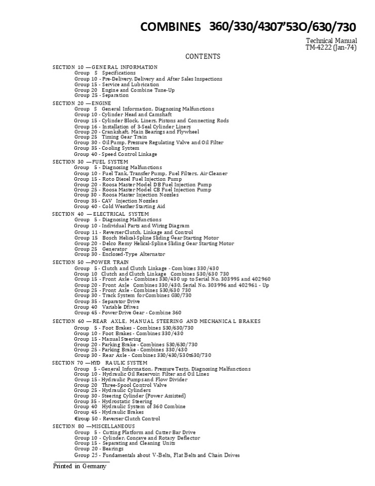
COMBINES 360/330/430753O/630/730
Technical Manual TM-4222 (Jan-74) CONTENTS SECTION
10 GENERAL INFORMATION Group S
Specifications Group 10 - Pre-Delivery, Delivery
and After Sales Inspections Group 15 - Service
and Lubrication Group 20 Engine and Combine
Tune-Up Group 25 - Separation SECTION 20
ENGINE Group S General Information, Diagnosing
Malfunctions Group 10 - Cylinder Head and
Camshaft Group 15 - Cylinder Block, Liners,
Pistons and Connecting Rods Group 16 -
Installation of 3-Seal Cylinder Liners Group 20 -
Crankshaft, Main Bearings and Flywheel Group 25
Timing Gear Train Group 30 - Oil Pump, Pressure
Regulating Valve and Oil Filter Group 35 -
Cooling System Group 40 - Speed Control
Linkage SECTION 30 FUEL SYSTEM Group 5 -
Diagnosing Malfunctions Group 10 - Fuel Tank,
Transfer Pump, Fuel Filters, Air Cleaner Group 15
- Rot o Diesel Fuel Injection Pump Group 20 -
Roosa Master Model DB Fuel Injection Pump Group
25 - Roosa Master Model CB Fuel Injection
Pump Group 30 - Roosa Master Injection
Nozzles Group 35 - CAV Injection Nozzles Group
40 - Cold Weather Starting Aid SECTION 40
ELECTRICAL SYSTEM Group 5 - Diagnosing
Malfunctions Group 10 - Individual Parts and
Wiring Diagram Group 11 - Reverser Clutch,
Linkage and Control Group 15 Bosch
Helical-Spline Sliding Gear Starting Motor Group
20 - Delco Remy Helical-Spline Sliding Gear
Starting Motor Group 25 Generator Group 30 -
Enclosed-Type Alternator SECTION 50 POWER
TRAIN Group 5 - Clutch and Clutch Linkage - Com
bines 330/430 Group 10 Clutch and Clutch Linkage
Combines 530/630 730 Group 15 - Front Axle -
Combines 330/43 0 up to Serial No. 303995 and
402960 Group 20 - Front Axle Combines 330/430,
Serial No. 303996 and 402961 - Up Group 25 -
Front Axle - Combines 530/63 0 730 Group 30 -
Track System for Combines G30/ 730 Group 35 -
Separator Drive Group 40 Variable Dfives Group
45 - Power Drive Gear - Combine 360 SECTION 60
REAR AXLE, MANUAL STEERING AND MECHANICA L
BRAKES Group 5 - Foot Brakes - Combines
530/630/73 0 Group 10 - Foot Brakes - Combines
330/430 Group 15 - Manual Steering Group 20 -
Parking Brake - Combines 530/630/ 730 Group 25 -
Parking Brake - Combines 330/430 Group 30 - Rear
Axle - Combines 330/430/53 0t630/73 0 SECTION 70
HYD RA ULIC SYSTEM Group 5 - General
Information, Pressure Tests, Diagnosing
Malfunctions Group 10 - Hydraulic Oil Reservoir,
Filter and Oil Lines Group 15 - Hydraulic Pumps
and Flow Divider Group 20 Three-Spool Control
Valve Group 25 - Hydraulic Cylinders Group 30 -
Steering Cylinder (Power Assisted) Group 35 -
Hydrostatic Steering Group 40 Hydraulic System of
360 Combine Group 45 - Hydraulic Brakes iroup 50
- Reverser Clutch Control SECTION 80
MISCELLANEOUS Group 5 - Cutting Platform and
Cutter Bar Drive Group 10 - Cylinder, Concave and
Rotary Deflector Group 15 - Separating and
Cleaning Units Group 20 - Bearings Group 25 -
Fundamentals about V-Belts, Flat Belts and Chain
Drives
2
INTRODUCTION
This technical manual for model
Combine service and lubrication as well as
lubricants required are described in the
Operator's Manual.
360/ 330/ 430/ 530/30 and 730 combines is a
concisely written publication for the
service personnel. It contains procedures
and specifications which an individual
cannot be expected to remember. The table of
contents on the first page of this manual
lists the individual sections and their groups. A
table of contents on the first page of each
section lists the groups in the section and the
page number of the major subjects found in each
group. Coloured tabs make it easy to locate the
individual sections.
In principle, the present technical manual
contains specifications and service information
on 3, 4 and 6 cylinder John Deere engines only
as far as the engine is concerned. However,
section General Information includes vital
specifications on Perkins 6.354 engine.
Nevertheless, when doing repair work on a Perkins
6.354 6-cylinder engine, the Perkins Shop
Manual on 6.354 engine should be consulted in
any case. Little explanation is given about
theory of operation in this manual unless
the theory is peculiar only to the component
in the combine. Basic theory of operation and
general information about the systems or
components of the tractor will be found in the
JOHN DEERE Fundamentals of Service manuals.
Coverage for each components includes General
information, diagnosing malfunctions, checks
(if necessary), removal (if necessary),
disassembly, repair, assembly (if necessary),
installation (if necessary, adjustments,
specifications and special tools.
Specifications and special tools are always
listed at the end of each group.
This manual was planned and written for
the mechanic charged with combine service. Keep
it in the shop where it is readily. accessible
and refer to it whenever in doubt about
correct service procedures. Using it as a
guide for any and all service problems will
reduce error and costly delay.
The section GENERAL INFORMATION
includes detailed specifications and instructions
for
Pre-delivery, delivery and after-sales
inspections as well as Engine and combine
tune-up to restore full performance.
Thus, make it a habit to use this manual when
doing any repair work on a combine of the Z w e i
b r ü c k e n s e r i e s and keep it always
close at hand. You will see that it becomes your
most important special tool.
3
Combines 360/330/430/530/630/7 30 TM-4222 (Jan-74)
General Information 10 Specification 5-1
Section JO GENERAL INFOAATION CONTENTS OF THIS
SECTION
GROUP 5 SPECIFICATIONS Page
Page
Removing and Installing transmission on
Serial numbers ..............5-2 Model
numbers ..............5-3 Engine .................
.5-4 Cutter bar ................5-6
combines 330/430 from serial No. 303996 and
402961 ....... 25-5 Removal ...............
25-5 Installation .............. 25-5 Removing
and installing transmission on combines 530/
630/7 30 ........ 25-6 Removal ...............
25-6 Installation .............. 25-7 Removing
and installing final drive on combines 530/ 630/
730 ........ 25-7 Removals ...............
25-7 Installation .............. 25-7 Removing
and installing front axle on combines 530/ 630/
730 ........ 25-7 Removal . . . . . . . . . . .
. . . . 25-7 Installation .............. 25-9
Removing and installing rear axle on combines
330-730 ......... 25-9 Removal ...............
25-9 Installation .............. 25-9 Removing
and installing steering pump on combines 430-730
with hydrostatic steering .............. 25-10
Knife .
5-6 . .5-6
Reels ............
..
.......5 8
Cutting platform Auger . Cylinder
........5-8
. 5-8
Concave .. . . . 5-10
Beater ................. 5-10
Separator ................ 5-10 Chaffer ..........
.....-.5.-10 Grain sieve ...............
5-12 Chaffer extension ........... 5-12
Fan ... ................ 5-12 Clutch .............
.... 5-12 Electrical system ............
5-12 Startings myotor ..............
5-14 Transmission .............. 5-14 Hydraulic
system ............ 5-14 Steering system
............. 5-16 Brakes .................
5-16 Capacities ...............
5-18 Tires .................. 6-18 Tire inflation
pressure .... ..... 5-20 Travel
speeds .............. 5-20 Weight ................
. 5-20 Dimensions ............... 5-20 GROUP 10
PREDELIVli RY. DELlVliR Y AND AFTER-SALES
INSPEC- TIONS
Remove . . . . . . . . . . 25-10
Installation 25-10
Removing and installing steering valve on
combines 430-730 with hydrostatic
steering .............. 25-10
Removal
. 25-10
Installation ............. 25-11
Removing and installing selective control
valve on combines 330-730 .....
25-11 Removal .............. 25-11
General Information .......... 10-1
Installation ............. 25-11 Removing and
installing steering cylinder on combines 430-730
with hydrostatic steering .............. 25-11
GROUP 15 LUBRICATION AND PERIODIC SERVICE GROUP
20 ENGINE AND COMBINE TUNE-UP General
information Preliminary engine testing Engine
tune-up Checking engine performance Combine
tune-up Standard torques . Special tools GROUP 25
COMBINE SEPARATION
15-1 20-1
Removal . 25-11
Installation ............. 26-12
20-1
Removing and installing power-assisted stee-
20-1 20-2 20-4 20-4 20-6 20-7
ring cylinder on earlier combine models 25-12
Removal . . . . .
25-12
Installation . . . . . . . . . . 25-12
Removing and installir, g hydraulic pump on
combines 330-730 ......... 25-12 Removal . . . .
. . . . . . . . . . 25-12
Installation . . . . . . . . 25-13
Removing and installing brake valve . .25-13
Removing engine ............ 25-1 General
information ......... 25-1 Installing
engine ............ 25-2 Removing and installing
transmission on combine 330/430 up to serial No.
303995 and 402 960 ....... 25-3 Removal
.............. 25-3 Installation ..............
25-3 Removing and installing front axle
on combines 330/430 from serial No. 303996 and
402961 ....... 25-3
Removal . . . . . . . . . . . . . . .25-13
Installation ..............2513 Removing and
installing clutch operating cylinder . . . . . .
. . . . . . . . . . .25-14 Removal . . . . . . .
. . . . . . . .25-14 Installation . . . . . . . .
. . . . . .25-14 Specifications . . . . . . . . .
. . . . .25-14 Torques for hardware
..........25-14 Special tools ..............25-14
Removal ............... 25-3 Installation .......
....... 25-5
Printed in Germany
4
https//www.ebooklibonline.com Hello dear
friend! Thank you very much for reading. Enter
the link into your browser. The full manual is
available for immediate download. https//www.ebo
oklibonline.com
5
10 General Information 5-2 Specifications
Combines 360/330/430/ 530/630/370 TM-4222
(March-70)
Group 5 SPECIFICATIONS SERIAL NUMBERS The combine
serial number is stamped into the name plate on
the right-hand side of the operator's
platform. The serial number is also stamped
into the right-hand angle frame of the combine
(see figs. 1 and 2) if the name plate gets lost
for any reason.
Fig. 3 Engine Serial Number on a John Deere
Engine The serial number of a 6.354 Perkins
engine is stamped into a level face on the
injection pump drive housing at the left of the
cylinder block (see fig. 4). Fig. 1 Serial
Number Plate on Operator's Platform
SO756
Fig. 4 Serial Number Stamped into Perkins Engine
Fig. 2 Serial Number Stamped into Angle Frame
The serial number of the cutting platform
is stamped into a plate on the outer right side
panel of the platform (see fig. 5).
The serial number of a John Deere engine is
stamped into the name plate on the lower right of
the cylinder block (see fig. 3).
6
Combines 360/330/430/5 30/630/730 TM-4222
(March-70)
General Information 10 Specifications 5-3
NOTE when ordering parts or making out a
uiarrant y claim, alua ys state the serial
numbers required as the y are vital for proper
parts delivery or processing o f claims,
resp. MODEL NUMBERS The injection pump,
injection nozzles, generator, starter and the
main hydraulic pump have model numbers to
facilitate identification of different makes of
a given unit. Fig. 5 Serial Number of Cutting
Platform
7
Combines 330J430J530/630/730 TM-4222 (March-7 0)
General Information 10 Separation 25-1
Group 25
SPARATlON
Removal of engine GENERAL INFORMATION
It uill be best to remove fhe engine fo the
right o/ the comb ine as on the left the
belt guide of unloading auger drive or// be in
the ma y.
For safety, disconnect ground cable of battery
and clean outside of engine. Remove right-hand
engine baffle. Disconnect wiring harness at
connector 1 on engine (fig. 2). Loosen clamp 2 of
fuel hoses on combine. Remove 3 or 4 attaching
screws 3 (depending on combine model) from
right-hand engine support section.
A hoist is required for removing engine from
combine. The hoist should be high enough to lift
the engine approx. 6 in. (150 mm) and to remove
it sideways or to the rear (see fig. 1).
Z 50869
- Fig. 2 Removing Various Engine Connections on
Radiator Side - l Wiring harness - connector at engine
- Fuel hose clamp
- Attaching screws of engine supports
- Remove fuel suction and return hoses 1 (fig. 3)
from fuel transfer pump and fuel return line.
'5O87O
Fig. 1 Hoist (Engine Being Removed Sideways
from Combine) NOTE For most service
operations the engine need not be removed.
Houever, remove the engine in case o f major
overhaul or if the cranhshaft needs repair.
Printed in Germany
8
10 General Information 25-2 Separation
Combines 330/430/530/630/730 TM-4222 (March-70)
Disconnect positive () cable 3 at battery.
Loosen attaching screws 2 of hydraulic pump
bracket. Take off drive belt and remove hydraulic
pump with bracket from engine. Loosen clamp 4 of
vent pipe and withdraw vent pipe from rocker arm
cover.
Take unloading auger drive belt 1 (fig. 5) from
engine drive pulley and move control lever of
unloading auger in operating position. Slacken
ground drive belt 2 (see Removal of Variable
Ground Drive) and take it off the engine drive
pulley. Take off flat belt 3 and hydraulic pump
drive belt 6. Remove grain tank braces 5 and 3 or
4 attaching screws 4 (fig. 5) from engine support
sections. Remove tightened pulley from its
bracket on engines where bracket is attached to
engine. Attach lifting eyes (see Special Tools)
to engine and lift up complete engine approx. 6
in. (150 mm) by means of a suitable hoist. Then
slide engine out of combine.
- 0868
- Fig. 3 Removing Various Engine Connections Near
Hydraulic Pump and Starter - Disconnect fuel hoses here
- Attaching screws of hydraulic pump bracket
- Positive cable
- Vent pipe clamp
- Disconnect throttle and stop control linkage 2
and 3 from control rods 1 at grain tank.
- Fig. 5 Removing Various Engine Connections Near
Drive Pulley - Unloading auger drive belt
- Ground drive belt
- Flat belt
- Attaching screws of engine support sections
- Grain tank braces
- Hydraulic pump drive belt
Installation of engine When installing the engine,
reverse removal procedure. When engine is
installed, check crankcase oil and coolant level.
Make a trial run of the engine.
- Fig. 4 Removing Various Engine Connections Near
Injection Pump - Control Rods at Grain Tank
- Throttle linkage
- Stop control linkage
9
Combines 330/430/530/630/730 TC-4222 (March-70)
General Information i0 Separation 25-3
After the trial run, check all attaching screws
for tightness. Then check all drive belts (ground
drive, hydraulic pump, separator and unloading
auger) for proper adjustment and tension.
Removol and instollotion of tronsmission combines
330/430 up to serial No. 303995 or 402960 REMOVAL
Z 42662
- F'g 7 Removing Transmission from Combines
330/430 - Transmission drive sheave
- Transmission case
- Attaching screws
For safety,
disconnect ground cable of battery.
Remove drive clutch (see Section 50) and drain
transmission case.
INSTALLATION When installing transmission, reverse
removal procedure. CAUTION Fill up transmission
case with proper oil when transmission is
installed.
Removol and instollotion of fro nt o xf es o
n co m bin es 330/430 from serioÍ No. 30399ó or
4029óJ REMOVAL Disconnect ground cable from
battery. Remove cutting platform with feeder
conveyor and place it aside. Clean front
axle. Remove drive clutch (see Removal of
Clutch, Section 50, Group 5). Disconnect clutch
cable from lever on clutch housing and cable
guide from bracket on angle frame. Also loosen
hydraulic lines at clamp 7 (fig. 10) from bracket.
Fig. 6 Transmission of Combines 330/430 B Oil
level check plug C D'ain lug Remove brake band
from parking brake. Detach transmission case
from differential, removing attaching screws
3 (fig. 7). Thoroughly clean exterior of
transmission case in a suitable solvent cleaning
agent. Place transmission case on a work bench.
10
10 General Information 25-4 Separation
Combines 330/430/530/630/730 TM-4222(Mach70)
NOTE Drive clutch, control cable and hydraulic
line should be removed to allow attachmen(, of
left support stand to bracket, using provided
hples (see ig. 8). Loosen front wheel bolts.
Raise combine by means of a hoist (e. g. car
jack) and support safely, using support stands
1. The support stands shown in fig. 8 can be made
in the workshop (see Specifications).
4 5 0864
Fig. 9 Mounting Plate 1 Mounting plate on car
jack Disconnect pressure lines 1 of hydraulic
brakes at adapters on both axle tubes. Remove
shift linkage 2 from shifter levers of
transmission.
Z 508 65
Fig. 8 Combine Supported Safely 1 Support
stands Remove front wheel bolts and slide off
both front wheels. Remove platform lift cylinders
4 (fig. 10) from supports on front axle. Support
front axle under transmission case by means of
car jack and the mounting plate recommended for
manufacture in the workshop (see Specifications
under Mounting Plate for Front Axle or
Transmission) (see fig. 9).
- Fig. 10 - Before Removing Front Axle
- Brake lines
- Shift linkage
- Front axle attaching screws
- Platform lift cylinders
- Support plate of lift cylinders
- Support plates
- Clamp of hydraulic line
11
Combines 330/430/530/630/730 TM-4222 (March-7 0)
General Information 10 Separation 25-5
Disconnect parking brake linkage 1 (fig. 11) from
brake shaft. Remove cotter pin from shaft and
slide parking brake shaft 3 with brake band off
brake disk (to the right).
Removol and instollotion of tronsmission on
combines from serial No. 303996 or
402961 REMOVAL NOTE. I the transmission needs
repair, the rout axle does not haue to be
removed. Houeuer, i the dierential or the
dierential pinion shat requires repair, irst
remove the rout axle. Remove front axle assembly
(see Removal and Installation of Fro nt
Axle). Remove clutch housing from transmission
case. Turn attaching screws out of axle tubes 2
(fig. 12) and separate axle tubes from
transmission case 1. The transmission assembly
can now be removed (see Section 50, Group 20).
u Z 50862
- Fig. 11 Removal of Parking Brake
- Parking brake linkage
- Cotter pin
- Parking brake shaft
- Remove nuts 3 (fig. 10) from screws attaching
front axle to combine frame. Remove left support
plate 5 of platform lift.cylinder and three
support plates 6 of front axle. The front axle
resting on the mounting plate can now be
separated from com- bine frame b.y means of the
car jack.
I.NSTALLATION When installing the front axle,
reverse removal procedure. When front axle is
installed, tighten screws attach- ing front axle
to combine frame, and front wheel bolts to the
specified torque (see Specifications). Bleed
brake (see Section 70), check and adjust clutch
pedal free travel (if necessary), attach
cutting platform to combine and connect ground
cable to negative pole of battery. NOTE I ront
ax le uas remo ned to acilitate repair o
transmission, do not orget to ill up
transmission case uith proper oil ater
re-installing ront ax le.
- Fig. 12 Transmission with Axle Tubes
- Transmission case
- Axle tubes
- Brake actuating disk
- INSTAL LATION
- Before attaching axle tubes to transmission case,
make sure flange gaskets 4 are still serviceable.
Use new gaskets, if necessary.
12
10 General Inforamtion 25-6 Separation
Combines 330/430/530/630/730 TM-4222 (March-70)
Position both axle tubes against transmission
case. Make sure brake actuating disk 3 remains
seated on dowel pins. Tighten axle tube attaching
screws to the specified torque (see
Specifications). Attach clutch housing to
transmission case. Install front axle (see
Removal and Installation of Front Axle on
Combines 330/ 430 from Serial No. 303996
resp. 402961). Fill up transmission case with
proper oil (see Operator's Manual) when front
axle is installed.
Disconnect shift linkage 3 (fig. 14) from shifter
rods on transmission. Unhook return springs 4 of
brake pedals and loosen both brake linkages 5.
Remove attaching screws 6 from transmission case
and front axle.
CAUTION Connect ground cable to battery. Removal
and installation of transmission pn combines
530/630/730 REMOVAL For safety, disconnect ground
cable at battery. Remove cutting platform and
feeder conveyor. Clean exterior of transmission
case. Slacken ground drive belt (see Removal and
Installation of Variable Ground Drive) and take
it off the belt pulley. Drive roll pin 1 (fig.
14) out of sleeve 2. Slide sleeve off splined
shaft (differential shaft). Secure transmission
against dropping by means of a car jack and
mounting plate (see Specifications under Mounting
Plate for Transmission on Com- bines 530/
630/730). NO'/'E '/'he recommended mounting
plate can be rmide in the norhshop (see
Specifications and sizetch).
lt5O8 82 Fig. 14 Shift Linkage on Transmission
- l Roll pin
- Sleeve
- Shift linkage
4 Return springs S Foot brake linkage
Disconnect parking brake linkage 1 (fig. 15) and
clutch linkage 2 from relative levers on
transmis- sion. Unlock attaching screws 3 and
remove from clutch housing. The transmission now
supported by the mounting plate can be separated
from the front axle by means of the car jack.
- Z S 0 881
- Fig. 15 Removing Parking Brake and Clutch
Linkage - Parking brake linkage
- Clutch linkage
- Front attaching screws
Z 50883
Fig. 13 Transmission Supported by Means of
Mounting plate l Mounting plate for transmission
of combines 530/630/730 on car jack
13
Combines 330/ 430 530/630/7 30 TM-4222 (March-7 0)
General Information 10 Separation 25-7
INSTALLATION When installing transmission,
reverse removal procedure. If necessary, use new
lock plates on clutch housing attaching screws 3
(fig. 15). When transmission is installed,
tighten ground drive belt and check pedal free
travel. NOTE I f transmission has been repaired,
allDa ys refill leith proper oil (see Operator's
Manual).
INSTALLATION When installing final drive, reverse
removal proce- dure. If final drive is installed,
tighten attaching screws 3 and front wheel bolts
to the specified torque (see Specifications). CAUT
ION If final drive has been removed for repair,
fill up housing with proper oil (see
Operator's Manual).
Removal and installation of final drives on
combines 530/630/730 REMOVAL For safety,
disconnect ground cable from battery. Loosen
front wheel bolts from final drive to be removed.
Raise combine and support front axle safely.
Remove wheel bolts and pull off front wheel.
Drive roll pin 1 (fig. 16) out of splined sleeve
2 and slide sleeve off final drive shaft 4.
Secure final drive against dropping by means of a
rope and hoist. 'I'um out final drive attaching
screws 3. Separate final drive from front axle.
Removol and instollotion ol front oxle on
combines 530/ó30 and 730 REMOVAL Remove cutting
platform and feeder conveyor. For safety,
disconnect ground cable from battery. Clean
front axle. Loosen front wheel bolts. Raise
combine by placing car jack under front axle and
support safely under combine frame.
Z 5 0 879 Fig. 17 Combines 530/630/7 30
Supported with Support Stands under Combine
Frame Slacken ground drive belt (see Installation
and Removal of Variable Ground Drive) and take it
off the V-belt pulley. Turn out front wheel bolts
and pull off front wheels.
- Fig. 16 Removing Final Drive
- Roll pin
- Splined sleeve
- Final drive attaching screws
- Drive shaft
14
10 General Information 25-8 Separation
Combines 330/430/530/630/730 TM-4222 (March-7 0)
Disconnect pressure hose of platform lift
cylinder from pressure line 7 (fig. 18) and plug
openings. Remove lift cylinder from its suppQrt
on front axle.
ZS 08 7 7
- Fig. 19 Front Axle Support on Combines
530/630/7 30 - Cotter pin
- Attaching screws of retainer
- Screws attaching front axle to combine frame,
- r.h. side
- Withdraw cotter pin 1 (fig. 19). Remove retainer
attaching screws (fig. 18) and retainer 9.
Discon- nect foot and parking brake linkage 4
from bell cranks 6.
- Fig. 18 Removing Shift Linkage
- Shift rods
- Shift shafts
- Brackets
- Foot and parking brake linkage
- Retainer
- Bell cranks
- Pressure line (of both lift cylinders)
- Pressure line (from control valve)
- Retainer
- Disconnect clutch linkage 2 (fig. 15) from clutch
housing lever. Unlock attaching screw 3 on clutch
housing and turn out. - Disconnect shift linkage 3 (fig. 14) from
trans- mission shift shafts. To secure front axle
against dropping, support it under transmission
case by means of recommended mounting plate 1
(fig. 13). - Disconnect shift rods 1 (fig. 18) from shift
shafts 2 and remove shafts with brackets 3.
087 Fig. 20 Front Axle Attached 1 Screws
attaching front axle to combine frame, l.h.
side Remove screws 3 (fig. 19) on r.h. side and
screws 1 on l.h. side attaching front axle to
combine frame. Disconnect line 7 (fig. 18) from
line 8 and plug openings. Remove lines with
retainers and clamps. Remove front axle resting
on mounting plate from combine.
15
Combines 330/430/530/630/730 TM-4222 (March-7 0)
General Information 10 Separation 25-9
INSTALLATION When installing front axle, reverse
removal proce- dure. When front axle is
installed, tighten screws attaching front axle to
combine frame and front wheel bolts to the
specified torque (see Torque Chart or
Specifications).
Pull socket 3 of drag link off steering arm 4,
using a commercial socket puller (see fig. 27).
Removal and installation of rear axle on combines
330 through 730 For safety, disconneet ground
cable at battery. Raise rear axle of combine by
means of car jack and support safely on both
sides under combine frame (See fig. 21). Use
commercial support stands for supporting the
combine.
- Fig. 22 Remove Drag Link
- Cotter pin
- Slotted nut
- Socket of drag link
- Steering arm
- Roll pin
- Rear axle bolt
- NOTE On tractors provided with hydrostatic
steering, remoue pressure hoses of steering c
ylinder (see Removing and Installing Steering
Cylinder with Hydrostatic Steering) instead of
drag linh. - Withdraw roll pin 5 (fig. 22) trom rear
axle support. - Drive rear axle bolt 6 out of axle, using a brass
driver and hammer. Lower rear axle by means of
car jack until wheels contact ground and remove
to the rear.
INSTALLATION When installing rear axle, reverse
removal proce- dure.
Z 50887 Fig. 21 Combine Safely Supported for
Removal of Rear Axle To prevent dropping of rear
axle, support it by means of car jack. Withdraw
cotter pin 1 (fig. 22) and remove slotted nut 2.
16
10 General Information 25-10 Separation
Combines 330/430/ 530/630/7 30 TM-4222 (March-70)
Removing and installing steering pump on combines
with hydrostatic steering (combines 430 through
730) REMOVAL Disconnect ground cable at battery.
Remove steer- ing column cover. Unlock and turn
off attaching nuts. Pull off steering wheel by
means of a commercial puller. Remove dashboard
from steering column (see fig. 23). Drive roll
pin 1 (fig. 23) out of ground speed con- trol
lever and withdraw locking lever 2 with shaft 3
to the right. CAUTION When withdrawing shaft 3,
make sure shims 4 do not drop into steering
column. Turn union nuts 5 of hydraulic lines off
steering pump fittings. Remove attaching screws 6
and lift cast bearing housing with steering pump
off steering column. Plug hydraulic lines to keep
dirt or other foreign particles out of hydraulic
system.
Clamp cast bearing housing with steering pump in
a vise. Remove attaching screws 7 and pull
steering pump downward out of bearing
housing. CAUTION Use utmost care and cleanliness
when working on the hydraulic system. Be
especially careful to keep dirt or other foreign
particles out of hydraulic system.
INSTAL LATION When installing the steering pump,
reverse removal procedure. Tighten union nuts 5
of hydraulic lines. After installation, bleed
hydraulic system (see Section 70, Group
5). Removing and installing steering valve on
combines with hydrostatic steering (combines 430
through 730) REMOVAL Disconnect ground cable of
battery. Drain oil in hydraulic oil reservoir
into a clean container. CAUTION Use utmost care
and clean liness when working on the hydraulic
system. Even the smallest dirt or other foreign
particles may impair proper operation of the
hydraulic system. Clean valve located under
operator's platform.
- Fig. 23 Removing and Installing Steering Pump
- Roll pin
- Locking lever
- Shaft
- Shims
- Union nuts of hydraulic lines
- Attaching screws of bearing housing
- Attaching screws of steering pump
Fig. 24 Location of Steering Valve l Hydraulic
line union nuts 2 Attaching screws of steering
valve
17
Combines 330/430/530/630/730 TM-4222 (March-70)
General Information 10 Separation 25-11
Turn union nuts of lines 1 (fig. 24) off steering
valve fittings. Remove attaching screws 2
and steering valve assembly. Plug all line
openings as well as steering valve
adapters. INSTALLATION When installing steering
valve, reverse removal procedure. Fill up with
hydraulic oil, connect ground cable and start
combine. Make sure in- stalled steering valve.
does not leak. Tighten leaking connections. IMPORT
ANT Bleed hydraulic system (see Section 70,
Group 5).
Clean exterior of control valve and its vicinity.
Disconnect control linkage 1 (fig. 25) from
control valve spools. Disconnect hydraulic lines
2 from control valve fittings. Remove attaching
screws 3 and take off control valve. Plug lines
and control valve fittings to keep dirt out of
hydraulic system.
INSTALLATION When installing control valve,
reverse removal procedure. Fill up with hydraulic
oil, replacing any spilled oil. With the engine
running, check control valve for leakage. Tighten
loose connections. Removing and installing
steering cylinder on combines with hydrostatic
steering (combines 430 through 730) REMOVAL For
safety, disconnect ground cable at battery.
Disconnect pressure hoses 1 (fig. 26) from
adapter. of steering cylinder 3 and plug
openings to keep out dirt and other foreign
particles. Remove nuts 2 of socket bolts. Pull
sockets off steering arms (see fig. 27) by means
of a commercial puller.
Removing ond instolling control valve
(combines 330 through 730) REMOVAL Lower cutting
platform and reel to relieve hydrau- lic lines.
Disconnect ground cable to prevent accidental
starting of engine. Drain hydraulic oil into a
clean container.
Z5O896
- Fig. 26 Steering Cylinder (Hydrostatic Steering
Shown) - Pressure hoses
- Socket attaching nuts
- Steering cylinder
- Fig. 25 Location of Control Valve
- Control linkage
- Hydraulic lines
- Attaching screws
18
10 General Information 25-12 Separation
Combines 330/430/530/630/730 TM-4222 (March-70)
- Z 50898
- Fig. 28 Power-Assisted Steering Cylinder
Installed - Pressure hoses
- Socket nuts
- Bracket on Axle
Fig. 27 Using the Socket Puller Fig. 27 shows
how to pull off a socket by means of a commercial
puller.
INSTALLATION When installing steering cylinder,
reverse removal procedure. Tighten nuts 2 to the
specified torque. Check adjustment of steering
cylinder to assure proper operation of steering
system (see Section 70, Group 35). NOTE when
installing steering cblinder, be sure to use new
stop nuts to fasten sochets securely.
INSTALLATION When installing power-assisted
steering cylinder, reverse removal procedure.
Removing and installing hydraulic pump (combines
330 through 730) REMOVAL For safety, disconnect
ground cable at battery. Drain hydraulic oil into
a clean container. Loosen attaching screws l
(fig. 29). Slacken hydraulic pump drive belt and
take it off pulley. Disconnect suction hose 3 as
well as two pressure lines 4 from hydraulic pump.
Plug all openings to keep dirt and other foreign
particles out of hydraulic system. Remove nut 2
(fig. 29) and pull V-belt pulley off hydraulic
pump by means of a commercial puller. Remove two
attaching screws 1 and take hydraulic pump from
its bracket.
Removing and steering cylinder on earlier
units(power-assisted steering) REMOVAL For
safety, disconnect ground cable at battery.
Disconnect pressure hoses 1 (fig. 26) from
adapters of steering cylinder and plug all
openings. Unlock slotted nuts of socket bolts
and remove. Pull sockets off steering arms or
bracket on axle support (see fig. 27), using a
commercial puller.
19
Combines 330/430/530/630/730 TM-4222 (Jan-74)
General Information 10 Separation 25-13
REMOVING AND INSTALLING MASTER
CYLINDER(FROMCOMBINE
NOS. 303 996 AND 402 96J) REMOVAL For safety,
disconnect battery ground cable. Drain hydraulic
oil from reservoir into a suitable clean
container. Install clamping device (see
Special Tools) as shown in fig. 30. This tool
prevents damage to check valves and brake pistons
caused by sudden release of pistons when removing
brake pedals. The clamping device must not be
removed until pressure behind pistons has been
relieved.
Z SO 899
- Fig. 29 Hydraulic Pump Installed
- Screws attaching hydraulic pump to its bracket
- Belt pulley attaching nut
- Suction hose
- Pressure lines
- Drive belt
- V-belt pulley
Combines without power steering only have 1
pressure line in this location.
INSTALLATION When installing hydraulic pump,
reverse removal procedure. Fill up with hydraulic
oil, replacing any spilled oil. Connect ground
cable. Start the engine and check hydrauli pump
for leakage. Tighten pressure line connections or
clamp of suction hose, if necessary.
Z57 423 Fig. 30 Brake Master Cylinder with
Special Tool Installed
- PedeJsAet
- Brake lines
- Attaching screws
- CMmpingdevce
- Irdethnes
INSTALLATION Install master cylinder,
reversing removal procedure as described under
Removal. Fill reservoir with recommended oil
(see Section 70 and Operators's Manual).
Finally adjust and bleed brakes as described in
Section 70.
Printed in Germany
20
lo General Information 25-14 Separation
Combines 330/430/530/630/730 TM-4222 (Jan-74)
REMOVAL AND
INSTALLATION Install clutch master cylinder,
reversing removal procedure as described under
Removal.
INSTALLATION OF CLUTCH
MASTER CYLINDER REMOVAL For safety, disconnect
battery ground cable. Drain hydraulic oil from
reservoir into a suitable clean container.
Disconnect lines to oil reservoir and clutch
master cylinder. Remove snap ring and drive out
pedal shaft 1. Remove attaching screws 4. When
removing clutch pedal make sure that piston does
not slide to end position and damage check valve.
Fill oil reservoir with recommended
Section 70 and Operator's Manual). carefully
bleed system.
oil (see Finally
a 4
Fig. 31 Remdving Clutch Master Cylinder
- Pedal shaft
- Prezsure line
- Inlet lines
- Attaching screws
Printed in Germany
21
Combines 330/430/530/630/730 TM-4222 (Jan-74)
General Information 10 Separation 25-15
SPECIFICATIONS TORQUES FOR HARDWARE ..............
.....72 ft.lbs. .................44.8 ft.lbs.
10 mkg 6.2 mkg 9 mkg 20 mkg 11 mkg 33 mkg
Socket nuts of steering cylinder Hydraulic lines
of steering pump
Front axle to combine frame - combines 330, 430
....... 144.6 ft.lbs. Axle tube to transmission
case - combines 330, 430 .-... ... 65 ft.lbs.
Final drive to axle support - combine 530-730
.......... 79.5 ft.lbs. Front wheel bolts -
combines 330-730 .............. 238.6 ft.lbs.
SPECIAL TOOLS Part No. when ordering from ID
Parts Depot Manufac tuxex Description L 48524
.... J2D44-1 ..... Lifting eye, straight ...
Use
Removing and installing engine
L 48525 .... JD244-2 ..... Lifting eye, bent
.... ditto OWATONNA TOOL COMPANY, OWATONN
AJMINNESOTA 55060, USA NOTE The special tools
for removing and installing assemblies shoun in
the following illustrations should be made in
your uorhshop. Support Stand for Removing and
Installing Front Axle (on Combines 330/430 -
Later Units) kt1290
Z 50893 Fig. 32 Support Stand
i 5.905 150 j 11.811 300 k 37.402 950 l 37.716
958
e 2.632 60 f 3.643 90 g 3.937 100 h 4.803 122
a 0,315 8 b 0.394 10 c 0.512 13 d 1.968 50
22
10 General Information 26-16 Separation
Combines 330/430/530/630/730 TM-4222 (Jan-74)
Mounting Plate for Removing and Installing
Transmission or Front Axle (on Combines
530/630/730)
Z 50891
Fig. 33 Mounting Plate
k 5.118 130 I 5.512 140 m b.708 145 n
6.299 160 o 6.889 l7b
p 7.874 200
f 2.632 60
q 9.055 230
g 3.740 95 h 4.330 110
r 9.449 240
s 17.520 445 t 35.039 890
A depending on can jack model
Mounting Plate for Removing and Installing Front
Axle (on Combines 330/430 - Earlier Units)
Z 50892
Fig. 34 Mounting Plate g 0.984 25 h 1.102
28 i -- 1.378 3O k 1.8TO 47 1 1.968 00
b 0.118 3 c 0.394 10 d 0.bb1 l4 e 0.b90
I b I 0.630 16
m 2.480 63 n 4.409 112 o 11.023 280 p
11.220 28b q 17.913 455
23
General Information 10 Separation 25-17
Combines 330/430/530/630/730 TM-4222 (Jan-74)
10
10
160
50
60
80
Fig. 35 Clamping Device for Removing Brake
Master Cylinder
Printed in Germany
24
Combines 330/430/530/630 and 730 TM-4222 (Dée-7 1)
Engine 20 General Information, Diagnosing
Malfunctions 5-1
Section 20 ENGINE 20-7 20-7 20-8
CONTENTS OF THIS SECTION
GROUP 5 GENERAL INFORMATION, DIAGNOSING
MALFUNCTIONS
Specifications . Torques for hardware Special
tools
General information ............. 5-2 Diagnosing
malfunctions ........... 5-3
GROUP 25 TIMING GEAR TRAIN General information
Removal Repair Installation Specifications Torques
for hardware Special tools
GROUP 10 CYLINDER HEAD AND CAMSHAFT
25-1 25-2 25-2 25-3 25-7 25-8 25-9
General information Cylinder head Removal
Repair Installation Adjusting valve clearance
Camshaft Removal Repair Installation Balancer
shafts Removal Repair Installation Specifications
Torques for hardware Special tools
10-1 10-1 10-1 10-2 10-2 10-4 10-4 10-4 10-4 10-5
GROUP 30 OI L PUMP, OI L PRESSURE REG- ULATING
VALVE AND OIL FILTER
. 10-6
General information Removal Repair
Installation Adjusting engine oil pressure
Specifications Torques for hardware Tune-up data
Special tools
30-1
. 10-6 . 10-8
30-2
30-3 30-5
10-9, 10-10
10-11 10-11
30-6
30-6
30-7
GROUP l5 CYLINDER BLOCK, LINERS, PISTONS AND
CONNECTING RODS
30-7
30-7
General information Removal Repair Assembly
Installation
.. ...
15-1 15-1 15-2 15-6 15-7 15-9 15-11 15-12 15-12 15
-12
GROUP 35 COOLING SYSTEM General information
Diagnosing malfunctions Repair Oil
cooler Radiator Fan belt adjustment Water
pump Checking the thermostat Specifications Torque
s for hardware . Special tools
35-1
35-2 35-2 35-3 35-3 35-3 35-3 35-6 35-7 35-7 35-7
Specifications .
Torques for hardware
Engine break-in Tune-up data Special tools
. .
G.ROUPE 16 INSTALLATION OF 3-SEAL CYLINDER
LINERS
General information ............ 16-1
Preparing cylinder block
16-1 16-4 16-4
Specifications . Special tools .. .
GROUP 40 SPEED CONTROL LINKAGE General
information Removal and installation Adjustment
40-1 40-1 40-3
GROUP 20 CRANKSHAFT, MAIN BEARINGS AND FLYWHEEL
General information
20-1 20-1 20-1 20-5
..................
Removal Repair Installation
25
20 Engine 5-2 General Information, Diagnosing
Malfunctions
Combines 330/430/530/630/730 TM-4222 (March-70)
Group 5 GENERALINFOAATION, DIAGNOSING
MALFUNCTIONS GENERAL INFORMATION
The power units equipping the combines are
vertical, cylinder in-line, valve-in-head,
four-stroke diesel engines of the open combustion
chamber design. Section 10, Group 5 shows which
engine models may be installed in the various
combine models. The cylinder liners are of the
replaceable wet-sleeve type. All engines are
equipped with aluminum alloy, cam-ground
pistons fitted with two compression rings and
one oil control ring. All ring grooves are
located above the piston pin bore. The
case-hardened steel piston pins are fully
floating and held in place by 2 snap rings
each. The crankshaft is a one-piece heat-treated
steel forging. It is supporte"d on four, five or
seven replaceable, two-piece main bearings,
depending on the number of cylinders which may be
three, four or six. The connecting rods have a
bronze bushing at their upper ends. The lower
ends have two replaceable bearing shells.
The camshaft, supported by integral bores in the
cylinder block, actuates the valves and drives
the fuel transfer pump. The intake and exhaust
valves are located in the cylinder head above
the cylinders. They are directly guided in
bores drilled into the cylinder head. The valve
rocker arm assembly is mounted on top of the
cylinder head. The engines are lubricated by
means of a gear-type oil pump. The oil is kept
clean by a full-flow oil filter equipped with a
bypass valve. If the filter becomes clogged, oil
bypasses the filter and continues to lubricate
the engine. 6-cylinder engines have an additional
water-to-oil cooler internally mounted in the
crankcase. All engines are equipped with a
pressurized liquid cooling system. Its main
components are the radiator, the water pump,
the multi-blade fan and the thermostat. NOTE
Cylinders are numerated beginning north
cblinder (No. 1) next to radiator.
26
Combines 330/430/530/630/730 TM-4222 (March-70)
Engine 20 General, Information, Diagnosing
Malfunctions 5-3
DIAGNOSING
MALFUNCTIONS Piston compression rings worn or
broken Stuck or burned valves Exhaust pipe
obstructed Engine compression too low Engine
overheated Fuel injection pump defective
ENGINE WILL NOT CRANK Low battery output Battery
cables improperly connected
Defective main switch switch Starter solenoid
defective Starter defective
or starter push-button
ENGINE MISSES Water in fuel Air in fuel system
Poor nozzle operation Defective fuel injection
pump Nozzles improperly installed Nozzle sealing
ring leaky Engine overheated Cams of camshaft
worn Worn valve springs Fuel pump worn or damaged
Detonation or pre-ignition Incorrect injection
pump timing Poor compression Improper valve
clearance Valves damaged, burned or stuck
ENGINE HARD TO START OR START Battery cables
loose or corroded Low battery output Excessive
resistance in starter circuit Too heavy oil in
crankcase Water, dirt or air in fuel system Fuel
filter clogged Stuck engine shut-off linkage Poor
nozzle operation Injection pump defective Fuel
pump defective Injection pump out of time
WILL NOT
ENGINE RUNS IRREGULARLY FREQUENTLY Coolant
temperature too low Insufficient fuel
supply Noozle tip holes worn or leaking Clogged
fuel filter or fuel lines Defective fuel' pump
Incorrect injection timing Improper valve
clearance Cylinder head gasket leaking
AND STALLS
LACK OF ENGINE POWER Air cleaner clogged or
dirty Air intake system partially obstructed Fuel
filter clogged Fuel pump defective
27
Suggest If the above button click is invalid.
Please download this document first, and then
click the above link to download the complete
manual. Thank you so much for reading
28
20 5-4
Engine General, Information, Diagnosing
Malfunctions
Combines 330/430/530/630/730 TM-4222 (March-70)
Injection pump defective
Air intake system partially obstructed
Poor nozzle operation
Restricted oil passages affect oil flow Valve
guide bores or valve stems worn Crankcase oil too
light
Improper crankcase oil
Engine overheats
Flat belt slippage
Oil pressure too high
Cylinder head gasket leaky
Excessive wear on piston ring grooves Stuck
piston rings
Worn cams on camshaft
Improper valve clearance Valve timing incorrect
Poor piston ring tension
Piston ring joints not staggered
Burned, damaged or stuck valves Valve springs
worn Injection pump improperly timed
Excessive oil clearance at main or connecting rod
bearings
Crankcase oil level too high
External oil leakages Front or rear crankshaft
oil seal damaged
Poor engine compression
Temperature of coolant too high or too low ENGINE
OIL PRESSURE TOO LOW
ENGINE OVERHEATS Loss of coolant
Engine low on oil
Leakages at internal oil passages Worn oil pump
Exterior of radiator core dirty
Loose or damaged fan belt
Excessive oil clearance at main or connecting rod
bearings
Thermostat inoperative
Deposits of rust-scale in cooling system
Oil pressure regulating valve improperly
adjusted Improper crankcase oil Oil pressure
switch or indicator lamp inoperative
Engine overloaded
Injection pump delivers too much fuel Damaged
cylinder head gasket
ENGINE OIL PRESSURE TOO HIGH
Faulty injection pump timing
Oil pressure regulating valve stuck or
improperly adjusted Oil filter bypass valve
damaged or stuck
Water pump not working Engine low on oil
Defective radiator cap
ENGINE USES TOO MUCH FUEL
ENGINE USES TOO MUCH OIL Oil control rings worn
or broken
Engine overloaded Poor compression
Scored cylinder liners or pistons Printed in
Germany
29
https//www.ebooklibonline.com Hello dear
friend! Thank you very much for reading. Enter
the link into your browser. The full manual is
available for immediate download. https//www.ebo
oklibonline.com