
CASE IH FARMALL 90 Tractor Service Repair Manual Instant Download PowerPoint PPT Presentation
Title: CASE IH FARMALL 90 Tractor Service Repair Manual Instant Download
1
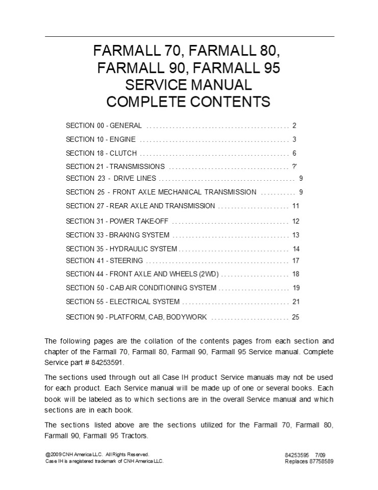
FARMALL 70, FARMALL 80,
FARMALL 90, FARMALL 95 SERVICE MANUAL COMPLETE
CONTENTS
- SECTION 00 - GENERAL .............................
............... 2 - SECTION 10 - ENGINE ..............................
................ 3 - SECTION 18 - CLUTCH ..............................
................ 6 - SECTION 21 - TRANSMISSIONS .......................
.............. ?' - SECTION 23 - DRIVE LINES .........................
................. 9 SECTION 25 - FRONT AXLE
MECHANICAL TRANSMISSION ........... 9 SECTION 27
- REAR AXLE AND TRANSMISSION .....................
. 11 - SECTION 31 - POWER TAKE-OFF ......................
.............. 12 - SECTION 33 - BRAKING SYSTEM ......................
.............. 13 - SECTION 35 - HYDRAULIC SYSTEM ....................
.............. 14 - SECTION 41 - STEERING ............................
................ 17 SECTION 44 - FRONT AXLE AND
WHEELS (2WD) ..................... 18 - SECTION 50 - CAB AIR CONDITIONING SYSTEM
...................... 19 SECTION 55 - ELECTRICAL
SYSTEM ................................. 21 - SECTION 90 - PLATFORM, CAB, BODYWORK
........................ 25 - The following pages are the collation of the
contents pages from each section and chapter of
the Farmall 70, Farmall 80, Farmall 90, Farmall
95 Service manual. Complete Service part
84253591. - The sections used through out all Case IH product
Service manuals may not be used for each product.
Each Service manual will be made up of one or
several books. Each book will be labeled as to
which sections are in the overall Service manual
and which sections are in each book. - The sections listed above are the sections
utilized for the Farmall 70, Farmall 80, Farmall
90, Farmall 95 Tractors.
_at_ 2009 CNH America LLC. All Rights Reserved. Case
IH is a registered trademark of CNH America LLC.
84253595 7/09 Replaces 87758589
2
SECTION 00 GENERAL CHAPTER 1 SECTION 00 -
GENERAL Chapter 1 - General CONTENTS
Description Page General Instructions
..................................................
......... 3 Important Notice .....................
...................................... 3 Shimming
..................................................
............... 3 Rotating Shaft Seals
..................................................
..... 3
Section
O Rings ..........................................
...................... 3 Sealers
..................................................
................. 3 Bearings .....................
.............................................
3 Spring Pins ....................................
.......................... 3 Precautionary Notice
..................................................
..... 4 Equipment Notice .........................
................................. 4 Spare Parts
Notice ...........................................
.............. 4 General Notices
..................................................
......... 4 Health and Safety ....................
.........................................
5 Health and Safety Precautions
...............................................
5 General Workshop Tools and Equipment
..................................... 11 Legal
Aspects ..........................................
.................. 11 Lubricants and Greases
..................................................
. 11 Precautionary Statements ....................
................................. 15 Personal
Safety ...........................................
................... 15 Machine Safety
..................................................
............ 15 Information ......................
............................................
15 Safety ........................................
.............................. 16 The Tractor
..................................................
............ 16 Driving the Tractor
..................................................
...... 16 Operating the Tractor
..................................................
.... 16 Operating the PTO ........................
................................ 17 Servicing the
Tractor ..........................................
............ 17 Diesel Fuel ......................
........................................ 18 ROPS
..................................................
................. 18 Ecology and the Environment
..................................................
19 Precautions ..................................
............................ 19 Minimum Hardware
Tightening Torques ...............................
.......... 20 Consumables ........................
........................................ 23
3
SECTION 00 GENERAL CHAPTER 1 GENERAL
INSTRUCTIONS
IMPORTANT NOTICE All maintenance and repair
operations described in this manual should be
carried out exclusively by the authorized
workshops. All instructions detailed should be
carefully observed and special equipment
indicated should be used if necessary.
- Take care to insert the seal perpendicular to its
seat while you are pressing it. Once the seal is
settled, ensure that it contacts the thrust
element, if required
- To prevent damaging the sealing lip against the
shaft, place a suitable protection during
installation.
Everyone who carries out service operations
described without carefully observing these
direc- tives will be directly responsible for
resulting consequences.
O RINGS Lubricate the O rings before inserting
them into their seats. This will prevent the O
rings from roll over and twisting during
mounting, which will jeopardize sealing.
SHIMMING At each adjustment, select adjusting
shims, measure them individually using a
micrometer and then sum up recorded values. Do
not rely on measuring the whole shimming set,
which may be incorrect, or on the rated value
indicated for each shim.
- SEALERS
- Apply silicone/gasket eliminator over the mating
surfaces marked with an X. - Before applying the sealer, prepare the surface
as follows - remove possible scales using a metal brush
ROTATING SHAFT SEALS To correctly install
rotating shaft seals, observe the following
instructions
- thoroughly degrease the surfaces using one of
the following cleaning agents trichlorethylene,
diesel fuel or a water and soda solution.
- Let the seal soak into the same oil as it will
seal for at least half an hour before mounting - Thoroughly clean the shaft and ensure that the
shaft working surface is not damaged - Place the sealing lip towards the fluid. In case
of a hydrodynamic lip, consider the shaft
rotation direction and orient grooves in order
that they deviate the fluid towards the inner
side of the seal - Coat the sealing lip with a thin layer of
lubricant (oil rather than grease) and fill the
gap between the sealing lip and the dust lip of
double lip seals with grease - Insert the seal into its seat and press it down
using a flat punch. Do not tap the seal with a
hammer or a drift
BEARINGS It is advisable to heat the bearings to
80 to 90C (176 to 194F) before mounting them
on their shafts and cool them down before
inserting them into their seats with external
tapping.
SPRING PINS When mounting split socket spring
pins, ensure that the pin notch is oriented in
the direction of the effort to stress the pin.
Spiral spring pins should not be oriented during
installation.
4
https//www.ebooklibonline.com Hello dear
friend! Thank you very much for reading. Enter
the link into your browser. The full manual is
available for immediate download. https//www.ebo
oklibonline.com
5
- SECTION 00 GENERAL CHAPTER 1
- PRECAUTIONARY NOTICE
- Only authorized workshops should carry out
maintenance and repair operations on the tractor,
or tractor compo- nents. Carefully observe all
instructions, safety precautions, and the use of
equipment such as special tools, as detailed in
this manual. Damage to the tractor, or injury to
personnel is the direct responsibility of anyone
who fails to observe these precautions. - EQUIPMENT NOTICE
- The equipment proposed in this manual is
- Designed and studied expressly for use on Case IH
tractors - Necessary for adequate and reliable repair of the
tractor - Strictly tested for the efficient and long
lasting life cycle of the tractor - SPARE PARTS NOTICE
- Genuine CASE IH spare parts guarantee the same
quality, safety and life cycle as original
components. These parts bear the logo. - GENERAL NOTICES
- In this manual, the description FRONT, REAR,
RIGHT-HAND and LEFT-HAND refer to the view
seen by the operator while in the operator's
seat, looking in the direction in which the
tractor normally moves. - Wear limits detailed in this manual, although
advised, are not binding.
6
SECTION 00 GENERAL CHAPTER 1 HEALTH AND
SAFETY CONTENTS Description Page HEALTH AND
SAFETY PRECAUTIONS ...............................
.......................... 5 ACIDS AND ALKALIS
..................................................
....................... 6 ADHESIVES AND SEALERS -
see Fire .........................................
................ 6 ANTIFREEZE - see Fire,
Solvents e.g. Isopropanol, Ethylene Glycol,
Methanol. ......................6 ARC WELDING -
see Welding.......................................
........................... 7 BATTERY ACIDS - see
Acids and Alkalis. ...............................
........................ 7 BRAKE AND CLUTCH
FLUIDS (Polyalkylene Glycols) see Fire.
................................... 7 BRAZING
see Welding. .....................................
................................. 7 CHEMICAL
MATERIALS - GENERAL - see Legal Aspects.
........................................ 7 DO'S
..................................................
..................................... 7 DO NOTS
..................................................
................................. 8 CORROSION
PROTECTION MATERIALS see Solvents, Fire.
.................................... 8 DUSTS
..................................................
................................... 8 ELECTRIC
SHOCK ............................................
............................... 8 EXHAUST FUMES
..................................................
......................... 9 FIBER INSULATION -
see Dusts. .......................................
....................... 9 FIRE - see Welding,
Foams, Legal Aspects. ............................
......................... 9 FIRST AID
..................................................
................................ 9 FOAMS
Polyurethane see Fire. .........................
................................... 9 FUELS see
Fire, Legal Aspects, Chemicals General,
Solvents. ................................ 10 GAS
CYLINDERS see Fire. ............................
.................................... 10 GENERAL
WORKSHOP TOOLS AND EQUIPMENT .....................
........................ 11 LEGAL ASPECTS
..................................................
......................... 11 LUBRICANTS AND
GREASES ..........................................
...................... 11 PAINTS see Solvents
and Chemical Materials General.
....................................... 12 SOLDER
- see Welding. ...................................
................................. 12 SOLVENTS -
see Chemical Materials - General Fuels
(Kerosene), Fire. ........................... 13
SUSPENDED LOADS ..................................
..................................... 13 WELDING
- see Fire, Electric Shock, Gas Cylinders.
............................................ 13
HEALTH AND SAFETY PRECAUTIONS Many of the
procedures associated with vehicle maintenance
and repair involve physical hazards or other
risks to health. This section lists, alphabeti-
cally, some of these hazardous operations and the
materials and equipment associated with them. The
precautions necessary to avoid these hazards
are identified.
The list is not exhaustive and all operations and
procedures and the handling of materials, should
be carried out with health and safety in mind.
7
SECTION 00 GENERAL CHAPTER 1
6
ACIDS AND ALKALIS see Battery acids,
e.g. caustic soda, sulfuric acid. Used in
batteries and cleaning materials. Irritant to the
skin, eyes, nose and throat. Causes burns.
Provide adequate ventilation and avoid skin and
eye contact. Follow manufacturers instructions.
Anaerobic, Cyanoacrylate and other Acrylic
Adhesives Many are irritant, sensitizing or
harmful to the skin. Some are eye irritants.
Avoid splashes to the skin, eyes and clothing.
Wear suitable protective gloves and goggles. Can
destroy ordinary protective clothing. Do not
breathe mists.
Skin and eye contact should be avoided and the
manufacturers instructions followed.
Ensure access to water and soap is readily
available for splashing accidents.
Cyanoacrylate adhesives (superglues) must not
contact the skin or eyes. If skin or eye tissue
is bonded cover with a clean moist pad and get
medical attention. do not attempt to pull tissue
apart. Use in well ventilated areas as vapors can
cause irritation of the nose and eyes.
ADHESIVES AND SEALERS see Fire Highly Flammable
and combustible.
Generally should be stored in No Smoking" areas
cleanliness and tidiness in use should be
observed, e.g. disposable paper covering benches
should be dispensed from applicators where
possible contain- ers, including secondary
containers, should be labelled.
For two-pack systems see Resin based adhesives/
sealers.
Isocyanate (Polyurethane) Adhesives/ Sealers
see Resin based Adhesives.
Solvent based Adhesives/Sealers - See Solvents.
Individuals suffering from asthma or respiratory
allergies should not work with or near these
materials as sensitivity reactions can occur.
Follow manufacturers instructions.
Water based Adhesives/Sealers
Any spraying should preferably be carried out in
exhaust ventilated booths removing vapors and
spray droplets from the breathing zone.
Individuals working with spray applications
should wear supplied air respirators.
Those based on polymer emulsions and rubber
lattices may contain small amounts of volatile
toxic and harmful chemicals. Skin and eye contact
should be avoided and adequate ventilation
provided during use.
ANTIFREEZE see Fire, Solvents e.g. Isopropanol,
Ethylene Glycol, Methanol. Highly Flammable and
Combustible.
Follow manufacturers instructions.
Resin based Adhesives/Sealers - e.g. epoxide and
formaldehyde resin based.
Used in vehicle coolant systems, brake air
pressure systems, screenwash solutions.
Mixing should only be carried out in well
ventilated areas as harmful or toxic volatile
chemicals may be released. Skin contact with
uncured resins and hardeners can result in
irritation dermatitis and absorption of toxic or
harmful chemicals through the skin. Splashes can
damage the eyes.
Vapors given off from coolant antifreeze (glycol)
arise only when heated.
Antifreeze may be absorbed through the skin in
toxic or harmful quantities. Antifreeze if
swallowed is fatal and medical attention must be
found immediately.
8
SECTION 00 GENERAL CHAPTER 1 y
ARC WELDING see Welding.
The effects of excessive exposure to chemicals
may be immediate or delayed briefly experienced
or permanent cumulative superficial life
threatening or may reduce life-expectancy.
BATTERY ACIDS - see Acids and Alkalis. Gases
released during charging are explosive. Never use
naked flames or allow sparks near charging or
recently charged batteries.
DO'S Do remove chemical materials from the skin
and clothing as soon as practicable after
soiling. Change heavily soiled clothing and have
it cleaned.
BRAKE AND CLUTCH FLUIDS (Polyalkylene Glycols)
see Fire. Combustible.
Do carefully read and observe hazard and
precaution warnings given on material containers
(labels) and in any accompanying leaflets, poster
or other instructions. Material health and safety
data sheets can be obtained from Manufacturers.
Splashes to the skin and eyes are slightly
irritating. Avoid skin and eye contact as far as
possible. Inhalation of vapor hazards do not
arise at ambient temperatures because of the very
low vapor pressure.
Do organize work practices and protective
clothing to avoid soiling of the skin and eyes
breathing vapors/aerosols/dusts/fumes inadequate
container labelling fire and explosion hazards.
BRAZING see Welding.
CHEMICAL MATERIALS - GENERAL - see Legal
Aspects. Chemical materials such as solvents,
seaters, adhesives, paints, resin foams, battery
acids, antifreeze, brake fluids, oils and grease
should always be used with caution and stored and
handled with care. They may be toxic, harmful,
corrosive, irritant or highly flammable and give
rise to hazardous fumes and dusts.
Do wash before job breaks before eating,
smoking, drinking or using toilet facilities when
handling chemical materials.
Do keep work areas clean, uncluttered and free of
spills.
Do store according to national and local
regulations.
Do keep chemical materials out of reach of
children.
9
SECTION 10 ENGINE CHAPTER 1 SECTION 10 -
ENGINE Chapter 1 - Engine (FSC) CONTENTS
Description Page Special Tools ...................
...............................................
2 Troubleshooting ................................
............................... 3 Overhaul
..................................................
.................... 7 Removal ...................
................................................
7 Installation ...................................
............................ 25
Section
10 001 10
10
SECTION 10 ENGINE CHAPTER 1 OVERHAUL
- Op. 10 001 10 REMOVAL
- DANGER
- Lift and handle all heavy parts using suitable
lifting equipment. - Make sure that assemblies or parts are supported
by - means of suitable slings and hooks. Check that no
one is in the vicinity of the load to be lifted. - CAUTION
- Always use appropriate tools to align fixing
holes. NEVER USE FINGERS OR HANDS. - Disconnect the battery negative lead (1).
- Drain the oil from the transmission-gearbox
housing. - Drain the cooling system.
1
4. Remove the exhaust pipe, attach lifting
chains (2) to the hood (1) and attach the chain
to the hoist.
2
11
8
SECTION 10 ENGINE CHAPTER 1
5. Disconnect the electrical connection (1) of
hood.
6. Detach the gas struts (1) from the hood.
4
7. Remove the four hood hinge bolts (1) and lift
the hood clear.
1
5
12
SECTION 10 ENGINE CHAPTER 1 8. Remove the
three retaining bolts (1) and the guard (2) on
the right-left hand side of the fan.
6
9. Unscrew the nut (1) from the weight retaining
pin. Remove the weights from the front support.
10. Unscrew the front central and rear retaining
bolts on the front axle shaft guard, then remove
the guard (1).
0 1 25038
8
13
10 SECTION 10 ENGINE CHAPTER 1
11. Remove the circlip (2) and move the front
sleeve (1) in the direction indicated by the
arrow until it is released from the groove on the
front axle.
25039
9
12. Remove the circlip (2) and move the rear
sleeve (1) in the direction indicated by the
arrow until it is released from the groove on the
drive.
10
13. Remove the propeller shaft central support
(1) retaining bolts and extract the shaft
together with the support.
11
14
SECTION 10 ENGINE CHAPTER 1 14. Dicconnect
the pressure pipe connection (1) of the lift pump.
12
15. Disconnect the delivery lines of both
hydraulic lift pump (1) and hydrostatic steering
pump (2).
13
16. Detach the cab heating pipes (1) and (2).
14
15
12 SECTION 10 ENGINE CHAPTER 1 17. Detach the
cab air-conditioning pipes (1) and (2).
15
18. Extract the plastic fasteners (2) and detach
the diesel recovery pipe (3) and delivery pipe
(4) to the diesel pump (1).
16
19. Remove two metal clamps (1) and the rigid
pipe of drawing oil from the transmission housing
via lift pump.
1
17
16
SECTION 10 ENGINE CHAPTER 1 20. Remove the
electrical connection from the brake fluid
reservoir and take the brake fluid reservoir (1)
from the bracket.
18
21. Disconnect the steering oil delivery and
return hoses (1) and (2). Disconnect the steering
cylin- der lines (3) and (4).
19
22. Disconnect the delivery and return lines (1)
to the power steering cylinders.
20
17
14 SECTION 10 ENGINE CHAPTER 1 23. Disconnect
rear brakes oil distribution connec- tion pipes
(1) and (2).
21
24. Disconnect brake distributor valve
connections (1) and (2).
22
25. Disconnect A/C compressor inlet (1) and
outlet (2) hoses.
23
18
SECTION 10 ENGINE CHAPTER 1
15
26. Remove the fusebox (1) from the hood support.
24
27. Remove the electrical oil pressure switch (1).
25
28. Remove the electrical connections of coolant
temperature sender (1).
26
19
16 SECTION 10 ENGINE CHAPTER 1 29. Remove the
electrical connection of pump cut- out solenoid
sender (1) and hydrostatic steering pump oil
pressure switch (2).
27
- Remove the retaining retaining clips (1) and de-
tach the flexible cables governing the hand
throttle and pedal throttle. - Remove the retaining clip (2) and detach the
throttle control tierod connected to the
injection pump.
28
32. Disconnect the electrical connection (1)
between the cab and the engine.
29
20
SECTION 10 ENGINE CHAPTER 1
IT
33. Disconnect the electrical connections from
start- er motor (1).
30
34. Disconnect the electrical connections from
alter- nator (1).
31
35. Disconnect the electrical connection of water
in fuel sensor (1).
32
21
18 SECTION 10 ENGINE CHAPTER 1 36. Disconnect
the electrical connections of dryer fil- ter
sensor (1).
37. Remove the electrical connection (1), air
filter clogging sensor (2) and AC compressor
electri- cal connection (3).
34
38. Remove the two retaining bolts and the
support together with relays protecting system
(1).
35
22
s
SECTION 10 ENGINE CHAPTER 1
39. Remove the two connectors of the brake lights
switch (1).
36
40. Loosen the corresponding retaining clamps and
extract the pipes (1), (2), (3) and (4).
37
41. Loosen the corresponding retaining bolts and
remove the bracket (1).
38
23
20 SECTION 10 ENGINE CHAPTER 1 42. Hitch the
engine to the hoist with the chains an- choring
it to the attachments on the engine.
39
43. Position the movable tool for dismantling
tractors 380000569 with the bracket 380000500 and
adapter plate 380000844 under the engine and
place a wooden block in between the points of
contact between the tool and tractor.
40
44. Extract the differential lock pedal retaining
pin from the drive shaft (1), remove the pedal
and footboard (2).
41
24
21
SECTION 10 ENGINE CHAPTER 1
45. Unscrew the nuts (1) and the bolts securing
the engine to the transmission. Access is through
the two slots in the cab floor.
42
46. Remove the remaining six retaining bolts at
the bottom and side.
43
47. Seperate the engine from the transmission
with the tool 380000569.
44
25
22 SECTION 10 ENGINE CHAPTER 1 48. Remove the
spacer located between the engine and the
transmission.
45
49. Insert the fixed under the balast support and
se- cure the front wheels with wooden blocks.
46
50. Loosen the corresponding retaining clamp (1)
and extract the pipes. And remove the bracket (2).
47
26
23
SECTION 10 ENGINE CHAPTER 1
51. Remove the hood support (1).
48
52. Loosen the retaining clamp and extract the
pipe (1) joining the coolant pump to the bottom
of the radiator.
49
53. Position a fixed stand (3) under the support
of the groove (1) of the front axle drive placing
a wood- en plug (2) between the parts (3) and (1).
2 3 MDF1783A
50
27
24 SECTION 10 ENGINE CHAPTER 1 54. Remove the
four bolts (2) fastening the front axle support
(1) to the engine (3).
51
ss Insert the hooks of the lifting chains (1) in
the eye- lets shown in the figure, afterwards
tensioning the chains with the hoist.
52
- Detach the engine (2) from the front axle (3),
try- ing to avoid incorrect operations with the
hoist so as not to let the engine fan damage the
fins of the radiator (1), left on the axle (3). - Then rest the engine on a platform support.
MDF1787A
53
28
SECTION 10 ENGINE CHAPTER 1 25
INSTALLATION
- Also apply LOCTITE sealing compound on the clutch
overdrive casing surfaces. - Position wooden blocks under the rear wheels,
make sure that the handbrake is fully applied and
that all fixed and mobile stands are safely
positioned. - The installation phase described here requires
the presence of two or three workers to use the
movable tool for dismantling tractors 380000569
to move the engine/front axle assembly close to
the overdrive clutch casing. - In the phase of installing the engine/front axle
assembly to the overdrive clutch casing, it is
necessary to push on the front wheels, taking
great care in the end phase of coupling over both
the pipes and the cables/electrical connections
to prevent crushing between the two bodies.
During this phase, it is moreover necessary to
turn the crankshaft with the aid of the radiator
cooling fan to help the coupling between the
sleeve and the drive shaft. - Secure both assemblies by tightening all the
bolts locking the engine to the overdrive clutch
casing. - Remove the U-bolt previously fitted under the
clutch casing and recover the movable tool for
dismantling tractors 380000569. - Fit the electric cable connected to the
fuse-holder box and the retaining nut. - Working from the side of the starter motor, fit
the protective cable housing and the retaining
nut. - Fit the electrical connections installed on the
brake pump and on the brake fluid reservoir. - Refit the power steering piping on the engine and
reconnect the electrical connections to the
pressure switch. - Refit the power steering return pipe with its
bracket and retaining bolt. - Refit the brake piping support and the two
retaining bolts. - Refit the condenser, air cooler and radiator
pipes.
CAUTION Always use appropriate tools to align
fixing holes. NEVER USE FINGERS OR HANDS.
- Apply the torque settings listed at FSC Engines
Repair Manual (Print No 87736548A). - Insert the three hooks of the chain in the
eyelets on the engine and, using the hoist, lift
the assembly off the platform support. - Position the engine on the front axle, trying to
avoid incorrect operations with the hoist so as
not to let the engine fan damage the fins of the
radiator, then join the two assemblies together
with the four retaining bolts. - Reposition the movable tool for dismantling
tractors 380000569 under the engine and place a
wooden block in between the point of contact
between the tool and engine. - With the aid of the hoist, place the engine on
the tool 380000569 and remove the lifting eyelet
previously fitted on the front of the engine. - Remove the fixed stand previously positioned
under the support of the groove of the drive of
the front axle and the wooden plug. - Refit the pipe joining the coolant pump to the
bottom of the radiator and the associated
retaining clamp. - Refit the oil vapour suction pipe, filter/intake
manifold connecting pipe and the pipe
connecting the radiator at the top to the
thermostat valve, reinstalling the associated
retaining clamps. - 9. Fit the leftright hand side guard of the
engine fan and the three retaining bolts.
4.
8.
- Remove the fixed U-bolt fitted beforehand under
the ballast support and the two wooden wedges
locking the front wheels. - Remove the old sealing compound from both
surfaces of the spacer between the engine and the
overdrive clutch housing, and do the same also on
the contact surface of the overdrive clutch
housing and on that of the engine. - Apply LOCTITE sealing compound on the
engine/spacer contact surfaces and fit the
spacer on the stud bolts screwed into the engine.
29
26 SECTION 10 ENGINE CHAPTER 1
- Refit the dryer filter together with its support
and piping, tightening the two retaining bolts. - Refit the hood support, tightening the retaining
bolts. - Refit the support with the fuseholder box on the
hood support, tightening the two retaining bolts. - Refit the support together with the relays
protecting the system on the hood support,
fitting the two retaining bolts. - Refit the brake fluid reservoir onto the support
and the two retaining clips. - T . Refit the silencer together with the exhaust
pipe. - Secure the silencer to the exhaust manifold with
the four nuts and connect the air filter dust
extractor pipe to the silencer exhaust, inserting
the retaining clamp. - Refit the three rear retaining bolts of the
exhaust - silencer.
- Fit the cab heater delivery and return pipes and
insert the associated clamps. - as Refit the fitting of the hose delivering
power steering oil to the hydraulic cylinders
governing the front wheel steering. - Install the flexible cables governing the hand
and pedal throttle, inserting the retaining
clips. - Reconnect the throttle control tierod to the
injection pump, inserting the retaining clip. - Working from inside the cab, fit the four plugs
to gain access to the upper bolts securing the
engine, located at the base of the steering
column. - Refit the pedal on the differential lock drive
shaft, the retaining pin and the footboard. - Refit the two right and lefthand dashboard
panels and the relevant four fixing knobs.
- Refit the two power steering cylinder oil
delivery and return hoses. - Install the electrical connections between the
cab and the engine. - Reconnect the diesel delivery and return pipes
to the diesel pump and install the relevant
plastic fasteners. - Working on the left-hand side of the engine,
install the lift pump draw pipe and tighten the
retaining bolts. - Install the delivery pipe of the services pump on
the right-hand side of the engine and tighten its
fitting. - Refit the rigid pipe for drawing oil from the
transmission and the two metal clamps. - Refit the power steering/four-wheel drive drain
pipe on both the left and righthand sides of
the engine. - Refit the lift pump draw pipe and lock the
retaining bolts. - Refit the propeller shaft with its central
support and the retaining bolts. - Refit the front axle drive shaft guard,
tightening the front, central and rear retaining
bolts. - Refit the front ballast together with the support
and insert the retaining pin and the split pins. - Install the fitting of the cab heater radiator
coolant return pipe connected to the bottom of
the coolant pump and refill the engine coolant. - Refit the guard on the right-hand side of the
fan, tightening the three retaining bolts. - Refill the transmissiongearbox housing with oil.
- Install the hood. Reconnect the battery negative
lead.
30
SECTION 10 ENGINE CHAPTER 2
15
SECTIONAL VIEWS
1 View of Farmall 90 tractor engines of 65 kW (88
HP) and Farmall 95 of 70 kW (95 HP)
31
16
SECTION 10 ENGINE CHAPTER 2
2
Lubrication diagram for engines mod. Farmall 90
and Farmall 95
Forcedcirculation lubrication is accomplished by
the following components
- oil pressure control valve incorporated in the
cooler assembly - bypass valve to cut off clogged oil filter,
incorpo- rated in the cooler assembly - cartridge oil filter.
oil pump, housed at the front of the
crankcase, driven by the grooved bushing keyed
onto the shank of the crankshaft - water / oil
cooler, housed in the crankcase
32
f7
SECTION 10 ENGINE CHAPTER 2
Cool
ant recirculating in the engine Coolant entering
the pump MIF1099A
3
Cooling system diagram
The forced circulation, closedcircuit engine
cooling system is composed of the following
components a lubricating oil cooler
- a centrifugal coolant pump housed at the front
of the crankcase - a thermostat valve governing coolant circulation.
33
18
SECTION 10 ENGINE CHAPTER 2
4 Detail of cylinder head with valve seats fitted
in engines mod. Farmall 90, Farmall 95
- Exhaust manifold
- Intake manifold
- Air heater
- Fitted valve seats
- Thermostat valve
- Injector
34
Suggest If the above button click is invalid.
Please download this document first, and then
click the above link to download the complete
manual. Thank you so much for reading
35
s
SECTION 10 ENGINE CHAPTER 2
10
MIF1102A
5
Additional counterweights
- Retaining bolts
- Support
- Retaining bolts
- Gear
- Balancing weight
- Half bearings
- Countershaft
- Gear
- Ring
10. O-Ring
36
https//www.ebooklibonline.com Hello dear
friend! Thank you very much for reading. Enter
the link into your browser. The full manual is
available for immediate download. https//www.ebo
oklibonline.com
Recommended
