
CASE IH JX1060C Tractor Service Repair Manual Instant Download - PowerPoint PPT Presentation
Title:
CASE IH JX1060C Tractor Service Repair Manual Instant Download
Description:
CASE IH JX1060C Tractor Service Repair Manual Instant Download – PowerPoint PPT presentation
Number of Views:0
Title: CASE IH JX1060C Tractor Service Repair Manual Instant Download
1
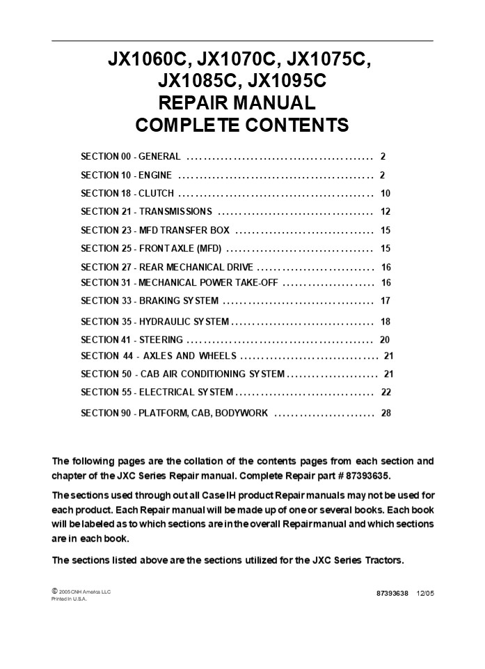
JX1060C, JX1070C, JX1075C, JX1085C, JX1095C
REPAIR MANUAL
COMPLETE CONTENTS
SECTION 00 - GENERAL .............................
............... 2 SECTION 10 - ENGINE
..............................................
2 SECTION 18 - CLUTCH ............................
.................. 10 SECTION 21 - TRANSMISSIONS
..................................... 12 SECTION
23 - MFD TRANSFER BOX ............................
..... 15 SECTION 25 - FRONT AXLE (MFD)
................................... 15 SECTION 27
- REAR MECHANICAL DRIVE ..........................
.. 16 SECTION 31 - MECHANICAL POWER TAKE-OFF
...................... 16 SECTION 33 - BRAKING
SYSTEM ....................................
17 SECTION 35 - HYDRAULIC SYSTEM
.................................. 18 SECTION 41
- STEERING .......................................
..... 20 SECTION 44 - AXLES AND WHEELS
................................. 21 SECTION 50
- CAB AIR CONDITIONING SYSTEM ....................
.. 21 SECTION 55 - ELECTRICAL SYSTEM
................................. 22 SECTION 90 -
PLATFORM, CAB, BODYWORK ........................
28
The following pages are the collation of the
contents pages from each section and chapter of
the JXC Series Repair manual. Complete Repair
part 87393635. The sections used through out
all Case IH product Repair manuals may not be
used for each product. Each Repair manual will
be made up of one or several books. Each book
will be labeled as to which sections are in the
overall Repair manual and which sections are in
each book. The sections listed above are the
sections utilized for the JXC Series Tractors.
? 2005 CNH America LLC Printed In U.S.A.
87393638 12/05
2
SECTION 00 - GENERAL - CHAPTER 1
1
SECTION 00 - GENERAL Chapter 1 -
General CONTENTS
Description Page General Instructions
..................................................
.......... 3 Health and Safety ...................
...........................................
5 Precautionary Statements .......................
.............................. 15 Safety
..................................................
.................... 16 Ecology and the
Environment ......................................
............ 19 Minimum Hardware Tightening
Torques .........................................
20 Federal Emissions Warranty ...................
................................ 22 California
Emission Control Warranty Statement
.................................. 23 Lubricants
and Fluids .......................................
.................. 25
Section
3
SECTION 00 - GENERAL - CHAPTER 1 WARNING WARNING
2
All maintenance and repair work described in
this manual must be performed exclusively by
CASE IH service technicians in strict accordance
with the instructions given and using any
specific tools necessary.
The Manufacturer and all organizations belong-
ing to the Manufacturer's distribution network,
including but not restricted to national,
regional or local distributors, will accept no
responsibility for personal injury or damage to
property caused by abnormal function of parts
and/or compo- nents not approved by the
Manufacturer, including those used for
maintenance and/or repair of the product
manufactured or marketed by the Manufacturer. In
any case, the product manufactured or marketed
by the Manufacturer is covered by no guarantee
of any kind against personal injury or damage to
property caused by abnormal function of parts
and/or components not approved by the
Manufacturer.
WARNING
Anyone who performs the operations described
herein without strictly following the
instructions is personally responsible for
resulting injury or damage to property.
4
https//www.ebooklibonline.com Hello dear
friend! Thank you very much for reading. Enter
the link into your browser. The full manual is
available for immediate download. https//www.eb
ooklibonline.com
5
SECTION 00 - GENERAL - CHAPTER 1
3
GENERAL INSTRUCTIONS
IMPORTANT NOTICE All maintenance and repair
operations described in this manual should be
carried out exclusively by the authorised
workshops. All instructions detailed should be
carefully observed and special equipment
indicated should be used if necessary. Everyone
who carries out service operations described
without carefully observing these prescrip-
tions will be directly responsible of deriving
damages.
- Take care to insert the seal perpendicularly to
its seat while you are pressing it. Once the
seal is settled, ensure that it contacts the
thrust element, if required - To prevent damaging the sealing lip against the
shaft, place a suitable protection during
installation.
O RINGS Lubricate the O rings before inserting
them into their seats. This will prevent the O
rings from roll over and twisting during
mounting, which will jeopardize sealing.
SHIMMING At each adjustment, select adjusting
shims, measure them individually using a
micrometer and then sum up recorded values. Do
not rely on measuring the whole shimming set,
which may be incorrect, or on the rated value
indicated for each shim.
SEALERS Apply silicone/gasket eliminator over the
mating surfaces marked with an X. Before
applying the sealer, prepare the surface as
follows
ROTATING SHAFT SEALS To correctly install
rotating shaft seals, observe the following
instructions
- remove possible scales using a metal brush
- thoroughly degrease the surfaces using one of
the following cleaning agents trichlorethylene,
diesel fuel or a water and soda solution.
- Let the seal soak into the same oil as it will
seal for at least half an hour before mounting - Thoroughly clean the shaft and ensure that the
shaft working surface is not damaged - Place the sealing lip towards the fluid. In case
of a hydrodynamic lip, consider the shaft
rotation direction and orient grooves in order
that they deviate the fluid towards the inner
side of the seal - Coat the sealing lip with a thin layer of
lubricant (oil rather than grease) and fill the
gap between the sealing lip and the dust lip of
double lip seals with grease - Insert the seal into its seat and press it down
using a flat punch. Do not tap the seal with a
hammer or a drift
BEARINGS It is advisable to heat the bearings to
80? to 90?C (176? to 194?F) before mounting them
on their shafts and cool them down before
inserting them into their seats with external
tapping.
SPRING PINS When mounting split socket spring
pins, ensure that the pin notch is oriented in
the direction of the effort to stress the
pin. Spiral spring pins should not be oriented
during installation.
6
SECTION 00 - GENERAL - CHAPTER 1
4
- GENERAL INSTRUCTIONS
- PRECAUTIONARY NOTICE
- Only authorized workshops should carry out
maintenance and repair operations on the tractor,
or tractor compo- nents. Carefully observe all
instructions, safety precautions, and the use of
equipment such as special tools, as detailed in
this manual. Damage to the tractor, or injury to
personnel is the direct responsibility of anyone
who fails to observe these precautions. - EQUIPMENT NOTICE
- The equipment proposed in this manual is
- Designed and studied expressly for use on Case IH
tractors - Necessary for adequate and reliable repair of the
tractor - Strictly tested for the efficient and long
lasting life cycle of the tractor - SPARE PARTS NOTICE
- Genuine CASE IH spare parts guarantee the same
quality, safety and life cycle as original
components. These parts bear the logo. - GENERAL NOTICES
- In this manual, the description FRONT, REAR,
RIGHT- HAND and LEFT- HAND refer to the view
seen by the operator while in the operators
seat, looking in the direction in which the
tractor normally moves. - Wear limits detailed in this manual, although
advised, are not binding.
7
SECTION 00 - GENERAL - CHAPTER 1
5
HEALTH AND SAFETY CONTENTS Description Page HEAL
TH AND SAFETY PRECAUTIONS ........................
................................. 5 ACIDS AND
ALKALIS ..........................................
............................... 6 ADHESIVES AND
SEALERS - see Fire ...............................
.......................... 6 ANTIFREEZE - see
Fire, Solvents e.g. Isopropanol, Ethylene Glycol,
Methanol. ...................... 6 ARC WELDING -
see Welding. .....................................
............................ 7 BATTERY ACIDS -
see Acids and Alkalis. ...........................
............................ 7 BRAKE AND CLUTCH
FLUIDS (Polyalkylene Glycols) - see Fire.
................................... 7 BRAZING -
see Welding. .....................................
................................. 7 CHEMICAL
MATERIALS - GENERAL - see Legal Aspects.
........................................ 7 DOS
..................................................
..................................... 7 DO NOTS
..................................................
................................. 8 CORROSION
PROTECTION MATERIALS - see Solvents, Fire.
.................................... 8 DUSTS
..................................................
................................... 8 ELECTRIC
SHOCK ............................................
............................... 8 EXHAUST FUMES
..................................................
......................... 9 FIBRE INSULATION -
see Dusts. .......................................
....................... 9 FIRE - see Welding,
Foams, Legal Aspects. ............................
......................... 9 FIRST AID
..................................................
................................ 9 FOAMS -
Polyurethane - see Fire. .........................
.................................... 9 FUELS -
see Fire, Legal Aspects, Chemicals - General,
Solvents. ................................ 10
GAS CYLINDERS - see Fire. ........................
........................................
10 GENERAL WORKSHOP TOOLS AND EQUIPMENT
............................................. 11
LEGAL ASPECTS ....................................
.......................................
11 LUBRICANTS AND GREASES ........................
........................................
11 PAINTS - see Solvents and Chemical Materials -
General. .......................................
12 SOLDER - see Welding. ........................
............................................
12 SOLVENTS - see Chemical Materials - General
Fuels (Kerosene), Fire. ..........................
. 13 SUSPENDED LOADS ............................
...........................................
13 WELDING - see Fire, Electric Shock, Gas
Cylinders. .......................................
..... 13
HEALTH AND SAFETY PRECAUTIONS Many of the
procedures associated with vehicle maintenance
and repair involve physical hazards or other
risks to health. This section lists, alphabeti-
cally, some of these hazardous operations and the
materials and equipment associated with them. The
precautions necessary to avoid these hazards are
identified. The list is not exhaustive and all
operations and procedures and the handling of
materials, should be carried out with health and
safety in mind.
8
SECTION 00 - GENERAL - CHAPTER 1
6
ACIDS AND ALKALIS -- see Battery acids, e.g.
caustic soda, sulfuric acid. Used in batteries
and cleaning materials. Irritant and corrosive to
the skin, eyes, nose and throat. Causes
burns. Avoid splashes to the skin, eyes and
clothing. Wear suitable protective gloves and
goggles. Can destroy ordinary protective
clothing. Do not breathe mists. Ensure access to
water and soap is readily available for
splashing accidents.
Provide adequate ventilation and avoid skin and
eye contact. Follow manufacturers instructions.
Anaerobic, Cyanoacrylate and other Acrylic
Adhesives Many are irritant, sensitizing or
harmful to the skin. Some are eye
irritants. Skin and eye contact should be avoided
and the manufacturers instructions
followed. Cyanoacrylate adhesives (super-
glues) must not contact the skin or eyes. If
skin or eye tissue is bonded cover with a clean
moist pad and get medical attention. do not
attempt to pull tissue apart. Use in well
ventilated areas as vapours can cause irritation
of the nose and eyes. For two- pack systems see
Resin based adhesives/ sealers.
ADHESIVES AND SEALERS -- see Fire Highly
Flammable, Flammable, combustible. Generally
should be stored in No Smoking areas
cleanliness and tidiness in use should be
observed, e.g. disposable paper covering benches
should be dispensed from applicators where
possible contain- ers, including secondary
containers, should be labelled. Solvent based
Adhesives/Sealers - See Solvents. Follow
manufacturers instructions. Water based
Adhesives/Sealers Those based on polymer
emulsions and rubber lattices may contain small
amounts of volatile toxic and harmful chemicals.
Skin and eye contact should be avoided and
adequate ventilation provided during use. Follow
manufacturers instructions. Resin based
Adhesives/Sealers - e.g. epoxide and
formaldehyde resin based. Mixing should only be
carried out in well ventilated areas as harmful
or toxic volatile chemicals may be
released. Skin contact with uncured resins and
hardeners can result in irritation dermatitis
and absorption of toxic or harmful chemicals
through the skin. Splashes can damage the eyes.
Isocyanate (Polyurethane) Adhesives/ Sealers --
see Resin based Adhesives.
Individuals suffering from asthma or respiratory
allergies should not work with or near these
materials as sensitivity reactions can
occur. Any spraying should preferably be carried
out in exhaust ventilated booths removing
vapours and spray droplets from the breathing
zone. Individuals working with spray
applications should wear supplied air
respirators.
ANTIFREEZE -- see Fire, Solvents e.g.
Isopropanol, Ethylene Glycol, Methanol. Highly
Flammable, Flammable, Combustible. Used in
vehicle coolant systems, brake air pressure
systems, screenwash solutions. Vapours given off
from coolant antifreeze (glycol) arise only when
heated. Antifreeze may be absorbed through the
skin in toxic or harmful quantities. Antifreeze
if swallowed is fatal and medical attention must
be found immediately.
9
SECTION 00 - GENERAL - CHAPTER 1
7
ARC WELDING -- see Welding.
The effects of excessive exposure to chemicals
may be immediate or delayed briefly experienced
or permanent cumulative superficial life
threatening or may reduce life- expectancy.
BATTERY ACIDS -- see Acids and Alkalis. Gases
released during charging are explosive. Never
use naked flames or allow sparks near charging
or recently charged batteries.
DOS Do remove chemical materials from the skin
and clothing as soon as practicable after
soiling. Change heavily soiled clothing and
have it cleaned. Do carefully read and observe
hazard and precaution warnings given on material
containers (labels) and in any accompanying
leaflets, poster or other instructions. Material
health and safety data sheets can be obtained
from Manufacturers. Do organise work practices
and protective clothing to avoid soiling of the
skin and eyes breathing vapours/aerosols/dusts/f
umes inadequate contain- er labelling fire and
explosion hazards. Do wash before job breaks
before eating, smoking, drinking or using toilet
facilities when handling chemical materials. Do
keep work areas clean, uncluttered and free of
spills. Do store according to national and local
regulations. Do keep chemical materials out of
reach of children.
BRAKE AND CLUTCH FLUIDS (Polyalkylene Glycols) --
see Fire. Combustible. Splashes to the skin and
eyes are slightly irritating. Avoid skin and eye
contact as far as possible. Inhalation of vapour
hazards do not arise at ambient temperatures
because of the very low vapour pressure.
BRAZING -- see Welding.
CHEMICAL MATERIALS - GENERAL -- see Legal
Aspects. Chemical materials such as solvents,
sealers, adhesives, paints, resin foams, battery
acids, antifreeze, brake fluids, oils and grease
should always be used with caution and stored
and handled with care. They may be toxic,
harmful, corrosive, irritant or highly
inflammable and give rise to hazardous fumes and
dusts.
10
SECTION 10 - ENGINE - CHAPTER 1
1
SECTION 10 - ENGINE Chapter 1 - Engine
(Three-Cylinder) CONTENTS
Description Page Specifications
..................................................
................ 2 Special Tools
..................................................
.............. 10 Tightening Torques
..................................................
......... 12 Sectional Views .....................
.........................................
13 Engine Troubleshooting ........................
............................... 15 Overhaul
..................................................
.................. 19 Engine .....................
.............................................
19 Removal .......................................
...................... 19 Installation
..................................................
.......... 20 Compression Test ...................
.................................. 21 Disassembly
..................................................
........ 22 Assembly .............................
............................... 32 Checks,
Dimensions and Repairs ...........................
................ 41 Cylinder Block
..................................................
...... 41 Crankshaft .............................
.............................. 43 Main Bearings
..................................................
...... 45 Flywheel ...............................
.............................. 46 Connecting Rods
..................................................
.... 47 Pistons ..................................
............................. 48 Valves
..................................................
............. 51 Tappets .........................
..................................... 51 Camshaft
..................................................
........... 52 Valve Timing ......................
.................................... 53 Cylinder
Head .............................................
........... 54 Valve Seats .......................
.................................... 55 Valve
Guides ...........................................
.............. 56 Injector Sleeves
..................................................
..... 59 Crankshaft Front Oil Seal
...............................................
61 Valve/Rocker Arm ..............................
....................... 63 Exhaust Pipe
..................................................
........... 65 Removal ...........................
..................................
65 Installation ..................................
.......................... 65
Section
10 001 10
10 001 30 10 001 54
10 101 53 10 101 60 10 102 70 10 106 12 10 254 44
11
2
SECTION 10 - ENGINE - CHAPTER 1
SPECIFICATIONS
Engine type
- Models JX1060C (Naturally Aspirated) ............................... 8035.05C/919
- Models JX1070C (Turbocharged) ................................... 8035.25R/919
- Models JX1075C (Turbocharged) ................................... 8035.25/919
Cycle ............................................................... diesel, 4- stroke
Injection ............................................................. direct
Number of on- line cylinders ............................................ 3
Piston diameter
- Models JX1060C ................................................. 104 mm (4.09 in)
- Models JX1070C ................................................. 104 mm (4.09 in)
- Models JX1075C ................................................. 104 mm (4.09 in)
Piston stroke ......................................................... 115 mm (4.53 in)
Total displacement
- Models JX1060C .................................................. 2931 cm3 (178.85 in3)
- Models JX1070C .................................................. 2931 cm3 (178.85 in3)
- Models JX1075C .................................................. 2931 cm3 (178.85 in3)
Compression ratio for Models JX1060C .................................. 171 naturally aspirated
Compression ratio for Models JX1070C, JX1075C ........................ 16.51 turbocharged
Maximum power
- Models JX1060C .................................................. gross 57 hp net 55 hp
- Models JX1070C .................................................. gross 70 hp net 67 hp
- Models JX1075C .................................................. gross 75 hp net 72 hp
Maximum power speed ................................................ 2300 rpm
Maximum speed no load ............................................... 2450 - 2500 rpm
Maximum torque speed for Models JX1060C ............................. 1400 rpm
Maximum torque speed for Models JX1070C ............................. 1400 rpm
Maximum torque speed for Models JX1075C ............................. 1400 rpm
Number of main bearings .............................................. 4
Sump pan ........................................................... structural, cast iron
Speedometer/tachometer ...........................
... Operating system ............................
........... Hour counter calibrated for engine
speed of ................
incorporated in control panel from gear on
camshaft 1800 rpm
(continued)
12
3
SECTION 10 - ENGINE - CHAPTER 1
Timing system overhead valves operated by tappets, rods and rocker arms via the camshaft located in the engine block the camshaft is driven by the crankshaft using helical gears
Intake - start before TDC. ................................... - end after BDC. ..................................... Exhaust - start before BDC. ................................... - end after TDC. ..................................... Valve- rocker arm clearance for timing check ............... Valve- rocker arm clearance (with engine cold) - intake ............................................. - exhaust ............................................ 12? 31? 50? 16? 0.45 mm (0.0177 in) 0.30 ? 0.05 mm (0.011 ? 0.0019 in) 0.30 ? 0.05 mm (0.011 ? 0.0019 in )
CRANKCASE/CYLINDER BLOCK DATA mm (in)
Cylinder Block ......................................... Internal diameter of cylinders ............................. Cylinder internal diameter oversizes ....................... Maximum permissible cylinder ovality or taper due to wear . . . Main journal half bearing seat diameter .................... Camshaft bushing seat diameter - front ............................................... - intermediate ....................................... - rear ............................................... Diameter of standard tappet bores in crankcase ............ Tappet oversizes ....................................... cast- iron monobloc with parent-bore cylinders, incorporating seatings for crank- shaft, camshaft and tappets 104.000 to 104.024 (4.0944 to 4.0954) (1) 0.4 to 0.8 (0.0157 to 0.0314) 0.12 (0.0047) 84.200 to 84.230 (3.3149 to 3.3161) 54.780 to 54.805 (2.1566 to 2.1576) 54.280 to 54.305 (2.1370 to 2.1379) 53.780 to 53.805 (2.1173 to 2.1183) 15.000 to 15.018 (0.5905 to 0.5912) 0.1 - 0.2 - 0.3 (0.0039 - 0.0078 - 0.0118)
(1) Measure in the area swept by piston rings,
both parallel and perpendicular to the crankshaft
axis.
13
SECTION 10 - ENGINE - CHAPTER 1
13
SECTIONAL VIEWS
1 2
7 6
3
4
5
25355
2
Longitudinal section of engine (models JX1060C)
- Rocker Shaft Pedestal Bolts
- Cylinder Head Bolts
- Flywheel Mounting Bolts
- Main Bearing Cap Bolts
- Big-end Cap Bolts
- Fan and Alternator Bolts
- Crankshaft Hub Retaining Nut
14
SECTION 10 - ENGINE - CHAPTER 1
19
OVERHAUL
Op. 10 001 10 ENGINE Removal
- DANGER
- Lift and handle all heavy parts using suitable
lifting equipment. - Make sure that assemblies or parts are supported
by means of suitable slings and hooks. Make sure
that no one is standing in the vicinity of the
load - to be lifted.
- WARNING
- Always use appropriate tools to align fixing
holes. NEVER USE YOUR FINGERS OR HANDS. - Carry out operation 18 110 10, Clutch Removal
(see Sect. 18). - Remove the clogged air filter sensor connection
(1).
27764
4
3. Disconnect the horn connection (1).
27765
5
15
20
SECTION 10 - ENGINE - CHAPTER 1
4. Loosen the clamps (1, 2 and 3) and remove the
inlet manifold.
27180
6
- Unscrew the band clamps and detach the upper
- (2) and lower radiator hoses, detach the radiator
bracket (1). - Position two fixed stands under the front axle
support and under the engine. Attach the chains
so that the engine is balanced during hoisting
and position two wood blocks between the support
and the front axle, to prevent oscillation.
27807
7
- Loosen the front axle support retaining bolts
(1). - Remove the engine from the axle- support unit.
- Installation
- WARNING
- Always use appropriate tools to align fixing
holes. NEVER USE YOUR FINGERS OR HANDS. - Apply the prescribed tightening torques. See the
Contents.
27808
- Install the front axle- support unit on the
engine. - Connect and secure the upper and lower radiator
hoses and the connecting bracket. - Install and secure the inlet manifold.
- Connect the horn and clogged air filter
connections. - Carry out operation 18 110 10, Clutch
Installation (see Sect. 18).
8
16
SECTION 10 - ENGINE - CHAPTER 1 21
Op. 10 001 30 Compression Test In case of poor
engine performance, in addition to checking the
fuel injection system (injection nozzles and
injection pump), also test the compression on
each cylinder.
- Turn the engine over a few times with the starter
motor in order to expel any carbon residue - Fit the dummy injector 380000617, in place of the
injector removed previously, interposing the
copper sealing washer - Connect the compression test instrument
380000303 and take readings while turning the
engine over with the starter motor. - On engines in perfect working order, with the
sump oil at approx. 40oC (104oF) at sea level
(760 mm 29.92 in. of mercury) and at an engine
speed of 200 to 280 rpm, the compression should
be 25 to 27 bar (369 to 398 psi). - Test the compression on the other cylinders,
repeating steps 4- 5- 6- 7, bearing in mind that - The minimum permissible compression on a used
engine is 21 bar (313 psi). - The maximum permissible compression differ- ence
between cylinders is 3 bar (43 psi). - Every 100 meters (109.36 yards) above sea level
corresponds to a reduction in compression by
approx. 1.
DANGER
Do not use matches, lighters, blow torches or any
form of naked flame as a source of light when
inspecting the engine due to the presence of
inflammable fluids and vapor.
Compression Ratio The compression ratio is a
measure of the quantity of air drawn into the
cylinder, and provides an indication of the
efficiency of the sealing elements in the
cylinder (piston rings and valves). Uniform
compression in all the cylinders ensures that
they all perform an equal amount of work,
provided that each cylinder is injected with the
same quantity of fuel at the right time. Low
compression not only reduces engine perfor-
mance, it also causes incomplete fuel combustion
due to the lack of available combustion air. The
engine therefore gives poor performance with
excessive fuel consumption and, consequently,
exhaust smoke and restriction of the exhaust
passages. As the compression ratio also varies
with the temperature of the engine (cold engines
produce lower compression values than hot
engines), the compression should only be tested
when the engine is at normal operating
temperature. Compression should be tested using
the compres- sion test kit 380000303, as follows
Uniform Compression Although high compression is
important, it is more important for smooth
engine running that compres- sion is uniform in
all cylinders. Low compression readings If
extremely low pressure readings are obtained on
one cylinder it is advisable to repeat the
test. Before testing this time, pour approx. one
spoonful of engine oil into the cylinder through
the injector bore. Turn over the engine a few
times to distribute the oil evenly over the
cylinder walls, and then repeat the test. If the
second test readings are significantly higher,
suspect worn piston rings, out- of- round or
damaged pistons or cylinders. If the second test
readings are not higher, the problem will be the
valves. On the other hand, if the second test
reading shows only a slight improvement, the
problem will be due to both the valves and the
rings.
- Run the engine until it reaches normal operating
temperature - Switch off the engine
- Disconnect the lead from the engine stop
electromagnet on the injection pump in order to
close the valve and block the flow of fuel to the
injectors - Remove the injector from the cylinder to be
tested
17
22
SECTION 10 - ENGINE - CHAPTER 1
Op. 10 001 54 Disassembly WARNING Handle all
parts carefully. Do not put your hands or
fingers between parts. Wear suitable safety
clothing - safety goggles, gloves and shoes. 1.
Disconnect the thermostarter union (2), the inlet
line retaining unions from the injection pump,
the injectors, and the piping (1).
27770
9
2. Disconnect the fuel filter lines (2) to the
injection pump and the support retaining bolts
(1). Remove the fuel filter.
27771
10
3. Disconnect the hydraulic piping (2) the oil
filter (1) retaining bolts complete with the
support, and remove from the engine.
27772
11
4. Remove the lift (2) and steering (1) hydraulic
pumps and remove the piping (3).
27773
12
18
SECTION 10 - ENGINE - CHAPTER 1
23
5. Unscrew the retaining bolts and remove the
starter motor (1).
27774
13
6. Unscrew the retaining bolts and remove the
cover (3), loosen the retaining nut (2) on the
injection pump (1) and remove from the opposite
side.
27775
14
7. Unscrew the retaining nuts and remove the fuel
pump (1).
27776
15
8. Unscrew the retaining bolts and remove the
exhaust muffler (1) complete with the vertical
pipe. On models with horizontal exhaust pipes,
remove when disassembling the engine.
27777
16
19
- 24 SECTION 10 - ENGINE - CHAPTER 1
- Unscrew the retaining bolts, remove the
alternator (1) and recover the drive belt. - Remove the engine oil filter (2).
27778
17
11. Unscrew the retaining bolts and remove the
exhaust manifold (1).
27779
18
12. Unscrew the retaining bolts and detach the
coolant pump hose(1).
27780
19
13. Unscrew the retaining bolts and detach the
coolant pump (1) complete with fan (2).
27781
20
20
SECTION 10 - ENGINE - CHAPTER 1
25
14. Unscrew the retaining bolts and detach the
coolant pump support (1).
27782
21
15. Unscrew the retaining bolts and disconnect
the thermostatic valve unit (2) complete with
bracket (1).
27783
22
16. Unscrew the retaining bolts and remove the
inlet manifold (1).
27784
23
- Remove the injector mounting nuts, the underly-
ing spherical washers, then the supports and the
injectors themselves. - Remove the rocker cover bolts (1), washers and
seals, and then the rocker cover (2) and the
gasket.
1 2 25098
24
21
26 SECTION 10 - ENGINE - CHAPTER 1 19. Remove the
rocker shaft retaining bolts (2), then remove
the entire rocker shaft assembly (1).
1
2
25099
25
20. Remove the valve collets (1) and extract the
pushrods (2).
2
1
25100
26
- Unscrew the cylinder head bolts (1) and remove
the head using a hoist and lifting hook
380000216. - Remove the cylinder head gasket.
1
25101
27
- Unscrew the sump pan retaining bolts and remove
the sump pan using a hoist, lifting hook
380000216 and lifting chain with eyeholes. - Remove the half- gaskets (1) and (3) between the
crankcase and sump pan and the gasket (2)
between the timing gear carrier and sump pan. - NOTE When reinstalling gaskets (1) and (2, fig.
28), apply RHODORSIL CAF1 silicone sealing
compound to the mating surfaces.
1 2 3 25104
28
22
SECTION 10 - ENGINE - CHAPTER 1 27
25. Remove the gasket (1) between the flywheel
carrier and the sump pan.
1 25105
29
26. Unscrew retaining bolts (1) and remove the
complete oil pump (non-turbo version shown).
1
25107
30
27. Unscrew the retaining bolts (2) and remove
the crankshaft pulley (1).
1 2 25108
31
23
28 SECTION 10 - ENGINE - CHAPTER 1 28.
Straighten the lock tab, securing the crankshaft
against rotation and unscrew nut (1).
1
25109
32
29. Pull the pulley hub off the crankshaft using
tool 380000226 (1) and recover the woodruff key.
1 25110
33
30. Unscrew the retaining bolt (1) and remove the
timing cover and gasket.
1 25111
34
31. Unscrew the retaining bolts and remove the
lift pump drive gear carrier (1).
1 25112
35
24
SECTION 10 - ENGINE - CHAPTER 1
29
32. Remove the circlip (1) and recover the thrust
washer and the intermediate gear (2)
2
1
25113
36
33. Unscrew the retaining bolts (1) and remove
the intermediate gear journal.
1 25114
37
34. Unscrew the retaining bolts (2) and withdraw
the camshaft (3) complete with the camshaft gear
(1) and the end plate (4).
1 2 3 4 25115
38
35. Remove the circlip (1) and the thrust washer,
and withdraw the gear with fuel supply pump
camshaft (2) from the opposite side.
1 2 25108
39
25
30 SECTION 10 - ENGINE - CHAPTER 1
36. Unscrew the retaining bolts (1) and remove
the timing gear case.
1 25109
40
- Replace the O- ring seal (1) installed in the
lift pump drive shaft lubrication line. - Remove the crankcase - timing gear case gasket.
1 25118
41
39. Rotate the engine through 90on the stand.
Unscrew the big- end cap bolts (2) and recover
the big- end caps (1) with their half shell
bearings.
1 2 25119
42
40. Slide the pistons (1), complete with rings,
wrist pins and connecting rods, out of the
cylinders.
1 25108
43
26
SECTION 10 - ENGINE - CHAPTER 1 31
- Rotate the engine on the stand through 90 back
to the horizontal position. Unscrew the flywheel
bolts and remove the flywheel with the aid of a
hoist and hook 380000216. - Unscrew the retaining bolts and remove the rear
oil seal carrier (1) complete with gasket.
1 25109
44
- Unscrew the main bearing cap bolts (1), and
remove the main bearing caps with relative
bearing shells, and recover the thrust washers
located on the penultimate main bearing, as
shown in the figure. - Lift the crankshaft clear of the crankcase using
a hoist and nylon sling. Recover the bearing
shells, thrust washers and tappets.
1 25122
45
- Rotate the engine through 180 on the stand
380000301 (2). Attach the lifting chain with eye
holes to the crankcase, as shown in the figure.
Raise the hook 380000216, unscrew the bolts
securing the crankcase to the stand (2) and
mounting bracket (3) from set 380000313. - Lift the engine clear of the stand.
- Unscrew the retaining bolts and remove the rear
crankcase housing (1) and its gasket.
1 3 2 25123
46
27
32
SECTION 10 - ENGINE - CHAPTER 1
- Assembly
- WARNING
- Handle all parts carefully, do not put your hands
or fingers between parts and use appropriate
tools to align fixing holes. - Wear the prescribed safety clothing, including
goggles, gloves and safety footwear. - Assemble the engine by performing the disassembly
procedures in reverse order, and with the
following requirements - Thoroughly clean all parts before assembling the
engine. - Apply the prescribed tightening torques. See
table of contents. - Replace all seals before assembling the engine.
- Before inserting rotating parts and seals in
seats, lubricate the parts with engine oil. - When installing the oil filter, lubricate the
seal with engine oil. - Crankshaft, Main Bearings and Thrust Rings
- Install the tappets in their crankcase bores.
- Lubricate the main bearing seats with engine oil
and install the half- shell bearings (3). - To facilitate installation, apply grease to the
thrust rings, then insert crankshaft
semi-circular thrust washers, 1.
1
3 2
25109
47
28
SECTION 10 - ENGINE - CHAPTER 1 33
4. Lubricate the upper surfaces of the main
bearing shells with engine oil and lower the
crankshaft (1) into position, taking care not to
dislodge the semi- circular thrust washers
installed previously.
1 24718
48
- Lubricate the crankshaft journals with engine oil
and install the main bearing caps (3) with the
half- shells (4), installing the top semi-
circular thrust washers (2) to the thrust
bearing cap (3). - Rotate the crankshaft (1) a few times to allow
the parts to settle into position. - Insert the main bearing cap bolts and screw in
until the head of the bolt is up against the cap.
1
2
3
4
25108
49
8. Tighten all cap bolts (1) to a torque of 80 Nm
(59 lb-ft).
1 24720
50
- Using tool 380000304 (2), tighten each cap bolt
- through a further 90?.
1 2 24744
51
29
34 SECTION 10 - ENGINE - CHAPTER 1
10. Check that the crankshaft endfloat does not
exceed the value specified. See the
Specifications.
24760
52
Rear Cover, Crankshaft Seal and Engine Flywheel
1 3 2 24752
- Install the rear oil seal carrier (3) with the
outer seal. Tighten the retaining bolts (2). See
Tightening Torques - refer to Contents.
Using a feeler gauge (1), check that the
crankshaft flange is centered in the carrier.
53
Oil leakage from the crankshaft rear oil seal
will result if the seal is not handled or
installed correctly. The correct handling and
installation procedures are as follows 1. The
seal that was originally installed had a 6mm
(0.236 in) gap, (1) between the seal housing (2)
and the molded plastic insert (3).
2 3
20026008
54
30
SECTION 10 - ENGINE - CHAPTER 1
35
IMPORTANT The seal is preassembled with a
protective molded plastic insert. Carefully
handle the seal by the molded plastic insert
only. The insert protects the seal from any
damage during parts stock and during
installation. The protective molded plastic
insert MUST NOT be removed or rotated in the
seal prior to installation. The insert should
only be removed after the new seal has been
completely installed as detailed in these
instructions.
- The machined sealing surface area of the
crankshaft MUST NOT be cleaned using any type of
abrasive paper. - The new seal lip should never be positioned in
the exact same location on the crankshaft as the
previous seal that was removed. This is to
prevent the new seal lip from riding in the wear
groove made by the previous seal lip. - The first replacement seal should be installed
with a gap (1) of 3.8 to 4 mm (0.150 to 0.157 in)
between the seal housing (2) and the molded
plastic insert (3).
2 3
20026009
55
5. The seal, complete with the insert, must only
be installed using the special made tools
described below.
20026010
NOTE The spacer is used for the correct
clearance gap of 3.8 to 4 mm (0.150 to 0.157
in). The installer bushing is used to install
the seal into the housing. (See dimensions for
the spacer and installer bushing as shown)
- 1. Spacer ID 135.5 to 136 mm (5.335 to 5.354
in) - Spacer Width 3.8 to 4 mm (0.150 to 0.157 in)
- Spacer OD 145 mm (5.709 in)
- Installer Bushing 115 mm (4.527 in)
- Installer Bushing Width 30 mm (1.181 in)
- Installer Bushing OD 129 mm (5.079 in)
56
31
36
SECTION 10 - ENGINE - CHAPTER 1
- Seal Installation
- Lightly oil the crankshaft seal area with new
engine oil. - Install the spacer onto the molded plastic
insert. Use the installed bushing to push the
seal into position in the seal housing. - Ensure that the seal is installed evenly around
the full circumference (the spacer should be
against the molded plastic insert and the
housing all the way around). - NOTE The molded plastic insert should not be
removed until the seal is correctly positioned. - IMPORTANT The engine MUST NOT be started within
24 HOURS of the seal installation and plastic
insert removal. This is required to allow the
seal to expand and settle onto the crankshaft
after the molded plastic insert is removed.
- Install the flywheel and tighten the retaining
bolts - to a torque of 40 Nm (30 lb-ft).
1 24762
57
- Using tool 380000304 (1), tighten each flywheel
bolt (2) through a further 60?.
1 2 24763
58
32
Suggest If the above button click is invalid.
Please download this document first, and then
click the above link to download the complete
manual. Thank you so much for reading
33
SECTION 10 - ENGINE - CHAPTER 1
37
Pistons with Rings, Pins, Connecting Rods, Big
End Caps and Bearings
- Lubricate pistons, rings and cylinders with
engine oil prior to fitting. - Using the piston ring pliers 380000221 install
the piston rings. Make sure that the piston ring
gaps are offset at 180?. - Install piston ring clamp 380000220 (1) to
compress the rings (2), making sure that the
piston ring gaps remain in the positions
specified in the previous point.
25163
59
- Insert the piston / connecting rod into the
cylinder, checking that the connecting rod
number corresponds with the cylinder number and
that the number stamped on the connecting rod is
facing away from the camshaft. - Install the big- end caps (1), complete with
shells, to the crankpins and tighten the cap
bolts (2) to a torque of 40 Nm (30 lb-ft).
2
1
25164
60
6. Using tool 380000304 (1), tighten each big-
end cap bolt (2) through a further 60o.
1
2
25165
61
34
https//www.ebooklibonline.com Hello dear
friend! Thank you very much for reading. Enter
the link into your browser. The full manual is
available for immediate download. https//www.eb
ooklibonline.com
Recommended
CrystalGraphics Presentations


