
Bobcat M600 Skid Steer Loader Service Repair Manual Instant Download - PowerPoint PPT Presentation
Title:
Bobcat M600 Skid Steer Loader Service Repair Manual Instant Download
Description:
Bobcat M600 Skid Steer Loader Service Repair Manual Instant Download – PowerPoint PPT presentation
Number of Views:0
Title: Bobcat M600 Skid Steer Loader Service Repair Manual Instant Download
1
(No Transcript)
2
0flTflTS DIESEL ENGINE SERVICE
.................... 143 - 217
DIESEL ENGINES
DEUTZENGINESERVICE. . . . . . . . . . . .
. . PETTERENGINESERVICE . ... ... . ...
143-192 193-213
DR IVE SYSTEM SERVICE ...................
.10 - 37
ELECTR IC MOTOR SERVICE ................... 219 -
222
DR IV E SYSTEM
7- 142 105 - 126 127 - 138 75 - 103
GASOLINE LP ENG INE SERVICE .............. KOH
LER ENG I NE SER VICE ONAN ENG IN E SE RVICE
. WISCONSI N ENG INE SERVICE . .
ELECTRIC MOTORS
GENERAL MAINTENANCE ..................... 7 - 9
GENERAL SERVICE INFORMATION .................
HYDRAULIC SYSTEM SERVICE
.................. 38 - 70
GASOL INE LP ENGINES
LOADER OPERATION ....................... 1 - 6
GENERAL MAINT
G EN. SE R V I NFO
HYDRAU LIC SYSTEM
OPE RATION
3
DRIVE SYSTEM SERVICE
Axle Repair ...................... 24 - 26
Clutch Adjustment .................... 11
Clutch Bearing Repair ................... 17
Clutch Repair 12 - 17
Drive Belt ... 18 19
Drive Chain Adjustment .................. 29 - 31
Driven Sheave Alignment 22 - 23
Driven Sheave Repair ................... 19 - 22
DR IVE SYSTEM
Engine Variable Drive Sheave ................ Lowe
r Jackshaft Repair .................. Troubleshoot
ing .................... Upper Jackshaft Repair
.................. Variable Speed Drive
...................
23 - 24 26 - 28 32 - 37 23 17 24
4
https//www.ebooklibonline.com Hello dear
friend! Thank you very much for reading. Enter
the link into your browser. The full manual is
available for immediate download. https//www.ebo
oklibonline.com
5
PICTORIAL SCFENATIC (Drire Systen)
- Variable Speed Drive Belt
- Variable Speed Drive Sheave Half (Inside)
- Variable Speed Drive Sheave Half (Outside)
- Split Jackshaft Half (Tapered)
- Variable Speed Driven Sheave Half (StationarvT
- Sheave Retaining Nut
- Variable Speed Driven Sheave
- Half (Movable)
- Clutch Actuating Nuts
- Clutch Actuating Bar
- Clutch Actuating Threads
- Clutch Linkage Bar
- Clutch Linkage Shaft
- Directional Control Lever Mounting Nut
- Directional Control Lever
13
it 1
15
- Clutch Pin
- Clutch Thrust Bearing
- Clutch Thrust Race
- IB. Inside Clutch Plate
- intermediate Chain Tightener
- Clutch Lining
- Outside Clutch Plate
- Intermediate (Inside Clutch) Chain
- Lower Jackshaft Sprocket Assembly
- Clutch Hexagon Thrust Block (Nut)
- Final Drive Chain
- Ax Ie Sprocket
- Axle
- Axle Hub (Outside)
- Axle Sprocket Spacer
- Upper Jackshaft Sprocket
- Clutch Drive (Outside Clutch) Chain
- Axle Sprocket Holding Nut
- Split Jackshaft Half
23
25
2D
24.
PZ- 1127
VIERED FRON RI ET " SIDE OF AEIEE
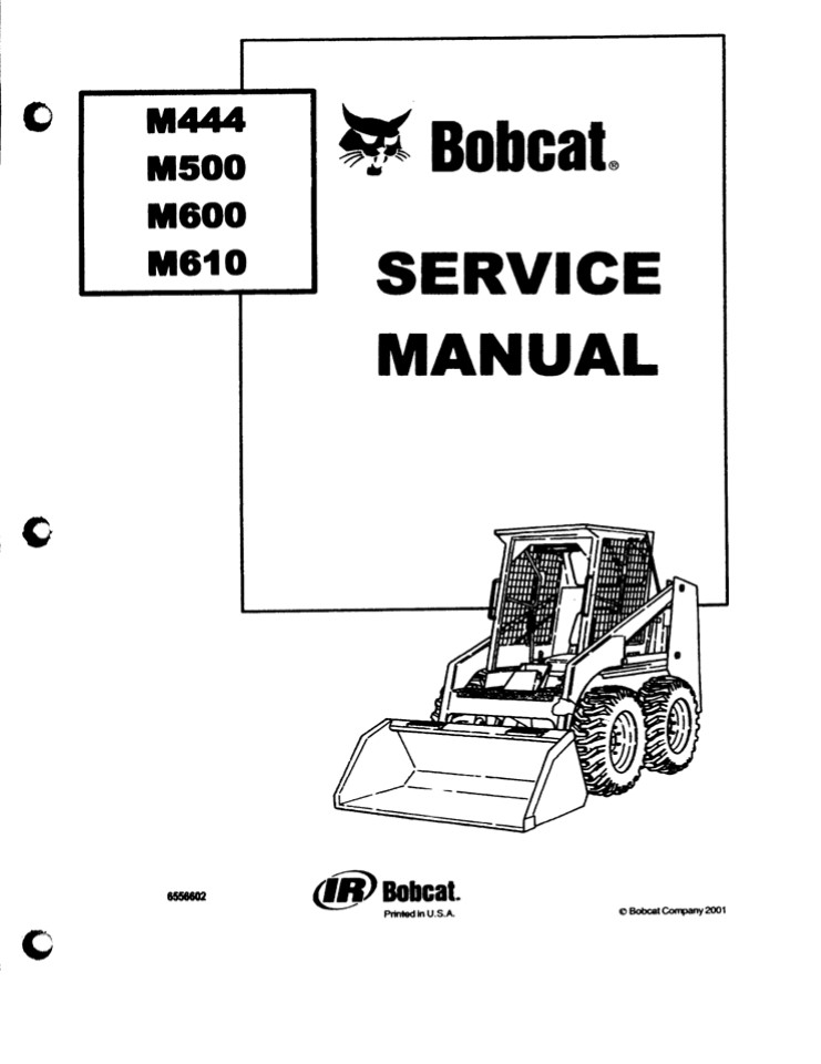
M-444. M-500. M-600 Loaders
6
ROUTINE CLUTCH ADJUSTMENT The Bobcat has two
separate drive trains (one on each side of the
machine), each equipped with two clutches. These
clutches are engaged and disengaged by the
directional control levers. When lever travel
(from neutral) exceeds four inches in either
direction, the clutches need adjustment. This may
occur shortly (about 50 hours) after a new
machine is put into service. After the clutch
facings are seated, lever travel should be
checked every 100 hours and the clutches adjusted
only if lever travel is excessive. On either side
of the machine, the clutch toward the front is
the reverse travel clutch and the clutch toward
the rear is the forward travel clutch. Adjust
according to the following procedure
1.
Shut off the engine before attempting to adjust
the clutches. With the large clutch cap wrench,
remove the protective caps from the four
clutch pins.
2.
- Remove the cotter pins which hold the castle nuts
in place. - With the directional control lever in neutral
position, tighten the front castle nut 1/2 slot.
Move the lever back to check the adjustment.
Repeat this until no more adjustment is needed.
When the handle (hand grip) of the lever can be
moved 3 to 4 inches (maximum) back from neutral
to fu(Iy engaged position, adjustment of the
reverse travel clutch is correct for that side.
You may need to use the small end of the clutch
wrench to make the adjustment (Figure 14).
5.
Tighten the rear castle nut in the same manner,
moving the lever forward to check travel
(maximum) fram neutral, adjustment of the forward
travel clutch is cor- rect for that side.
Fig. 14
Routine Clutch Adjustment
Repeat these adjustments on the other side of the
machine. When you have finished, the levers on
both sides should be in line when they are both
moved forward or back to ? v engaged position.
6.
7. After completing this adjustment, secure each
castle nut with a cotter pin and tighten the
protective caps over the clutch pins with a
clutch cap wrench.
If the quad ring seal sticks to the side panel
when a clutch cap is removed, carefully pull the
quad ring from the panel and place it in its
groove in the cap. Spread a little oil around the
quad ring seal before replacing the cap. I f oil
leakage is noted around the clutch caps, the quad
ring seals must be replaced.
8.
Do not overtighten the clutches. Overtightening
will cause the clutches to be partially engaged
when the control lever is in neutral. This causes
hard starting and clutch wear.
i'
After all four clutch pins have been adjusted and
the protective caps have been installed, sit in
the operators seat and start the engine. With
the directional control levers in neutral, the
machine should stand still. I f the machine
creeps, rocks, or jumps back and forth, the
clutches are Set too tight and must be
readjusted. NOTE If nothing happens when a
directional control lever is moved one way, but
the clutch engages when the lever is moved the
opposite way, (1) there has been a clutch
failure, (2) the needle thrust bearings may be
defective, (3) the clutch actuating thread may be
stripped.
-11-
M-444, M-500, M-600 Loaders
7
CLUTCH REMOVAL AND R EPAI R 2.5 hr. The
directional control clutches are located inside
the gearcases and are actuated by a large square
thread screw mechanism on each clutch. One clutch
on each side of the mach ine is controlled by a
right hand thread nut, the other by a left hand
thread nut. Moving the directional control lever
turns both of the clutch actuating nuts in the
same direction at the same time. Because one is a
right hand thread and the other is a left hand,
they will cause one clutch to engage while the
other clutch moves away from engagement. One of
these clutches controls forward movement of the
wheels on that side of the mach ine the other
clutch controls the reverse movement of the
wheels.
Fig. 15
Remove Thrust Bearings and Races
- Directional control clutch failure is usually
caused by a thrust bearing failure or failure of
the clutch actuating nuts. - The clutch failure may be one of several types
- The clutch actuating nuts may come out of
adjustment if the clutch pins they are mounted
on turn in the gearcase inner sidewall. - The actuating threads and nuts may wear and
become sticky. In some cases a wear pattern in
the actuating nut will cause the clutches to
stick in engaged position. - The actuating nut may wear enough so that it rubs
on the inside gearcase sidewall.
Clutch lining life is quite long and lining
replacement is usually not necessary. The clutch
thrust bearings and the hardened clutch thrust
races that the bearings run between usually fail
prior to clutch lining failure. The hardened
clutch thrust races are ground on both sides and
may be turned over to secure a new wear surface.
The clutch thrust bearings should normally be
replaced when the clutches are removed for
actuating nut service.
F ig. 16
Removing Outside CIutch Plate
- Follow this procedure to remove the clutch and
actuating assembly - Remove the protective clutch caps and the
gearcase cover. - Loosen the clutch drive (outside clutch) chain
idler sprocket and remove the clutch drive chain. - Remove the cotter pins from the castle nuts and
remove the castle nuts.
F ig. 17 Removing Sprocket From Idler
- Remove the large hexagon clutch thrust blocks
(nuts). - Remove the thrust bearings and races. Notice
that each clutch thrust bearing is mounted
between two hardened clutch thrust races (Figure
15).
- Remove the outside clutch plate and lining
(Figure 61. - Remove the sprocket from the intermediate idler
I Figure 17).This is necessary to gain enough
slack in the intermediate (inside clutch) chain
so that the chain can be released from the inside
clutch sprockets. - Remove the inside clutch plates, hardened races
and thrust bearings (Figure 18). - Disconnect the clutch actuating linkage and
centering spring. - Remove the seat and engine cover.
Fig. 18 Removing Inside Clutch Plates
11.
Remove the hvdraulic lines to the clutch pins
(Figure 19).
- Remove the clutch pin holding nuts.
- Remove the clutch pins and actu- ating bar
(Figure 20).
Fig. 9 Removing Hyd. Lines To Clutch Pins
Fig. 20 Removing Clutch Pins Bar
M-444. M-500. M-600 Loaders
-12-
8
To reinstall the clutch pins, proceed as follows
NOTE The sharp edges are purposely lx'oken from
the actuating threads to keep them from lz'eaking
in use and jamming the threads.
1. Assemble the clutch actuating nuts onto the
actuating bar
A. Face the actuating bar as you would if it were
in the machine.
Fig. 21 Actuating Thread
B. Place the right hand threaded actuating nut
into the right clev- is and the left hand
actuating nut into the left clevis.
NITØ THE OOØTROL LEVER HßØD
C. Install the socket head shoulder screws,
being sure that a small spring washer is placed
Into the clevis behind gach actuating nut. Watch
the washer to be sure it doesn't slip off the
shoulder of the socket head screw when the screw
is being tightened. This would cause it to be
flat- tened against the back of the actuating bar
clevis.
TflE REAR ßRßTINt flUT ÂND
TgREAD Sg0ULD AE "FULL
THRAD OOØTAGT AS SHO!NØ.
FULL THREAD COØTAOT
- D. Turn the clutch pins into the actuating nuts.
- Install the assembly into the machine.
- Grasp the right clutch pin in your right hand
and the left clutch pin in your left hand. - Place the assembly in the clutch pin mounting
holes.
NOTE Install a new lead saal over the clutch pin
threads each time.
Fig. 22 Full Thread Contact at Rœr Pin
C. Turn the clutch pin holding nuts (large 7/8
nuts) onto the clutch pins and draw the clutch
pins up until they are just snug in the frame.
FULLTHREAD COØTAOT
NOTE The nuts must be ti_at_t enough so tfse pins
will not turn un- br hand pressure.
D. Connect the actuating bar to the lever
linkage bar.
RlGHT
3. To insure positive clutch engagement the
clutch pins are adjusted at this point.
Move the directional control lever forward so the
hand grip is approximately 4 ahead of its
neutral position (Figure 22).
A.
B. Turn the rear clutch pin so there is full
thread contact between the actuating threads
(Figures 22 and 23).
Fig. Zg Full Threed Contact
-13-
II-444. M-5Œl. M-600 I.oeders
9
- NOTE To turn the clutch pin, turn the castle nut
onto the outside of the clutch pin so the slots
in the nut are toward the machine. Put a pin
through the slots in the nut and the hole in the
pin. Turn the pin with a wrench. - When the rear clutch pin has the right
adjustment, tighten the clutch pin holding nut.
Use a wrench on the castle nut to hold the clutch
pin while you are tightening the holding nut.
This prevents turn1ng the clutch pin. - Mount the inside clutch plates.
- The clutch thrust bearing may fall from the end
of the clutch hub when an inside clutch is being
installed. Put a small amount of grease on the
thrust bearing to hold it on the hub, or hold it
with your fingers as you replace the clutch
plate. Use new thrust bearings. - Align the front clutch plate to the rear clutch
plate with both clutches in neutral position. Lay
a straightedge along the faces of the clutch
plates and turn the front clutch pin until the
clutch plates are in line (Figure 24). Tighten
the holding nut, holding the clutch pin so it
doesn't turn. - Mount the intermediate (inside clutch) chain and
replace the idler sprock et. Tighten the chain. - NOTE The intermediate chain goes over the idler
sprocket, under the sprocket on the front clutch
and over the sprocket on the rear clutch. - Install the clutch linings onto the inside
clutch plates. Make sure the linings fit easily
over the shoulders on the inside clutch plates.
If a lining does not slide easily over tha
shoulder, file or sandpaper the inside diameter
of the lining until it fits loosely on the
shoulder. - If the lining is forced onto the shoulder of the
clutch plate it may crack the center member of
the lining and cause a lining failure after only
a few hours ærviœ. lt must turn freely on the
clutch plate.
- Mount the outside clutch plates.
- Install the hardened thrust races and clutch
thrust bearings on the outside clutch plates. The
hardened race is mounted on the shoulder of the
clutch plate, followed by the thrust bearing. - NOTE Turn the thrust race mounted in the large
hexagon thrust block (nut) and the thrust race on
the clutch plate to the sides that have not been
in con- tact with the thrust bearing. If both
sides have been worn, replace the thrust races.
Install new thrust bearings. - Loosen the self aligning portion of the large
hexagon thrust block (nut) with the handle of a
screwdriver (Figure 25). I f it cannot be
loosened by this method, place it into a vise or
press and loosen it, being careful not to damage
the wearing surface of the hardened race. - lnstall the large hexagon thrust blocks (nuts).
- Install the castle nuts and cotter pins.
11. With a straightedge, check the alignment of
the upper jackshaft sprocket with the outside
clutch sprockets (Figure 261.
Fjg. 26 Check ing Sprocket Alignment
-14-
M-444. M-500. M-600 Loaders
10
- Reinstall the clutch drive (outside clutch)
chain, tightening it hand tight (Figure 27). It
should be tight enough so that it can be
deflected 1/4 under 10 lbs. spring scale tension
IFigure 28). - Install the gearcase cover.
- Check the lever travel and adjust the clutches if
necessary (See Routine Clutch Adjust- - ment).
- Replace the protective clutch caps.
- Replace the hydraulic lines to the clutch pins.
- In most cases you will not be removing the
forward and reverse clutches at the same time. To
remove one of the clutches and its actuating nut,
proceed as follows - Remove the protective clutch caps and the
gearcase cover. - - Loosen the clutch drive (outside clutch) chain
idler sprocket and remove the clutch drive chain.
Fig. 27
Tightening Clutch Drive Chain
- Remove the cotter pin from the castle nut and
remove the castle nut. - Remove the hexagon clutch thrust dock (nut).
5. Remove the thrust bearing and the hardened
thrust race. Notice that the clutch thrust
bearing is mounted between two hardened clutch
thrust races (Figure 15).
Fig. 28
Checking Tension of Clutch Chain
- Remove the outside clutch plate and lining
(Figure 16j. - Loosen the intermediate chain idler. Remove the
sprocket from the intermediate idler (Figure 17).
This is necessary to gain enough slack in the
intermediate (inside clutch) chain so that the
chain can be released from the inside clutch
sprockets. - Remove the inside clutch plate, hardened thrust
race and thrust bearing (Figure 18).
Remove the socket head shoulder screw that
fastens the clutch actuating bar to the actuating
nut. Be careful to save the small spring washer
which is located in the actuating bar clevis
(behind the actuating nut).
NOTE Proper sprocket alignment and chain tension
are necessary for satisfactory chain life.
10. Remove the hydraulic tubeline (Figure
19).and clutch pin holding nut on the inside of
the loader frame.
- J 1. Remove the clutch pin from the frame.
- The clutch actuating nut is mated to the clutch
actuating thread, which is fastened to the clutch
pin with a woodruff key. To change the clutch
actuating nut and thread, tap the assembly off
the clutch pin and replace with a new thread and
nut. - To reinstall a clutch, follow this procedure
- Install the clutch pin, with an actuating thread
and nut on it, into the clutch pin mounting hole.
Use a new lead washer each time. Turn the clutch
holding nut onto the clutch pin and draw the
clutch pin up until it is just snug in the frame. - Fasten the actuating nut to the actuating bar.
Be sure to insert the small spring washer into
the clevis behind the actuating nut. Be sure the
washer doesn't slip off the shoulder of the
socket head shoulder screw when you're tightening
the screw. This would cause it to be flattened
against the back of the actuating bar clevis.
Check for straightness of the actuating bar.
Straighten if necessary. - Remove these parts from the other clutch
assembly - Cotter pin and castle nut.
- Hexagon thrust block (nut), thrust bearing and
race (Figure 15). - Outside clutch plate(Figure 16)and clutch Ïining.
- Inside clutch plate, thrust race and bearing
(Figure 18).
M-444, M-500, M-600 Loaders
-15-
11
- E. Loosen the hydraulic tubeline at the clutch
pin holding nut end. Loosen the clutch pin
holding nut slightly (this nut is located inside
the loader frame). - To insure positive clutch engagement the clutch
pins are adjusted at this point - Move the directional control lever forward so the
hand grip is approximately 4 ahead of its
neutral position (Figure 22). - Turn the rear clutch pin so there is full thread
contact between the actuating nut and actuating
thread (Figures 22 and 23). - NOTE To turn the clutch pin, turn the castle nut
onto the outside of the clutch pin so the slots
in the nut are toward the machine. Put a pin
through the slou in the nut and the hole in the
pin. Turn the pin with a wrench. - When the rear clutch pin has the right
adjustment, tighten the clutch pin holding nut.
Use a wrench on the castle nut to hold the clutch
pin while you are tightening it. - Mount the inside clutch plates.
- The clutch thrust bearing may fall from the end
of the clutch shoulder when an inside clutch is
being installed. Put a small amount of grease on
the thrust bearing to hold it on the shoulder, or
hold it with Y fingers as you replace the
clutch plate. Use a new thrust bearing. Turn the
hardened thrust races so an unworn side comes in
contact with the new thrust bearing. - Align the front clutch plate to the rear clutch
plate with both clutches in neutral position. Lay
a straightedge along the faces of the clutch
plates and turn the front clutch pin until the
clutch plates are in line (Figure 24). Tighten
the clutch pin holding nut, holding the castle
nut with a wrench to keep the clutch pin from
turning. - Mount the intermediate (inside clutch) chain and
replace the idler sprocket. Tighten the dhain. - NOTE The intermediate chain goes over the idler
sprocket, under the sprocket on the front clutch
and over the sprocket on the rear clutch. - Install the clutch linings onto the inside
clutch plates. Make sure the linings fit easily
over the shoulders on the inside clutch plates.
If a lining does not slide easily over the
shoulder, file or sandpaper the inside diameter
of the lining until it fits properlv - If the lining is forced onto the dioulder of the
clutch plate it may crack the center member of
the lining and cause a lining failure after only
a few hours service. If must turn freely on the
clutch plate. - Mount the outside clutch plates.
M-444, M-500, M-600 Loaders
-16-
12
9. Loosen the self aligning ponion of the large
hexagon thrust block (nut) with the handle of a
screwdriver (Figure 25). I f it cannot be
loosened by this method, place it into a vise or
press and loosen it, (being careful not to damage
the wearing surface of the hardened race) or
replace it with a new assembly.
NOTE COrIect sprocket alignment is nec- essary
for satisfactory chain life.
- Install the large hexagon thrust blocks (nuts).
- Install the castle nuts and cotter pins.
- With the directional control lever in neutral,
check the alignment of 1he upper jack- shaft
sprocket with the rear outside clutch sprockets
(Figure 26). - NOTE On the left side of the machine (with
tapered jackshaft) align the belt, then shim the
upper jackshaft sprocket for aIigr\ment. Refer to
page t2. - Reinstall the clutch drive (outside clutch)
chain, tightening it hand tight (Figure 27). It
should be tight enough so that it can be
deflected 1/4 under 10 lbs. spring scale tension
(Figure 28). - Be sure the intermediate chain has been tightened
(Figure 29). It should require 15 lbs. spring
scale tension to deflect it 1/4 (Figure 30). - Install the gearcase cover. Check the condition
of the gasket.
15. Check the lever travel and adjust the
clutches if necessary (See Routine Clutch
Adjustment).
Fig. 29
Tightening Intermediate Chain
16. Replace the protective clutch caps. Check the
condition of the quad ring seals.
17. Replace the hydraulic lines to the clutch
pins. REPLACING CLUTCH NEEDLE BEARINGS When
replacing clutch needle bearings, press one
bearing in from each side of the clutch plate.
The bearings should be pressed in so they are
flush with the outside of the hub I Figure
31). NOTE If the chains are too tint, both
bearings will work inward toward the center of
the hub. VARIABLE SPEED DRIVE The variable speed
drive mechanism on every Bobcat is factory
adjusted, but it may, in time, require further
adjustment. Several conditions can cause loss of
power through the variable speed drive belt. They
are listed below with their remedies
Fig. 30
Checking Tension of Chain
- If the belt is bottoming and slipping in the
drive (engine) sheave, the operator should nudge
the variable speed lever slightly toward higher
speed. This will bring the sides of the sheave
in to where they can grip the belt. - NOTE 60ost bait bottoming and slipping can be
avoided. Whenever tha operator places the
variabla speed in low speed position, he should
nudga the lever forward to move the belt slightly
ouMard from the hub. - If the belt slips and is not bottoming, tighten
it by turning the three nuts on the spring loaded
jackshaft sheave. Tighten these nuts evenly, one
turn at a time. Aftr tightening each nut one
turn, start the machine and check for slippage.
I f the belt continues to slip, it may be worn
too narrow to be gripped by the drive sheave, in
which case it should be replaced with a new belt.
The spring loaded jack- shaft sheave must be
readjusted after replacing the belt. A new belt
is 1-13/16 wide at the top. When a new belt is
installed adjust the three nuts on the spring
loaded jackshaft sheave so 1/4 inch of thread
shows past the three nuts.
3.
jjg. g
Replacing Clutch Needle Bearings
Do not overtighten the spring-loaded jackshaft
sheave because this will cause the belt to wear
excessively.
-17-
M-444, M-500, M-600 Loaders
13
DRIVE BELT REPLACEMENT (Split Jackshah) 1.5
hr. On machines with a split jackshaft use the
following procedure 1. Remove the outside
portion of the engine variable width sheave and
hydraulic cylinder assembly, located at the left
rear of the machine, on the engine output shaft
(Figure 32). Clean the cylinder and hose before
disconnecting the fitting. Plug the cylinder port
and hose to keep out dirt. NOTE Obœrve whether
there are any spaœrs beMeen the variable speed
cylinder
mounting bracket and the frame bracketc Thèse
spacers must be replaced as they were (M-600 and
M-500 gasoline and LP gas).
Fig. 32
Removing Engine Sheave Half
- On machines with a swivel œupling, remove the
swivel, then remove the large holding nut to
separate the sheave halves (M-600 and M-500
dieœl, M-600 and M-500 electric, M-444 gasoline
and LP gas). - Remove the split jackshaft connector (Figure
33). The connector must be replaced in the same
position as it was before removal. Matched ends
are punch marked. Keep the marked ends of the
block toward the sheave. - Pass the worn belt between the shah ends and
replace it with a new belt.
4. Reinstall the split jackshaft connector,
exactly as it was before. Four screw heads should
be up and four down. Retorque the eight connector
screws to 18-20 ft. lbs. torque. The screws must
be tightened down evenly.
Fig. 33
Removing Jackshaft Connector
- Pull the belt with a pry bar to force it into the
driven sheave (Figure 34j. This will make it
possible to replace the outside (engine) sheave
half. Do not use a flat bar, as it will damage
the belt. - NOTE The spring loaded variable width Sheave
will have to be rwdjustwl altar - a naw belt is installecl because a new belt is
wider than an old, worn beIc - Reinstall the outside drive sheave half and
reconnect the hydraulic hose. Align the balance
marks on the sheave halves when reinstalling.
F ig. 34
Pulling Belt into Driven Sheave
7. Check the belt alignment of the drive and
driven sheaves (Figure 35). DR IVE BELT
REPLACEMENT (One Piece Jackshaft) 5 hr.) On
machines with a one piece jackshaft, use the
following procedure
WITII BEIN AT HAL YA8IABLE LsÏ A 5TIIAItîITDE
ALOIIt
1. Remove the outside portion of the engine
variable width sheave and hydraulic cylinder
assembly, located at the left rear of the
machine, on the engine output shaft (Figure 32).
Clean the cylinder and hose before disconnecting
the fitting. Plug the cylinder port and hose to
keep out dirt.
Observe whethw there are any apaosre beMasn the
varbbl0 zpsad oyllnder mounting.bracket and the
frame brackets. These spsoa'e must be replaoad as
they were (11-600 gaaollne and LP gr). On
machines with a swivel coupling, remove tha
swivel, then remove the large holding nut to
.separate the chewe halves (M600 dlxl, M600 and
M600 electric, M-444 gasoline and LP gas).
NOTE
R.1027
Fig. 35
chelng Belt Allgnrrant
- Remova the protective clutch caps from both sides
of the machine. - Remove both gearcase covers.
- Loosen the clutch drive (outside clutch) chain
tighteners and remove the cIutch drlva chains. - Remove the sprocket retaining screws end the
sprockets from both ends of tha jack shaft.
M444, M600, M600 Loaden
18-
14
- NOTE You may need to use a puller to remove the
sprocket from the end of the shaft. Remove the
sprocket retaining screw from the jackshaft and
remove the retaining washers. Turn the screw back
into the end of the shaft (Figure 36). - Loosen the set screws in the hub of the
stationary half of the driven sheave. - Drive the driven sheave assembly toward the
right far enough so the square key can be removed
from the jackshaft.
- Remove the square key and move the sheave
assembly back toward the left. - Remove the bearing lock ing collar from each end
of the jackshaft. Loosen the set screw in the
bearing locking collar (Figure 37) and rotate the
collar opposite the shaft rotation until it is
loose on the bearing (Figure 38). Rotating it
about 3/4 will unlock it. Rotating it too far
will relock it (backward).
Fig. 36
Pulling Upper Jack shaft Sprocket
- Thoroughly clean that portion of the right end
of the jackshaft which will be driven through the
right bear g. - Drive the jackshaft to the right (through the
sheave) far enough to pass the belt between the
jackshaft and the machine sidewall. - Remove the worn belt and replace it with a new
one. - To reassemble, align the jackshaft sprocket with
the outside clutch sprockets on the right side
of the machine. When they are aligned, lock the
bearing locking collar onto the bearing hub by
rotating it in the direction of shaft rotation
(Figure 39). - Tighten the locking collar set screw (Figure 37).
- Mount the sprocket on the leh end of the
jackshaft and align it to the outer clutch
sprockets. Use shim washers if necessary. Lock
the locking collar by turning it in the
direction of shah rotation. Tighten the locking
collar set screw (Figure 37). - NOTE The spring loaded driven sheave will have
to be readjusted after a new belt is installed a
new belt is wider than an old, worn belt. - 15 Reinsert the key and set screws in the driven
sheave hub. Check the alignment - of the drive and driven sheaves (Figure 35). Move
the driven sheave on the jackshaft - to align. Tighten the set screws.
Fig. 37
Loosening Set Screw
G
Fig. gg
Removing Bearing Locking Collar
DRIVEN SHEAVE REMOVAL (Split Jackshaft) 3
hr.j To remove a driven (spring loaded) sheave,
proceed as follows 1. Remove the outside
portion of the engine variable width sheave and
hydraulic cylinder assembly, located at the left
rear of the machine, on the engine output shaft
(Figure 32). Clean the cylinder and hose before
disconnecting the fitting. Plug the cylinder port
and hose to keep out dirt. NOTE Observe whether
there are any spacers beMeen the variable speed
cylinder mounting bracket and the frame bracket.
These spacers must be replaced as they were
(M-500 Kohler M-600 Wisconsin).
Fig. 3g
Reinstalling Bearing Lock ing Collar
- On machines with a swivel coupling, remove the
swivel, then remove the large holding nut to
separate the sheave halves. - Remove the protective clutch caps from the left
gearcase cover. - Remove the gearcase cover.
- Loosen the clutch drive (outside clutch) chain
tightener and remove the clutch drive chain. - Remove the sprocket retaining screw and the
sprocket from the end of the jack- shaft.
NOTE You may need to use a puller to remove the
sprocket from the end of the shaft. Remove the
sprocket retaining screw from the jackshaft and
remove the retaining washers. Turn the screwback
into the end of the jackshaft (Figure 36).
Fig. 40
Checking Sprocket Alignment
M-444, M-500, M-600 LoaJers
-19-
15
6. Remove the bearing locking collar from the
jackshaft. Loosen the set screw in the bearing
locking collar (Figure 371 and rotate the collar
opposite the shaft rotation until it is loose on
the bearing (Figure 38). Rotating it 3/4 will
unlock it. Rotating it too far will relock it
(backward).
7. Remove the split jackshaft connector (Figure
41). The connector must be replaced in the same
position as it was before removal.
8. Drive the jackshaft half toward the center of
the machine with a rubber or plastic mallet
(Figure 42).
9. Pull the assembly into the opening in front
of the engine and remove it by pulling it
straight up on all machines except the M-500
gasoline and LP gas (Figure 43). On these models
(M-500 gasoline and LP gas) take the assembly out
through the bottom of the machine.
Fig. 41
Removing Split Jack shaft
- These parts must be removed from the machine to
make removal of the jackshaft and sheave assembly
possible. - On M-600 gasoline and LP gas machines, remove the
following - The hydraulic tubeline from the clutch
lubrication manifold to the left rear clutch pin. - Disconnect and remove the battery.
Fig. 42
Driving Jack shatt Half
c. Remove the hydraulic lines from the variable
speed control valve to the check (lock) valve. If
the machine is not equipped with a check valve,
re- move the hydraulic line from the variable
speed control valve to the variable speed
cylinder hose.
- On M-600 and M-500 diesel machines, remove the
following - The hydraulic tubeline from the clutch
lubrication manifold to the left rear clutch pin.
b. Remove the hydraulic lines from the variable
speed control valve to the check (lock) valve. If
the machine is not equipped with a check valve,
re- move the hydraulic line from the variable
speed control valve to the variable speed
cylinder hose.
Fig. 43
Inserting Driven Sheave Assembly
- To reinstal I a driven (spring loaded) sheave,
proceed as follows (Split Jack shaft) - Insert the assembly (spring loaded sheave and
jackshaft half) into the machine (Figure 43). - Install a variable speed belt over the jackshaH.
- Reinstall the split jackshaft connector, matched
ends together (Figure 41). Four screw heads
should be up and four down. Tighten the screws
down evenly.
4. Pull the belt into the driven sheave with a
pry bar (Figure 44). This will make it possible
to replace the outside (engine) sheave half. Do
not use a flat bar, as this will damage the belt.
Fig. 44
PulIing Belt Into Driven Sheave
5. Reinstall the outside drive sheave half and
reconnect the hydraulic hose. Align the balance
marks on the sheave halves when reinstalling.
WITII BELT AT HAIR ARIA8II LkY A ST4AlgHTEBgE
AL0?IG THE ORIYEIJ SNEgE AS SNOWG
6. Mount the sprocket on the end of the
jackshaft. Align the sprocket with the outside
clutch sprockets (Figure 40).
7. Lock the bearing lock ing collar on the
bearing hub by turning it in the direction of
shaft rotation (Figure 39).
IluEnSlsNS m z
SHs0I.r BE THE SAr
8. Tighten the lock ing collar set screw (Figure
37) .
9. Reinstall the clutch drive chain. Tighten the
chain hand tight (Figure 46). You should be able
to deflect the chain 1/4 using 10 lbs. of spring
scale tension (Figure 47).
PI-\ 056
Fig. 45
Check ing Belt Alignment
10. Reinstall the gearcase cover and protective
clutch caps.
-20-
M-444, M-500, M-600 Loaders
16
- Reinstall the split jackshaft connector and
tighten the screws down evenly to 120 ft. lbs. - Check the belt alignment of the drive and driven
sheaves (Figure 45). If the belt is not properly
aligned, do this - Start the engine and move the variable speed belt
to half variable position.
Stop the engine. B. Loosen the set screws on the
hub of the stationary half of the sheave. Move
the sheave sideways on the jackshaft until proper
alignment is achieved.
F ig. 46
Tightening Clutch Drive Chain
- ORIVEN SHEAVE DISASSEMBLY (.5 hr.
- To disassemble the driven sheave assembly after
it has been removed from the machine, follow this
procedure (tapered split jackshaft) - Remove the grease fitting.
- Remove the three spring retaining nuts.
- Remove the spring.
- Remove the movable half of the sheave from the
shaft. - Remove the sheave retaining nut. A special
wrench is available for this. - Remove the sheave half by tapping the end of the
shaft on a bloc1 of wood (Figure 48).
PI-1140
Fig. 47
Checking Clutch Orive Chain
To reassemble the sheave onto the tapered split
jackshaft 1. Tap the shaft into the tapered
bore on the fixed half of the sheave (Figure 49).
Be sure the key is being included in the assembly.
2 Mount the retaining nut. Tighten the nut to 130
ft. lbs. torque. Use a spanner wrench or a punch
and hammer. 3. Check the movable half of the
sheave to determine the condition of the grease
seals. Replace the seals if they have been
allowing grease to pass. I?eplace the bushings if
they are worn and allowing the movable half of
the sheave to vibrate or wobble on the shaft.
Fig. 48
Removing Sheave Half From Shaft
- Mount the movable half of the sheave on the
shaft. - Mount the spring.
- Loosen the nut on one of the guide bolts and
slide the bolt through far enough so a spring
retaining nut can be started (Figure 50). - Retighten the nut on the guide bolt to its former
position. - Start the other spring retaining nuts and tighten
them until they are flush with the ends of the
guide bolts.
F ig. 49
Driving Shaft Into Sheave
- 9. Insert the grease fitting (Figure 51).
- To disassemble the driven sheave assembly after
it has been removed from the machine, follow this
procedure (all except tapered jackshaft units) - Remove the grease fitting.
- Remove the three spring retaining nuu.
- Remove the spring.
- Separate the sheave halves. To reassemble
Flg. 50
Mounting Spring Retaining Plate
1. Check the movable half of the sheave to
determine the condition of the grease seals.
Replace the seals if they have been allowing
grease to pass. Replace the bushings if
M-444, M-500, M-600 Loaders
-21-
17
they are worn and allowing the movable half of
the sheav0 to vibrate or wobble on the shaft.
TgRII 7HE THE PI-1157
2. Mount the movable half of the sheave over the
guide bolts.
3. Mount the spring.
4. Loosen the nut on one of the guide bolts and
slide the bolt through far enough so a spring
retaining nut can be started (Figure 50).
- Retighten the nut on the guide bolt to its former
position. - Start the other spring retaining nuts and tighten
them until they are flush with the ends of the
guide bolts. - Insert the grease fitting (Figure 51). The grease
fitting must be slotted relief type to prevent
overgreasing and seal damage. - NOTE Not all tapered jackshaft halves are the
same. See Figure 52 for dimensional - differences and models used on.
Fig. 51 Insen The Grease Fitting
A MODE1 PART NO. Al103 A
M-500G M-600D M-500D 6503352 3-7/8
M-600G M-600E 6503348 4-1/4
M-500E 6503379 4
DRIVEN SHEAVE ALIGNMENT (Belt Alignment)
1. Check to be sure the fixed half of the sheave
is tight on the jackshaft, and has not moved
sideways on the shaft, causing belt misalignment.
This can be checked by laying a straightedge
along the driven sheave with the belt at half
variable position. The belt should be parallel to
the straightedge along its entire length (Figure
45). , 2. Check the condition of the movable
half of the sheave to see that it slides freely
on the shaft. It may have to be cleaned and
relubricated, and new grease seals installed. 3.
Check the condition of the three sliding studs
(guide bolts) and related oilite bearings to be
sure excessive wear has not caused wobbly motion
(or vibration) of the two sheave halves and belt
breakage.
FÏg. 52
Split Tapered Jackshaft
- If the variable speed belt is not properly
aligned it will be necessary to move the driven
sheave sideways until it is. On machines with
tapered split jackshaft, do this - Remove the left gearcase cover.
- Loosen the split jackshaft connector.
- Remove the clutch drive (outside clutch) chain.
- Remove the sprocket retaining screw and the
sprocket from the end of the jackshaft.
Fig. 53
Rerriove Upper JckshaftSprocket
NOTE You may need to use a puller to remove the
sprocket from the end of the shaft. Remova the
sprocket retaining screw from the jackshaft and
remove the retaining washers Turn the screw back
into the end of the jackshah (Figure 53). 5.
Remove the bearing locking collar set screw
(Figure 37) and the bearing locking collar
tFigure 54) from the jackshaft. Loosen the
bearing locking collar by turning it opposite the
direction of shaft rotation.
6. Slide the jackshaft half to the desired
position and tighten the 8 connector screws.
Tighten the screws evenly to 18-20 ft. lbs.
torque.
Ftg.
Rernoving Bearing Lock ing Collar
- Recheck the alignment (Figure 45).
- Reinstall and tighten the bearing locking collar
on the bearing hub. To tighten it, turn it in the
direction of rotation (Figure 55). - Mount the jackshaft sprocket. Use spacer washers
to align the sprocket with the outside clutch
sprocket. Check the alignment (Figure 40).
Install the sprocket retaining washer and screw. - Reinstall the clutch drive chairj. Tighten the
chain hand tight (Figure 46). You should be able
to deflect the chain 1/4" using 10 lbs. of spring
scale tension (Figure 471.
Fig. 55
Reinstalling Bearing Lock ing Collar
IN. Reinstall the gearcase cover and the
protective clutch caps. M-444, M-500, M-600
Loaders
18
On machines without a tapered split jackshaft it
is not necessary to remove the gearcase cover and
jackshaft sprocket when aligning the belt.
Proceed as follows
WITII BELT AT NALF YA8IABL LOT A STgAItIITEIÏgE
A10Ng TXE ggIYEN SIIEkYE AS SHOWII
1. Loosen the Mo set screws which hold the
driven sheave to the shaft. They are located on
the hub of the stationary half of the sheave
(between the sheave assembly and the machine
sidewall).
- Slide or di'ive the sheave in the direction
needed to give proper belt alignment. - Recheck the alignment (Figure 56).
ê I SN0LS B
E SAgE
4. Tighten the two set screws securely. UPPER
JACKSHAFT BEARING REPLACEMENT Remove and replace
an upper jackshaft bearing as follows
1.5 hr.
PI-1056
Fig. Ü6
Check ing Belt Alignment
- Remove the protective clutch caps and the
gearcase cover. - Remove the clutch drive (outside clutch) chain.
- Remove the sprocket retaining screw and the
sprocket from the end of the jackshaft. NOTE You
may need to use a puller to remove the sprocket
from the end of the shah. Remove the sprocket
retaining screw from the jackshaft and remove - the retaining washers Turn the screw back into
the end of the jackshaft (Figure 53). - Remove the bearing locking collar set screws
(Figure 37) and the bearing locking
collar (Figure 54). from the jackshaft. Loosen
the bearing locking collar by turning it opposite
the direction of shaft rotation. 5. Remove the
four nuts which hold the bearing housing to the
gearcase sidewall and pull the bearing and
housing from the shaft.
Fig. 57.
Removing Bearing from Housing
6. Insert a length of shaft material (same
diameter as the jackshaft) into the bearing and
pull on the'shaft until the bearing becomes free
of the housing IFigure 57). To reinstall
- Place a new bearing vertically into the housing.
You should be able to turn it freely in the
housing (Figure 58). If you can't, replace the
housing with a new one. - With a length of shaft material inserted into
the bearing, rotate it into the housing (Figure
57). It should not take over 200 in. lbs. force
to rotate the bearing into the housing.
Fig. 58
Check ing Housing Tolerance
NOTE The offset hub of the bearing must be
toward the flanged side of the housing (not at
the flat mounting side). 3. When mounting the
housing to the gearcase inner sidewall, use new
sealing washers behind the nuts to prevent oil
leakage. ENGINE VARIABLE DRIVE SHEAVE REMOVAL .ï
Use the following procedure to pull an engine
variable drive sheave (M-600D, M-500D M-600G)
Fig. 59
Removing Holding Screw Washer
- Remove the holding screw and machined holding
washer (Figure 59). - Remove the washer from the holding screw and
replace the screw in the end of the crankshaft.
Turn it in until the head of the screw bottoms
against the crankshaft. - Insert 1/4 cap screws into the tapped holes in
the fixed sheave hub. - Mount a puller on the sheave half (Figure 60)
behind the cap screws.
Do not substitute a common flat washer for the
machined holding waher when reassembling the
vari- able drive sheave to the engine shaft.
l '
Fig. 60
Mount Puller on Sheave Helf
M-444, M-500, M-600 Loaders "
19
MORE MANUALS https//www.ebooklibonline.com/
Suggest If the above button click is invalid.
Please download this document first, and then
click the above link to download the complete
manual. Thank you so much for reading
20
5. Pull the sheave half from the engine shaft
(Figure 61).
- Use the following procedure to pull an engine
variable drive sheave (M-500G, M-444, M-600E
M-500E). - Loosen the two set Screws in the stationary
sheave half. - Install a bearing puller lFigure 60) , tightening
the puller firmly behind the keys. - Pull the sheave half from the engine shah l
Figure 61). - DRIVE SHEAVE MODI FICATION (M-444, M-600D,
M-500D, M-600E - M-500El 2 hr.
- Replacing the roll pins in these sheave half
assemblies with set screws will prevent possible
sheave damage due to roll pins working out of
place. To modify, follow these steps
Fig. 61
Pulling Sheave Half from Shaft
5/8 7/8 A1l01
1.. Press the cylinder barrel into the sheave
half as far as it will go. Use a long bolt with
large washers on each end to hold it in place.
2. Locateand dritt a 19/64 hole (Figure 621.
- Insert a 5/16 x 1/2 long roll pin into the
hole. This will assure alignment when drilling
future holes. - Using the pilot holes in the sheave half, drill
three 15/16 holes through the cylinder barrel. - Tap the holes 3/8 NC, but only to within 1/16
of cylinder barrel inner surface. - NOTE It is important that the set screws bottom
out in the threads of the cylinder barrel.
Use Loc-Tite on the screws to keep them securely
in place.
Fig. 62 Location of Alignment Hole
6. When assembling the sheave halves be sure to
align the arrow on the movable half to the chisel
mark on the fixed half. AXLE REMOVAL IRemove and
Replace 2.5 hr. (front) 3.5 hr. (rear) j To
remove an axle from the Bobcat loader (front
axle) 1. Drain the oil from the gearcase.
2. Raise the side of the machine that the axlé
will be removed from.
Fig. 63
Rerroving Geared qyg
- Disconnect the linkage from the foot pedals.
- Remove the floor panels.
- Remove the wheel from the ax)e that is to be
removed.
Fig. 64
Loosen the Intermediate Chain
Fig. 66
Loosen the Final Drive Chains
6. Remove the gearcase cover (Fig ure 63).
- Loosen the intermediate (inside clutch) chain
(Figure 64). - Loosen the final drive chains (Fig- ures 65 and
66).
9. Remove the oil cap at the end of the axle
(Figure 67) .
Fig. 6s
Loosen the Final Drive Chains
Fig. 67
Reroving Oil Cap end of Axle
xa xa nJ Ann en.Ann
21
https//www.ebooklibonline.com Hello dear
friend! Thank you very much for reading. Enter
the link into your browser. The full manual is
available for immediate download. https//www.ebo
oklibonline.com
Recommended
CrystalGraphics Presentations


