

New Holland TV145 Tractor Service Repair Manual Instant Download PowerPoint PPT Presentation
Title: New Holland TV145 Tractor Service Repair Manual Instant Download
1
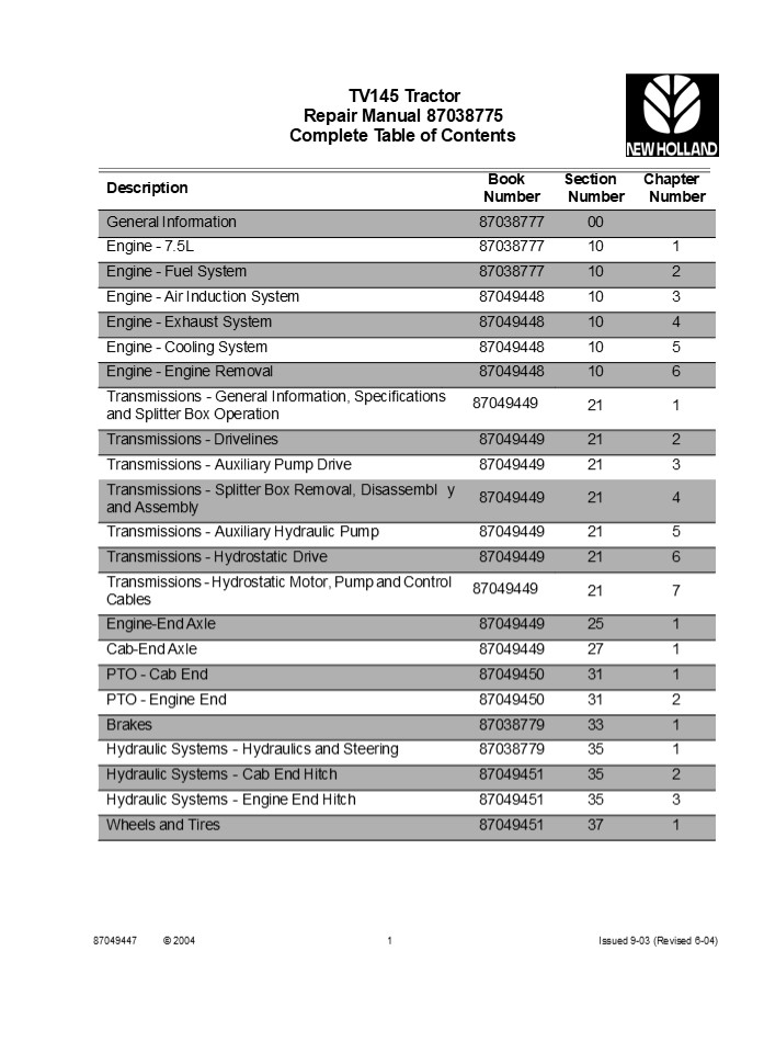
TV145 Tractor Repair Manual 87038775 Complete
Table of Contents
Book
Section
Chapter
Description
Number Number Number
General Information 87038777 00
Engine - 7.5L 87038777 10 1
Engine - Fuel System 87038777 10 2
Engine - Air Induction System 87049448 10 3
Engine - Exhaust System 87049448 10 4
Engine - Cooling System 87049448 10 5
Engine - Engine Removal 87049448 10 6
Transmissions - General Information, Specifications 87049449 Transmissions - General Information, Specifications 87049449 21 1
Transmissions - Drivelines 87049449 21 2
Transmissions - Auxiliary Pump Drive 87049449 21 3
Transmissions - Splitter Box Removal, Disassembl and Assembly y 87049449 21 4
Transmissions - Auxiliary Hydraulic Pump 87049449 21 5
Transmissions - Hydrostatic Drive 87049449 21 6
Transmissions - Hydrostatic Motor, Pump and Control 87049449 Transmissions - Hydrostatic Motor, Pump and Control 87049449 21 7
Engine-End Axle 87049449 25 1
Cab-End Axle 87049449 27 1
PTO - Cab End 87049450 31 1
PTO - Engine End 87049450 31 2
Brakes 87038779 33 1
Hydraulic Systems - Hydraulics and Steering 87038779 35 1
Hydraulic Systems - Cab End Hitch 87049451 35 2
Hydraulic Systems - Engine End Hitch 87049451 35 3
Wheels and Tires 87049451 37 1
and Splitter Box Operation
Cables
87049447
2004
1
Issued 9-03 (Revised 6-04)
2
TV145 Tractor
Book
Section
Chapter
Description
Number Number Number
Ballasting 87049451 37 2
Frames 87049451 39 1
Climate Control 87038780 50 1
Electrical System 87038780 55 1
Accessories 87038781 88 1
Cab - General Information 87038781 90 1
Cab - Removal and Installation 87038781 90 2
Cab - Exterior 87038781 90 3
Cab - Interior 87038781 90 4
Cab - Control Consoles 87038781 90 5
87049447
2
Issued 9-03 (Revised 6-04)
3
TV145 Tractor Repair Manual Table of Contents
Section
Chapter
Description
Number Number
General Information 00
Engine - 7.5L 10 1
Engine - Fuel System 10 2
87038777
2003
1
Issued 9-03
4
https//www.ebooklibonline.com Hello dear
friend! Thank you very much for reading. Enter
the link into your browser. The full manual is
available for immediate download. https//www.eb
ooklibonline.com
5
SECTION 00 GENERAL INFORMATION SECTION 00 -
GENERAL INFORMATION CONTENTS
Section 00 000
Description Page Precautionary Statements . . . .
. . . . . . . . . . . . . . . . . . . . . . . . .
. . . . . . . . . . . . . . . . . . . . . . . . .
. . 3 Safety Precautions . . . . . . . . . . . .
. . . . . . . . . . . . . . . . . . . . . . . . .
. . . . . . . . . . . . . . . . . . . . . . . . .
3 General Considerations . . . . . . . . . . . .
. . . . . . . . . . . . . . . . . . . . . . . . .
. . . . . . . . . . . . . . . . . . . . .
5 Tractor Identification . . . . . . . . . . . .
. . . . . . . . . . . . . . . . . . . . . . . . .
. . . . . . . . . . . . . . . . . . . . .
12 Engine Identification . . . . . . . . . . . .
. . . . . . . . . . . . . . . . . . . . . . . . .
. . . . . . . . . . . . . . . . . . . . . .
15 Service Techniques . . . . . . . . . . . . . .
. . . . . . . . . . . . . . . . . . . . . . . . .
. . . . . . . . . . . . . . . . . . . .
17 Minimum Hardware Tightening Torques . . . . .
. . . . . . . . . . . . . . . . . . . . . . . . .
. . . . . . . . . . . . 18 Standard Torque Data .
. . . . . . . . . . . . . . . . . . . . . . . . .
. . . . . . . . . . . . . . . . . . . . . . . . .
. . . . . . 20 Recommended Lubricants and
Coolants . . . . . . . . . . . . . . . . . . . .
. . . . . . . . . . . . . . . . . . . . .
22 Recommended Sealants . . . . . . . . . . . . .
. . . . . . . . . . . . . . . . . . . . . . . . .
. . . . . . . . . . . . . . . . . 24
6
SECTION 00 GENERAL INFORMATION
FOREWORD Appropriate service methods and correct
repair procedures are essential for the safe,
reliable operation of all equipment, as well as
the personal safety of the individual performing
the repair.
All data and illustrations in this manual are
subject to variations in build specification.
This information was correct at the time of
issue, but New Holland policy is one of
continuous improvement, and, the right to change
specifications, equipment, or design at any
time, without notice, is reserved.
This Repair Manual provides troubleshooting,
overhaul, and pressure-testing instructions using
recommended procedures and equipment. Follow-
ing these instructions will ensure the safe,
efficient, and timely completion of the service
or repair. There are numerous variations in
procedures, techniques, tools, and parts for
servicing machines, as well as in the skill of
the individual doing the work. This manual
cannot possibly anticipate all such variations
and provide advice or cautions as to each.
Accordingly, anyone who departs from the instruc-
tions provided in this manual must first
establish that their personal safety, the safety
of others, and the integrity of the machine will
not be compromised by the choice of methods,
tools or parts. The manual is divided into
sections which are subdivided into chapters
Each chapter contains information on general
operating principles, detailed inspection,
overhaul and, where applicable, specific
troubleshooting, special tools, and
specifications.
ABOUT IMPROVEMENTS New Holland is continually
striving to improve its products. We must,
therefore, reserve the right to make
improvements or changes when it becomes
practical and possible to do so, without
incurring any obligation to make changes or
additions to the equipment sold previously.
ALL SPECIFICATIONS ARE SUBJECT TO CHANGE WITHOUT
NOTICE.
PART AND ACCESSORIES Genuine NEW HOLLAND parts
and accessories have been specifically designed
for NEW HOLLAND MACHINES.
We would like to point out that NON GENUINE
parts and accessories have not been examined and
released by NEW HOLLAND. The installation and or
use of such products could have a negative
effect upon the design characteristics of your
machine and thereby affect its safety. NEW
HOLLAND is not liable for any damage caused by
the use of NON GENUINE NEW HOLLAND parts and
accessories.
Any reference in this manual to right, left,
rear, front, top, or bottom is as viewed from
the operators seat, looking toward the engine.
7
SECTION 00 GENERAL INFORMATION
SAFETY PRECAUTIONS Practically all service work
involves the need to drive the tractor. The
operators manual, supplied with each tractor,
contains detailed safety precautions relating to
driving, operating, and servicing that tractor.
These precautions are as applicable to the
service technician as they are to the operator
and should be read, understood and practiced by
all personnel. Prior to undertaking any
maintenance, repair, overhaul, dismantling or
reassembly operations, whether within a workshop
facility or in the field, consideration should
be given to factors that may have an effect upon
safety, not only upon the mechanic carrying out
the work, but also upon bystanders.
PRECAUTIONARY STATEMENTS PERSONAL
SAFETY Throughout this manual and on machine
decals, you will find precautionary statements
(DANGER, WARNING, and CAUTION) followed by
specific instructions. These precautions are
intended for the personal safety of you and
those working with you. Please take the time to
read them.
DANGER
This word DANGER indicates an immediate
hazardous situation that, if not avoided, will
result in death or serious injury. The color
associated with Danger is RED.
PERSONAL CONSIDERATIONS The wrong clothes or
carelessness in dress can cause accidents. Check
to see that you are suitable clothed. Some jobs
require special protective equipment.
WARNING
This word WARNING indicates a potentially
hazardous situation that, if not avoided, could
result in death or serious injury. The color
associated with Warning is ORANGE.
CAUTION
Skin Protection Used motor oil may cause skin
cancer. Follow work practices that minimize the
amount of skin exposed and length of time used
oil stays on your skin.
This word CAUTION indicates a potentially
hazardous situation that, if not avoided, may
result in minor or moderate injury. It may also
used to alert against unsafe practices. The color
associated with Caution is YELLOW.
Eye Protection The smallest eye injury may cause
loss of vision. Injury can be avoided by wearing
eye protection when engaged in chiselling,
grinding, discing, welding, and painting.
FAILURE TO FOLLOW THE DANGER, WARNING, AND
CAUTION INSTRUCTIONS MAY RESULT IN SERIOUS
BODILY INJURY OR DEATH.
Breathing Protection Fumes, dust, and paint spray
are unpleasant and harmful. These can be avoided
by wearing respiratory protection.
MACHINE SAFETY
The additional precautionary statement
(IMPORTANT) is followed by specific
instructions. This statement is intended for
machine safety.
Hearing Protection Loud noise may damage your
hearing, and the greater the exposure the worse
the damage. If the noise is excessive, wear ear
protection.
IMPORTANT The word IMPORTANTis used to in-
form the reader of something he needs to know to
prevent minor machine damage if a certain pro-
cedure is not followed.
Lifting Protection Avoid injury by correctly
handling components. Make sure you are capable
of lifting the object. If in doubt get help.
INFORMATION NOTE Instructions used to identify
and present supplementary information.
8
SECTION 00 GENERAL INFORMATION
Hand Protection It is advisable to use a
protective cream before work to prevent
irritation and skin contamination. After work
clean your hands with soap and water. Solvents
such as mineral spirit and kerosene may harm the
skin.
Compressed Air The pressure from a compressed-air
line often exceeds 100 PSI (690 kPa). It is
perfectly safe if used correctly. Any misuse may
cause injury.
Never use compressed air to blow dust, filing,
and dirt away from your work area unless the
correct type of nozzle is fitted.
Foot Protection Substantial or protective foot
wear with reinforced toe caps will protect your
feet from falling objects. Additionally,
oil-resistant soles will help to avoid slipping.
Compressed air is not a cleaning agent it will
only move dust from one place to another. Look
around before using an air hose as bystanders
may get grit into their eyes, ears, or skin.
Special Clothing For certain work it may be
necessary to wear flame or acid-resistant
clothing.
Hand Tools Many cuts, abrasions and injuries are
caused by defective tools. Never use the wrong
tool for the job, as this generally leads either
to some injury or to a poor job. When removing
or replacing hardened pins, use a copper or
brass drift rather than a hammer.
EQUIPMENT CONSIDERATIONS Machine Guards Before
using any machine, check to ensure that the
machine guards are in position and serviceable.
These guards not only prevent parts of the body
or clothing coming in contact with the moving
parts of the machine, but also ward off objects
that might fly off the machine and cause injury.
For dismantling, overhaul, and assembly of major
and sub-components, always use the Special
Service Tools recommended. These will reduce the
work effort, labor time, and the repair cost.
Electricity Electricity has become so familiar in
day to day usage, that its potentially dangerous
properties are often overlooked. Misuse of
electrical equipment can endanger life.
Lifting Devices Always ensure that lifting
equipment, such as chains, slings, lifting
brackets, hooks and eyes, are thoroughly checked
before use. If in doubt, select stronger
equipment than is necessary. Never stand under a
suspended load or raised implement.
Before using any electrical equipment
particularly portable appliances - make a visual
check to make sure that the wiring is not worn
or frayed and that the plugs and sockets are
intact. Make sure you know where the nearest
isolating switch for your equipment is located.
9
SECTION 00 GENERAL INFORMATION
GENERAL CONSIDERATIONS Solvents Use cleaning
fluids and solvents that are known to be safe.
Certain types of fluids can cause damage to
components, such as seals, and can cause skin
irritation. Solvents should be checked that they
are suitable not only for the cleaning of
components and individual parts, but also that
they do not affect the personal safety of the
user.
OPERATIONAL CONSIDERATIONS Stop the engine, if at
all possible, before performing any
service. Place a warning sign on tractors which,
due to service or overhaul, would be dangerous
to start. Disconnect the battery leads if
leaving such a unit unattended. Do not attempt
to start the engine while standing beside the
tractor or attempt to bypass the safety start
switch.
Housekeeping Many injuries result from tripping
over or slipping on objects or material left
lying around by a careless worker. Prevent these
accidents from occurring. If you notice a
hazard, dont ignore it remove it.
Avoid prolonged running of the engine in a closed
building or in an area with inadequate
ventilation as exhaust fumes are highly toxic.
Always turn the radiator cap to the first stop to
allow pressure in the system to dissipate when
the coolant is hot.
A clean, hazard-free place of work improves the
surroundings and daily environment for everybody.
Never work beneath a tractor which is on soft
ground. Always take the unit to an area which
has a hard working surface, preferably
concrete. If it is found necessary to raise the
tractor for ease of servicing or repair, make
sure that safe and stable supports are installed
beneath axle housings, casings, etc., before
starting work.
Fire Fire has no respect for persons or property.
The destruction that a fire can cause is not
always fully realized. Everyone must be
constantly on guard. Extinguish matches, cigars,
and cigarettes before throwing them away. Work
cleanly, disposing of waste material into proper
containers.
Certain repair or overhaul procedures may
necessi- tate separating the tractor, either at
the engine/trans- mission or transmission/rear
axle location. These operations are simplified
by the use of the Tractor Splitting Stands.
Should this equipment not be available, every
consideration must be given to stability,
balance and weight of the components, especially
if a cab is installed. Use footsteps or working
platforms when servicing those areas of a
tractor that are not within easy reach. Before
loosening any hoses or tubes connecting
implements to remote control valves, etc., switch
off the engine, remove all pressure in the lines
by operating levers several times. This will
remove the danger of personal injury by oil
pressure. Prior to pressure testing, make sure
all hoses and connectors of the tractor and the
test equipment are in good condition and tightly
sealed. Pressure readings must be taken with the
gauges specified. The correct procedure should
be rigidly observed to prevent damage to the
system or the equipment, and to eliminate the
possibility of personal injury.
Locate the fire extinguishers and find out how to
operate them.
Do not panic - warn those near and raise the
alarm.
Do not allow or use an open flame near the
tractor fuel tank, battery, or component parts.
First Aid In the type of work that mechanics are
engaged in, dirt, grease, and fine dusts settle
upon the skin and clothing. If a cut, abrasion
or burn is disregarded it may become infected
within a short time. Seek medical aid
immediately.
Cleanliness Cleanliness of the tractor hydraulic
system is essential for optimum performance.
When carrying out service and repairs, plug all
hose ends and component connections to prevent
dirt entry.
Clean the exterior of all components before
carrying out any form of repair. Dirt and
abrasive dust can reduce the efficiency and
working life of a component and lead to costly
replacement. Use of a high-pressure washer or
steam cleaner is recom- mended.
WARNING
Escaping hydraulic/diesel fluid under pressure
can penetrate the skin causing serious injury.
10
SECTION 00 GENERAL INFORMATION
WARNING
The list is not inclusive all operations,
procedures, and handling of materials should be
carried out with health and safety in mind.
Do not use your hand to check for leaks. Use a
piece of cardboard or paper to search for leaks.
Stop the engine and relieve pressure before
connecting or disconnecting lines. Tighten all
connections before starting the engine or
pressurizing lines. If any fluid is injected into
the skin, obtain medical attention immediately
or gangrene may result.
ACIDS AND ALKALIS (SEE BATTERY ACIDS, I.E.,
CAUSTIC SODA, SULPHURIC ACID) Used in batteries
and cleaning materials. Irritating and corrosive
to the skin, eyes, nose and throat. Causes
burns. Avoid splashes to the skin, eyes, and
clothing. Wear suitable protective gloves and
goggles. Can destroy ordinary protective
clothing. Do not breathe mists. Ensure access to
water and soap is readily available for
splashing accidents.
Use position control when equipment or
implements are required to be attached to the
hydraulic linkage either for testing purposes or
for transportation. Always lower equipment to the
ground when leaving the tractor. If high lift
attachments are installed on a tractor, beware
of overhead power, electric or telephone cables
when travelling. Drop the attachment near to
ground level to increase stability and minimize
risks. Do not park or attempt to service a
tractor on an incline. If unavoidable, take
extra care and block all wheels. Observe
recommended precautions as indicated in this
Service Manual when dismantling the air
conditioning system as escaping refrigerant can
cause frostbite. Prior to removing wheels and
tires from a tractor, check to determine whether
additional ballast (liquid or weights) has been
added. Seek assistance and use suitable
equipment to support the weight of the wheel
assembly. When inflating tires, beware of over
inflation - constantly check the pressure. Over
inflation can cause tires to burst and result in
personal injury.
ADHESIVES AND SEALERS (SEE FIRE)
CAUTION
Highly flammable, combustible.
Generally should be stored in NO SMOKING areas
cleanliness and tidiness while in use should be
observed, i. e., from applications where
possible, disposable paper should be dispensed
to cover benches. Containers, including
secondary contain- ers, should be labelled.
Solvent-Based Adhesives/Sealers (See
Solvents) Follow manufacturers Instructions
Water-Based Adhesives/Sealers Those based on
polymer emulsions and rubber lattices may
contain small amounts of volatile toxic and
harmful chemicals. Skin and eye contact should be
avoided, and adequate ventilation provided
during use. Follow manufacturers Instructions
SERVICING A TRACTOR WITH A LOADER INSTALLED If
the tractor is equipped with a loader, lower the
loader and rest the bucket on the ground. If
servicing the tractor and the loader must be
raised, empty the bucket and curl the bucket to
fully retract the bucket cylinders. Raise the
loader and install the loader supports over the
cylinder rods and lower the loader on the
supports.
Resin-Based Adhesive/Sealers (i.e., Epoxide and
Formaldehyde Resin Based) Mixing should only be
carried out in well-ventilated areas as harmful
or toxic volatile chemicals may be
released. Skin contact with uncured resins and
hardeners can result in irritation, dermatitis,
and absorption of toxic, or harmful chemicals
through the skin. Splashes can damage the
eyes. Provide adequate ventilation avoid skin
and eye contact. Follow manufacturers
instructions.
HEALTH AND SAFETY PRECAUTIONS Many of the
procedures associated with vehicle maintenance
and repair involve physical hazards or other
risks to health. This section lists,
alphabetically, some of these hazardous
operations, materials and equipment associated
with them. The precautions necessary to avoid
these hazards are identified.
00-6
11
SECTION 00 GENERAL INFORMATION
Anaerobic Cyanoacrylate and other Acrylic
Adhesives Many are irritating, sensitizing, or
harmful to the skin. Some are eye irritants.
(North America Only)
CALIFORNIA Proposition 65 Warning Battery posts,
terminals and related accessories contain lead
and lead compounds, chemicals known to the State
of California to cause cancer and birth defects
or other reproductive harm. Wash hands after
handling.
Skin and eye contact should be avoided and the
manufacturers instructions followed.
Cyanoacrylate adhesives (super-glues) must not
contact the skin or eyes. If skin or eye tissue
is bonded, cover with a clean moist pad and get
medical attention. Do not attempt to pull tissue
apart. Use in well-ventilated areas as vapours
can cause irritation of the nose and eyes. For
two-part systems See Resin-Based Adhesive/
Sealers
BRAKE AND CLUTCH LININGS AND PADS (SEE LEGAL
ASPECTS) These items may contain asbestos which,
if inhaled, may cause lung damage and, in some
cases, cancer. The normal handling and fitting
of these items should not cause any hazard, but
any drilling, grinding, or filling of friction
materials may produce asbestos dust and should
only be carried out under strictly controlled
conditions. The dust in brake drums, etc.,
contains very little asbestos, but care should
be taken to avoid inhalation of this dust during
servicing of brakes and clutches. The use of
drum cleaning units, vacuum cleaning, or damp
wiping is preferred to the use of air jets for
blowing-out.
Isocyanate (Polyurethane) Adhesive/Sealers (See
Resin-Based Adhesives) Individuals suffering from
asthma or respiratory allergies should not work
with, or near, these materials as sensitivity
reactions can occur. Any spraying should
preferably be carried out in exhaust ventilated
booths removing vapours and spray droplets from
the breathing zone. Individuals working with
spray applications should wear supplied air
respirators.
ANTIFREEZE (SEE FIRE, SOLVENTS, I.E.,
ISOPROPANOL, ETHYLENE GLYCOL, METHANOL)
The dust should be collected in a sealed plastic
bag and disposed appropriately, according to
local laws and regulations.
CAUTION
BRAZING (SEE WELDING) CHEMICAL MATERIALS -
GENERAL (SEE LEGAL ASPECTS) Chemical materials
such as solvents, sealers, adhesives, paints,
resin foams, battery acids, antifreeze, oils,
and grease should always be used with caution,
stored and handled with care. They may be toxic,
harmful, corrosive, irritating, or highly
flammable, causing hazardous fumes and
dusts. The effects of excessive exposure to
chemicals may be immediate or delayed, briefly
experienced or permanent, cumulative,
superficial, life threatening, or may reduce
life expectancy.
Highly flammable, combustible.
Used in vehicle coolant systems, brake air
pressure systems, and windshield washing
solutions. Vapours given off from coolant
antifreeze (Glycol) arise only when heated.
Antifreeze may be absorbed through the skin in
toxic or harmful quantities. Swallowed
antifreeze is fatal if not treated medical
attention must be sought immediately.
BATTERY ACIDS (SEE ACIDS AND ALKALIS) Gases
released during charging are explosive. Never
use an open flame or allow sparks near charging
or recently charged batteries.
00-7
12
SECTION 10 ENGINE CHAPTER 1 SECTION 10
ENGINE Chapter 1 7.5L CNH Engine CONTENTS Desc
ription Page Specifications . . . . . . . . . . .
. . . . . . . . . . . . . . . . . . . . . . . . .
. . . . . . . . . . . . . . . . . . . . . . . . .
. . . . . . . . . . . . . . . . . . 2 Greases and
Sealants . . . . . . . . . . . . . . . . . . . .
. . . . . . . . . . . . . . . . . . . . . . . . .
. . . . . . . . . . . . . . . . . . . . . . . . .
. 8 Tightening Torques . . . . . . . . . . . . .
. . . . . . . . . . . . . . . . . . . . . . . . .
. . . . . . . . . . . . . . . . . . . . . . . . .
. . . . . . . . . . 10 Special Tools . . . . . .
. . . . . . . . . . . . . . . . . . . . . . . . .
. . . . . . . . . . . . . . . . . . . . . . . . .
. . . . . . . . . . . . . . . . . . . . . .
12 Fault Finding . . . . . . . . . . . . . . . .
. . . . . . . . . . . . . . . . . . . . . . . . .
. . . . . . . . . . . . . . . . . . . . . . . . .
. . . . . . . . . . . . . 13 Description and
Operation . . . . . . . . . . . . . . . . . . . .
. . . . . . . . . . . . . . . . . . . . . . . . .
. . . . . . . . . . . . . . . . . . . . . .
17 Engine OverhaulIntroduction . . . . . . . . .
. . . . . . . . . . . . . . . . . . . . . . . . .
. . . . . . . . . . . . . . . . . . . . . . . . .
. . . . . 24 Injection Pump Timing Check . . . .
. . . . . . . . . . . . . . . . . . . . . . . . .
. . . . . . . . . . . . . . . . . . . . . . . . .
. . . . . . . . . . 25 Engine Disassembly and
Overhaul Cylinder Head, Valves and Related
parts . . . . . . . . . . . . . . . . . . . . . .
. . . . . . . . . . . . . . . . . . . . . . . . .
. . . . . . . 28 Hydraulic TappetsAdjustment . .
. . . . . . . . . . . . . . . . . . . . . . . . .
. . . . . . . . . . . . . . . . . . . . . . . . .
. . . . . . . . . . . 38 Front Cover and Timing
Gears . . . . . . . . . . . . . . . . . . . . . .
. . . . . . . . . . . . . . . . . . . . . . . . .
. . . . . . . . . . . . . . . . 40 Oil Pan . . .
. . . . . . . . . . . . . . . . . . . . . . . . .
. . . . . . . . . . . . . . . . . . . . . . . . .
. . . . . . . . . . . . . . . . . . . . . . . . .
. . . . . 44 Flywheel . . . . . . . . . . . . . .
. . . . . . . . . . . . . . . . . . . . . . . . .
. . . . . . . . . . . . . . . . . . . . . . . . .
. . . . . . . . . . . . . . . . . . 45 Rear cover
plate . . . . . . . . . . . . . . . . . . . . . .
. . . . . . . . . . . . . . . . . . . . . . . . .
. . . . . . . . . . . . . . . . . . . . . . . . .
. . . 46 Oil pump . . . . . . . . . . . . . . . .
. . . . . . . . . . . . . . . . . . . . . . . . .
. . . . . . . . . . . . . . . . . . . . . . . . .
. . . . . . . . . . . . . . . . 47 Oil Pressure
Relief Valve . . . . . . . . . . . . . . . . . .
. . . . . . . . . . . . . . . . . . . . . . . . .
. . . . . . . . . . . . . . . . . . . . . . . . .
49 Camshaft, tappets and camshaft bearings . . .
. . . . . . . . . . . . . . . . . . . . . . . . .
. . . . . . . . . . . . . . . . . . . . . . . . .
50 Pistons and Cylinder Block . . . . . . . . . .
. . . . . . . . . . . . . . . . . . . . . . . . .
. . . . . . . . . . . . . . . . . . . . . . . . .
. . . . . . 53 Crankshaft . . . . . . . . . . . .
. . . . . . . . . . . . . . . . . . . . . . . . .
. . . . . . . . . . . . . . . . . . . . . . . . .
. . . . . . . . . . . . . . . . . . 62 Crankshaft
Front Seal Installation . . . . . . . . . . . . .
. . . . . . . . . . . . . . . . . . . . . . . . .
. . . . . . . . . . . . . . . . . . . . . . .
66 Engine compression test . . . . . . . . . . .
. . . . . . . . . . . . . . . . . . . . . . . . .
. . . . . . . . . . . . . . . . . . . . . . . . .
. . . . . . . 67 Cooling System Description of
Operation . . . . . . . . . . . . . . . . . . . .
. . . . . . . . . . . . . . . . . . . . . . . . .
. . . . . . . . . . . . . . . . . . . . . . . .
68 Troubleshooting . . . . . . . . . . . . . . .
. . . . . . . . . . . . . . . . . . . . . . . . .
. . . . . . . . . . . . . . . . . . . . . . . . .
. . . . . . . . . . . 70 Specifications . . . . .
. . . . . . . . . . . . . . . . . . . . . . . . .
. . . . . . . . . . . . . . . . . . . . . . . . .
. . . . . . . . . . . . . . . . . . . . . . .
71 Overhaul . . . . . . . . . . . . . . . . . . .
. . . . . . . . . . . . . . . . . . . . . . . . .
. . . . . . . . . . . . . . . . . . . . . . . . .
. . . . . . . . . . . . . 72
10-1
13
SECTION 10 ENGINE CHAPTER 1 SPECIFICATIONS
Engine Make CNH
Engine Type InLine 6 Cylinder, Turbo Charged and Intercooled
Gross power (ISO TR14396) 114 kW (153 Bhp)
Governor Mechanical
Displacement 7.5L (456.0 cu in)
Firing Order 153624
Rated Speed 2200 rpm
Low Idle Speed 800 rpm
High Idle Speed 2375 rpm
Bore 111.8 mm
Stroke 127.0 mm
Compression Ratio 17.51
Cylinder Compression (at 200 RPM) 25.5 bar
Starter Motor 3.0 Kw (12 volt)
Crankcase Capacity (with filter) 19.0 Litres
CYLINDER BLOCK Taper of Cylinder Bore
0.025mm (0.001 in ) Repair Limit 0.127mm (0.005
in ) Wear Limit
Cylinder Bore out of Round
0.030mm (0.0015 in) Repair Limit 0.127mm (0.0050
in) Wear Limit
Cylinder Bore Diameters Rear Oil Seal Bore
Diameter Block to Head Surface Flatness
111.778111.803mm (4.40074.4017
in) 140.77140.87mm (5.5425.546 in) 0.08mm
(0.003 in) in any 152mm (6 in) 0.03mm (0.001 in)
in any 25.40mm (1 in)
CYLINDER HEAD Valve Guide Bore Diameter Head to
Block Surface Flatness
9.4699.495mm (0.37280.3738 in) 0.03mm (0.001
in) in any 25.40mm (1 in), or 0.127mm (0.005 in)
overall limit
10-2
14
SECTION 10 ENGINE CHAPTER 1 DESCRIPTION AND
OPERATION
1
The CNH 7.5 Litre engine is a 6-cylinder
CYLINDER BLOCK ASSEMBLY
turbocharged and aftercooled unit, having a bore
of
The cylinder block is an alloy cast iron with
deep cylinder skirts, and water jackets for
cooling the cylinders. The cylinder bores are
machined integral with the cylinder block,
during the manufacturing process. The block
incorporates hydraulic tappets which do not
require adjustment unless engine is being
reassembled.
4.4? (111.8 mm) and a stroke of 5.0? (127 mm)
which generates a displacement of 456 in3. The
engine uses a mechanical or electronically
controlled rotary injection pump depending on
model and has been designed to meet current
emission regulations and must only be serviced
by an authorised service agent. For a detailed
Description and Operation of the fuel system
reference must be made to the Fuel System
Chapter in this Section of the manual.
Cylinders are in line and vertical and numbered 1
to 6 from the front to the rear of the engine.
They can be bored oversize for the fitment of
sleeves, which are available in service.
All engines feature cross flow cylinder heads,
with the inlet and exhaust manifolds on opposite
sides of the cylinder head. The fuel and air
combustion process, takes place in the specially
designed bowl in the crown of the pistons.
The oil pan is the reservoir for the engine oil
lubrication system and a cast iron front cover on
the front of the engine covers the timing gear
assembly.
10-17
15
SECTION 10 ENGINE CHAPTER 1
CYLINDER HEAD ASSEMBLY The cylinder head
incorporates an inlet and exhaust valve per
cylinder with the valve rocker arm shaft
assembly bolted to the cylinder block through the
cylinder head. Cylinder head retaining bolts are
evenly spaced with a six point pattern around
each cylinder, this ensures an even clamping
load across the cylinder head area. The intake
and exhaust manifolds are bolted to the head,
the intake manifold is mounted on the right hand
side of the engine, with the diesel injectors
mounted outside the rocker cover. The exhaust
manifold is mounted on the left hand side of the
engine. Water outlet connections and thermostats
being attached to the front of the cylinder block.
2
Valve guides are integral in the cylinder head,
and valves with oversize stems are available in
service. Special replaceable sintered iron valve
seats are pressed into each valve port during
manufacture and oversize valve seats also
available in service. All valves are fitted with
positive valve rotators and valve stem oil
seals. Valve clearance is maintained by
adjustment of the self locking adjusting screw,
mounted in each of the rocker arms. CAMSHAFT
ASSEMBLY The camshaft runs in 5 replaceable
bearings. The camshaft drive gear is in mesh
with and driven by the camshaft idler gear which
is driven by the crankshaft timing gear.
396E16 TI
Camshaft end thrust is controlled by a thrust
plate bolted to the block, and located between
the camshaft gear and the front camshaft
journal. A helical gear is mounted on the rear of
the camshaft, and drives the engine oil
lubrication pump mounted forward of the flywheel.
3
CRANKSHAFT ASSEMBLY The crankshaft is supported
in the cylinder block by 7 main bearings. The
crankshaft is manufactured from steel with
machined finished crank webs End thrust is
controlled by a thrust bearing incorporated in
the fifth main bearing of the crankshaft.
An external damper is fitted to the crankshaft
pulley to ensure smooth running operation. Front
and rear crankshaft oil sealing is effected by
cassette type seals that are designed for long
and durable service life.
4
10-18
16
SECTION 10 ENGINE CHAPTER 1 CONNECTING
RODS Connecting rods Teepee (wedge) shaped at
the small end have been designed to reduce the
reciprocating weight at the piston end. The
connecting rods are of a heavy beam construction
and are assembled as a matched set to each
engine. They are retained in position by the
connecting rod big end cap and secured by two
bolts per rod. The small end of the connecting
rod is fitted with a replaceable bronze bushing,
through which the free floating piston pin is
fitted. The steel pin being held in place within
the piston by two snap rings.
5
PISTONS Pistons are constructed of an aluminium
silicon alloy with an iron insert for the top
ring. The combustion chamber being recessed into
the piston crowns. Each piston has two
compression rings and one oil control ring, to
reduce friction and increase positive sealing.
All rings are located above the piston pin.
6
MANIFOLDS The cross flow design aluminium intake,
and cast iron exhaust manifolds, are on opposite
sides of the cylinder head. This is designed to
maintain balanced heat distribution within the
cylinder head. The configuration of the
manifolds also ensures minimum heat transfer to
the intake manifold.
7
TIMING GEARS The crankshaft timing gear is heated
and press fitted on to the front of the
crankshaft, to a high degree of accuracy during
manufacturing. This enables precise timing being
maintained during the life of the engine. The
crankshaft gear (2) drives the idler gear (3)
which is attached to the front of the cylinder
block. The idler gear then drives the camshaft
gear (1) and the injection pump gear (4).
4
1
.
..
..
The camshaft gear is bolted to the front of the
camshaft, and is keyed to maintain position of
the gear on the camshaft.
2
3 P396E36
8
10-19
17
SECTION 10 ENGINE CHAPTER 1 LUBRICATION SYSTEM
1
Engine Lubrication System
Lubrication of the engine, Figure 1, is
maintained by a rotor type oil pump mounted in
the rear of the engine block, forward of the
flywheel on the left hand side of the engine.
TA6010058
2
The oil pump is driven from the rear of the
camshaft and draws oil from the engine oil pan
through a tube and screen assembly.
3
10-20
18
Suggest If the above button click is invalid.
Please download this document first, and then
click the above link to download the complete
manual. Thank you so much for reading
19
SECTION 10 ENGINE CHAPTER 1 A spring loaded
relief valve is integral with the dummy oil
filter head mounted on the left hand side of the
engine block and prevents over pressurisation of
the system.
3
396E18
TI
4
6010064
The spin on type oil filter is mounted next to
the oil cooler.
5
Oil flows from the filter to the main oil
gallery, which runs the length of the cylinder
block and also intersects the camshaft follower
chamber. The main gallery supplies oil to the
crankshaft main bearings, connecting rods and
both big and small ends. The underside of the
pistons and pins, are lubricated by oil pressure
jets mounted adjacent to each main journal
housing. The camshaft drive gear bushing is
pressure lubricated through a drilled passage
from the front main bearing. The gear has small
oil passages machined on both sides allowing
excess oil to escape. An intermittent flow of
oil is directed to the valve rocker arm shaft
assembly via a drilled passage in the cylinder
block. This is located vertically above No.1
camshaft bearing (1) and aligns to a hole in the
cylinder head. The rotation of the camshaft
allows a controlled intermediate flow of
lubrication.
396E26 TI
6
1
396E16
TI
7
10-21
20
https//www.ebooklibonline.com Hello dear
friend! Thank you very much for reading. Enter
the link into your browser. The full manual is
available for immediate download. https//www.eb
ooklibonline.com
Recommended

