

CASE IH 3394 and 3594 Tractor Service Repair Manual Instant Download PowerPoint PPT Presentation
Title: CASE IH 3394 and 3594 Tractor Service Repair Manual Instant Download
1
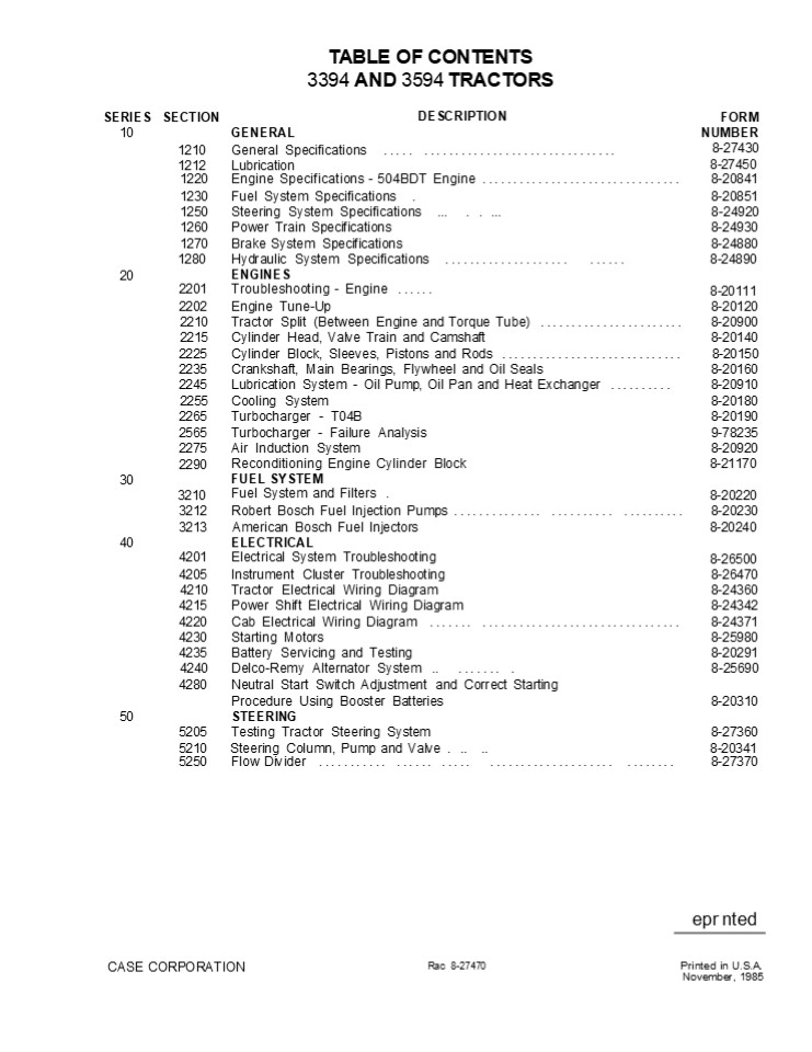
TABLE OF CONTENTS 3394 AND 3594
TRACTORS DESCRIPTION
SERIES 10
SECTION
FORM NUMBER 8-27430 8-27450
GENERAL
1210 General Specifications .....
............................... 1212 Lubrication
1220 Engine Specifications - 504BDT Engine ................................ Engine Specifications - 504BDT Engine ................................ 8-20841
1230 Fuel System Specifications . Fuel System Specifications . 8-20851
1250 Steering System Specifications ... . . ... Steering System Specifications ... . . ... 8-24920
1260 Power Train Specifications Power Train Specifications 8-24930
1270 Brake System Specifications Brake System Specifications 8-24880
20 1280 2201 Hydraulic System Specifications .................... ...... ENGINES Troubleshooting - Engine ...... Hydraulic System Specifications .................... ...... ENGINES Troubleshooting - Engine ...... 8-24890 8-20111
2202 Engine Tune-Up Engine Tune-Up 8-20120
2210 Tractor Split (Between Engine and Torque Tube) ....................... Tractor Split (Between Engine and Torque Tube) ....................... 8-20900
2215 Cylinder Head, Valve Train and Camshaft Cylinder Head, Valve Train and Camshaft 8-20140
2225 Cylinder Block, Sleeves, Pistons and Rods ............................. Cylinder Block, Sleeves, Pistons and Rods ............................. 8-20150
2235 Crankshaft, Main Bearings, Flywheel and Oil Seals Crankshaft, Main Bearings, Flywheel and Oil Seals 8-20160
2245 Lubrication System - Oil Pump, Oil Pan and Heat Exchanger .......... Lubrication System - Oil Pump, Oil Pan and Heat Exchanger .......... 8-20910
2255 Cooling System Cooling System 8-20180
2265 Turbocharger - T04B Turbocharger - T04B 8-20190
2565 Turbocharger - Failure Analysis Turbocharger - Failure Analysis 9-78235
2275 Air Induction System Air Induction System 8-20920
30 2290 3210 Reconditioning Engine Cylinder Block FUEL SYSTEM Fuel System and Filters . Reconditioning Engine Cylinder Block FUEL SYSTEM Fuel System and Filters . 8-21170 8-20220
3212 Robert Bosch Fuel Injection Pumps .............. .......... .......... Robert Bosch Fuel Injection Pumps .............. .......... .......... 8-20230
40 3213 4201 American Bosch Fuel Injectors ELECTRICAL Electrical System Troubleshooting American Bosch Fuel Injectors ELECTRICAL Electrical System Troubleshooting 8-20240 8-26500
4205 Instrument Cluster Troubleshooting Instrument Cluster Troubleshooting 8-26470
4210 Tractor Electrical Wiring Diagram Tractor Electrical Wiring Diagram 8-24360
4215 Power Shift Electrical Wiring Diagram Power Shift Electrical Wiring Diagram 8-24342
4220 Cab Electrical Wiring Diagram ....... ................................ Cab Electrical Wiring Diagram ....... ................................ 8-24371
4230 Starting Motors Starting Motors 8-25980
4235 Battery Servicing and Testing Battery Servicing and Testing 8-20291
4240 Delco-Remy Alternator System .. ....... . 8-25690
4280 Neutral Start Switch Adjustment and Correct Starting
Procedure Using Booster Batteries 8-20310
50 STEERING
5205 Testing Tractor Steering System 8-27360
5210 Steering Column, Pump and Valve . .. .. 8-20341
5250 Flow Divider ........... ...... ..... .................... ........ 8-27370
epr nted
CASE CORPORATION
Rac 8-27470
Printed in U.S.A. November, 1985
2
SERIES SECTION 60
DESCRIPTION
FORM
POWER TRAIN NUMBER
6205 Troubleshooting - Power Shift Transmission ..... 8-26780
6210 Tractor Split (Between Torque Tube and Transmission) ....... ......... 8-27030
6220 Torque Limiter Clutch 8-20980
6325 Hydraulic Pump Drive ....... 8-24140
6230 Power Shift 8-27040
6231 High/Low Range (24 Speed Transmission) ...................... ...... 8-24030
6235 Power Shift Control Valve and Linkage 8-24660
6236 High/Low Range Solenoid (24 Speed Transmission) 8-24712
6240 Four Speed Transmission 8-27050
6241 Transfer Gear Box .......... . ............................. 8-27060
6245 Hydraulic PTO . 8-21030
6251 Rear Axles and Planetaries . . 8-24390
6255 Differential and Differential Lock . 8-21050
6260 Front Axle Differential and Steering Cylinder ........................... 8-26711
6265 Front Axle and Planetary - 3394 Tractor 8-26720
6365 Front Axle and Planetary - 3594 Tractor .................. BRAKES 8-27090
7210 Brake Pressure Regulator Valve ................ 8-24670
7215 Park Lock System 8-21070
7220 Brake Cylinder ....................................................... 8-21080
7240 Brake Valve 8-24470
8202 HYDRAULIC Troubleshooting - Hitch System . 8-21090
8205 Tr toF daulic System ..................................... 8-26631
8210 Hedr ui Her 8-27380
8220 Hydraulic Charging Pump .. .. ..... ... ... ...... ............. 8-21120
8225 Hydraulic Pump . 8-20601
8250 Remote Hydraulic Vules . 8-27320
8255 Flow Divider and PTO Control Valve 8-21140
8260 Differential Lock Solenoid .............. .. 8-24690
8280 Hitch System 8-21151
8290 Break-Away Couplings and Portable Cylinder ......................... 8-20640
9205 ACCESSORIES Troubleshooting - Air Conditioning System 8-20650
9215 Gauging and Testing Air Conditioning System ...... 8-20660
9225 Compressor Isolation, Removal, Installation and Evacuation - Discharging, Evacuation and Charging the Air Conditioning System 8-20670
9235 Servicing Air Conditioner Component 8-24770
9245 Servicing the Cab Blower .............. 8-25580
9250 Operator Seat Adjustments - Non Air/Oil .......................... 8-24750
9250 Operators Seat - Air/Oil 8-25511
9260 Removal of Hood, Grill and Side Panels ......... ........... .. 8-20710
9270 Cab Removal 8-24511
9280 Pedal and Lever Adjustments . ........................................ 8-24680
14205 HOW IT WORKS Digital Instrument Cluster . 8-26550
16430 Electrically Actuated and Hydraulic Operated 12 and 24 Speed Power Shift 8-24731
18225 Case CON TROL Hydraulic ........................................... 8-21350
70
80
90
100
Issued 11-85
Printed in U.S.A.
Rae 8-27470
3
Section
1210
GENERAL SPECIFICATIONS
CASE CORPORATION
Printed in U.S.A. November, 1985
Rac 8-27430
4
https//www.ebooklibonline.com Hello dear
friend! Thank you very much for reading. Enter
the link into your browser. The full manual is
available for immediate download. https//www.ebo
oklibonline.com
5
1210-2
SERIAL NUMBERS
CAB SERIAL NUNIBER PLATE
ENGINE SERIAL NUMBER PLATE
MODEL AND PRODUCT IDENTIFICATION NUMBER PLATE
TRANSMISSION SERIAL NUMBER PLATE
AXLE SERIAL NUMBER
Rae 8-27430
Issued 11-85
Printed in U.S.A.
6
1210-3
DIESEL ENGINE SPECIFICATIONS General Type
..................................................
.............. Six Cylinder, Four Stroke
Cycle, Turbocharged, Valve In Cylinder Head
Firing Order ....................................
.........................................
1-5-3-6-2-4 Bore .................................
......................................... 4-5/8
inch (117.5 mm) Stroke ...........................
..................................................
. 5 inch (127 mm) Piston Displacement
..................................................
.... 504 Cubic inch (8 259 cm) Compression Ratio
..................................................
....................... 15.8 to 1 Cylinder
Sleeves ..........................................
............... Wet Type, Can Be Removed Governor
Engine Speed Without Load ........................
...................... 2280 to 2320 RPM Rated
Engine Speed .....................................
................................. 2100 RPM Engine
Idle Speed .......................................
............................ 725 to 775
RPM Rocker Arm to Valve Clearance, Cold (Exhaust)
................................. 0.025 inch
(0.635 mm) (Intake) ..............................
..... 0.015 inch (0.381 mm) IMPORTANT Rocker arm
to valve clearance adi stment must be made wheñ
the engine is not running. Crankshaft Main
Bearing Journal Diameter .........................
........................... 3.5 inch (88.9 mm)
Rod Bearing Journal Diameter ...... . .. .. ...
. . . .. .. 3.0 inch (76.2 mm) Piston And
Rod Rings Per Piston ...........................
..................................................
..... 3 Compression Rings Per Piston
..................................................
................... 2 Oil Rings Per Piston
..................................................
............................. 1 Type of Piston
Pin ..............................................
........................... Full Float Type of
Bearings .........................................
Replacement Bearings Available, Steel Back With
Aluminum or Copper and Lead Liners Main
Bearings Quantity of Bearings ...................
..................................................
......... 7 Type of Bearings .....................
.................... Replacement Bearings
Available, Steel Back With Aluminum or Copper and
Lead Liners
Rac 8-27430
Issued 11-85
Printed in U.S.A.
7
1210-4 Engine Lubrication System Oil Pressure
......................................... 45 to
60 PSI (310 to 414 kPa)(3.1 to 4.14 bar)
With Engine Warm and Operating at Rated Speed
With a Light Emitting Diode (LED) Service Monitor
Lo- cated in the Digital Instrument Cluster. Type
System ....................................
Constant Pressure and Spray With Piston Oil
Cooling Oil Pump ................................
................................................
Gear Type Oil Filter (2) ........................
.............. Full Flow, Turn on Type, Bypass
Valve in Filter Base Oil Capacity
..................................................
.. With Filters, 21 U.S. Quarts (20
Litres) Without Filters, 23 U.S. Quarts (22
Litres) Oil Cooler ..............................
.................................. Cooled by
Engine Coolant Fuel System Fuel Injection Pump
..................................................
....... Robert Bosch, Type PES Pump Timing
..................................................
. 25 Degrees (BTC) Before Top Center. IMPORTANT
Do not increase past 25 degrees BTC at any time.
The given 25 degrees gi-vet minimum emissions in
tractor operation. Fuel Injectors
..................................................
.... American or Robert Bosch, 17 mm Fuel
Transport Pump ..................................
Plunger Type, a Part of the Fuel Injection
Pump Governor ....................................
........ Variable Speed, a Part of the Fuel
Injection Pump First Stage Fuel Filter
..................................................
...... Full Flow, Turn On Type Second Stage Fuel
Filter ...........................................
.......... Full Flow, Turn On Type Water Trap and
Drain for Fuel Tank ..............................
... Location is in Bottom of Fuel Tank Fuel Tank
Capacity .........................................
.............. 85 U.S. Gallons (322 Litres) Fuel
Level Indicator ..................................
...... Liquid Crystal Display (LCD) Bar
Indicator Located in the Digital Instrument
Cluster Hand Primer Pump .........................
............... Location is on Top of Fuel
Transport Pump Fuel Strainer .....................
....................... Location is at Bottom of
Fuel Transport Pump
Qec 8-27430
Issued 11-85
Printed in U.S.A.
8
1210-5
GENERAL TRACTOR SPECIFICATIONS Air Intake System
Type ...............
. Dry Type Air Induction System, Two Stage,
Aspirated System With Service Indicator on
Digital Instrument Cluster
Cooling System Capacity ........................
......................................... 44 U.S.
Quarts (41.6 Litres) Type .......................
................................ Pressure System,
Thermostat Controlled, Bypass, Impeller Type Pump
Radiator .........................................
..................... Heavy Duty Fin and Tube
Type Thermostats .................................
................... Two, Starts to Open at
Approximately 175 F (79 C), Fully Open at 202
F (94 C) Pressure Cap ...........................
.................................... 10 PSI (69
kPa)(0.69 bar) Water Level . . ..... . . . . . .
. . . . . . . . . . . . . . . . . . . . . . . . .
. . . . . . . . . . Light Emitting .Diode (LED)
Service Monitor Located in the Digital Instrument
Cluster Coolant Temperature .....................
................. Liquid Crystal Display (LCD)
Bar Indicator Located in the Digital Instrument
Cluster Electrical System Type of System
..................................................
........... 12 Volt, Negative Ground Batteries
.................................................
Two 12 Volt Batteries Connected in Parallel, AABM
Group Size TFG10-600, Rated in 1.255 to 1.265
Specific Gravity. Discharge Rate 300 Amperes at
0 F. Alternator .................................
............. 12 Volt, 105 Ampere Output,
Negative Ground With a Light Emitting Diode (LED)
and a Liquid Crystal Display (LCD) Service
Monitors Lo- cated in the Digital Instrument
Cluster. Voltage Regulator .......................
.......... 12 Volt, Solid State, Inside Component
of Alternator Starter Motor ......................
..................................... 12 Volt
With Solenoid Switch Head Lamps (2)
........................................... 12
Volt, 40/60 Watt Sealed Beam High-Low Front Flood
Lamps (4 Max) ....................................
......... 12 Volt, 50 Watt, Sealed Beam Rear
Flood Lamps (4 Max) ..............................
................ 12 Volt, 50 Watt, Sealed
Beam Flasher Lamps (2) with Direction Turn
Signals .................................... 12
Volt, Amber Lens Tail Lamps (2)
..................................................
................... 12 Volt, Red Lens Electrical
System Circuit Breaker Primary Circuit
............................................. 12
Volt, Three 50 Ampere Circuit Breakers Connected
in Parallel, 150 Ampere Rating, 112.5 Ampere
Minimum Continuing Ca- pacity. Auxiliary Circuit
............................................. 12
Volt, Four 50 Ampere Circuit Breakers
Issued 11-85
Printed in U.S.A.
Rac 8-27430
9
1210-6 Electrical System
Bulb And Lamp Replacement Instrument Cluster
Lamps . . . .. ... . . .. ..
. ... . . . .... .. . .
...... No. 73 No. 93
Dome Lamp Bulb ...............
Console Lamp Bulb ...............................
........................................ No.
194 Flasher Lamp Bulb ...........................
............................................ No.
1156 Head Lamp ..................................
............................................ No.
4652 Front and Rear Flood Lamp ...................
........................................ No.
A48265 Tail Lamp Bulb ............................
................................................
No. 168 Fuse Replacement Instrument Cluster
..................................................
................... 3.0 Ampere Automatic Shutoff
Solenoid ........................................
.................... 7.5 Ampere Tail Lamp
..................................................
............................ 15 Ampere Lamp
Switch Feed .....................................
................................ 25
Ampere Accessories ..............................
............................................. 3.0
Ampere Ether Switch and Cab Relay
..................................................
.......... 20 Ampere Head Lamp Low J3eam
..................................................
................ 15 Ampere Head Lamp High Beam
..................................................
............... 15 Ampere Front Flood Lamps . . .
. . . . . . . . . . . . . . . . . . . . . . . . .
. . . . . . . . . . . . . . . . . . . . . . . . .
.. . . . . . . . . . . . . . 25 Ampere Radio
and Night Lamp ...................................
............................... 10
Ampere Ignition Switch ...........................
.............................................. 25
Ampere Flasher and Dome Lamp .....................
........................................... 15
Ampere Rear Flood lamps .........................
............................................. 25
Ampere Wiper ....................................
............................................. 7.5
Ampere Blower ...................................
............................................. 15
Ampere Cigarette Lighter ........................
...............................................
15 Ampere Instrument Reset . . . . . . .. .
. 5.0 Ampere Transmission Control Differential
Lock ............................................
...... 20 Ampere Range Switch ...................
..................................................
.... 1.0 Ampere Rear Wiper and Washer (If
equipped) ........................................
............ 10 Ampere Tractor Brakes Type
..................................................
.. Hydraulic, Power Assistance,
Self-Adjusting, Several Plate Wet Type
Differential Brakes. Power Shift
Transmission Type ..............................
............. Three Speed, or Six Speed, Compound
Planetary with Hydraulically Actuated Clutches
and a Four Speed Gear Section Gear Selection
......................................... 12
Speeds Forward and Three Speeds Reverse or 24
Speeds Forward and Three Speeds Reverse Shift
Control ..........................................
........... Actuated by a Lever on the Console.
Oil Cooler ...................................
Transmission, Remote Hydraulics, Steering and
Brake Oil Parking Lock System Parking Lock
..................................................
......... Actuated by Gear Shift
Lever Differential Lock Type ...................
......................... Electrically Controlled
by Switch on Control Console and Hydraulically
Actuated Rac 8-27430 Issued 11-85 Printed in
U.S.A.
10
1210-7
Hydrostatic Power Steering
2a P
f
y p Capacity" at 21'00 RPM '.........."......
"."........................'.. ". r. U . 13
HPM" 2 thin) Steering Pump ...................
.................. Hydrostatic Type, Actuated By
the Steering Wheel Steering Cylinder
..................................................
.......... Double Action Cylinder Hitch
System Type of Sensing .........................
................................................
Lower Link Type of Control ......................
..................................................
. Hand Lever Type of Valve ......................
.............................. Three
Position-Lift, Hold and Lower Type of Draft Arms
......................... Rigid, Swing Type or
Extendable With Lower Float Adjuster Type of
Hitch ............................................
................... Three Point, Category
III Conversion Hitch Coupler (Available)
...............................................
Category III To II Lift Capacity at 24 inch (610
mm) Behind Lift Point ...........................
...... 7,750 lb (3 515 kg) Remote Hydraulic
System Pump ....................................
....... Axial Piston Pump, Pressure-and Flow
Compensated. Type Remote Valve
.............................................
Closed Center, Two to Four Sections, Hand Lever
Control, 1st Section Prior- ity, 1st/2nd Section
Load Check on "B" Port, 3rd Section Load Check
Op- tional-Single or Dual, Variable Flow Control
for Each Section. Pump Capacity at 2100 Engine
RPM ................................... 28 to 30
GPM (106 to 114 I/min) Maximum System Pressure
............................. 2250 PSI (15 503
kPa)(155.03 bar) With a Light Emitting Diode
(LED) Service Monitor for Both Transmission Oil
Pressure and Transmission Filter Located in the
Digital Instrument Cluster Couplings
...................................... ASAE R366
Standard, Fast Removal, Break Away Type Power
Takeoff PTO Type ................................
.............................. Independent of
Transmission Type Sof Clutch .....................
..............................................
Hydraulic Actuated Rotations ....................
..................................................
........... Clockwise Spline Size
.................................................
21 Splines, 1.375 inch (34.9 mm) Diameter PTO
Speed ............................................
... 1000 RPM Shaft Speed at 2100 Engine
RPM Drawbar Standard or Yoke Type
................................... Full Swing,
Roller Mount, Takes a 1-1/2 inch (38.1 mm)
Diameter Pin. Mechanical Front Drive (MFD) Front
Axle ............................................
.. Spiral Bevel With Planetary Reduction in Hub
Interaxle Ratio - Front/Rear ....................
................................................
1.332 Differential Oil Capacity
..................................................
.... 9 U.S. Quarts (8.5 litres) Planetary Oil
Capacity .......................................
1.5 U.S. Quarts (1.4 litres) each planetary
Rac 8-27430
Issued 11-85
Printed in U.S.A.
11
2201-2d INSTALLATION INSTRUCTIONS FOR M20614
TEFLON VALVE SEAL KIT Special Tools Required
M20617 VALVE GUIDE CUTTING TOOL
M20624 SEAL INSTALLATION TOOL
VALVE SPRING COMPRESSOR
STEP 1
IMPORTANT Make a mark on the valves, rotators,
spring retainers and keepers. This will make sure
that the parts are installed in the original
location. STEP 3
VALVE KEEPERS
Remove the cylinder heads. See Section 2215 of
the Service Manual for removal of the cylinder
heads.
Push down the valve springs and remove the valve
keepers.
STEP 2
STEP 4
Use a valve spring compressor to push down the
valve springs.
Remove the valve rotators or the valve spring re-
tainers. Revised 7-83 Printed in U S A
Rac 8-20111
12
2201-25
STEP 5
Remove the valve springs.
Remove the valves.
STEP 6
STEP 9
Remove the spring seats.
Clean the cylinder head completely, removing all
the carbon and other deposits. Check for cracks
and for any sign of damage, existing in the area
of the fire ring contact.
STEP 7
STEP 10
VALVE STEM SEAL
Clean the valves with a fine wire brush that is
power driven. Remove all carbon and varnish de-
posits. Do not scratch the valve stems.
Remove the valve stem seals.
Rac 8-20111
Revised 7-83
Printed in U S.A
13
2201-26
STEP 11
STEP 13
MIN IMUM 1/16" WIDE FLAT
Put clean eng ine oil on the valves befo re
install ing the val ves in the cylin der
head. STEP 14
VALVE SPRING SEAT
PLASTIC CAP
Check the top surface of the valve guide. There
must be a minimum of a 1/16 (0.0625 mm) wide
flat around the complete top surface. STEP
12 Instal I the spring seats. Put the plastic
installation cap on the end of the valve stem.
The plastic cap prevents the sharp edges on
the valve stem grooves from cutting the valve
seal. NOTE One M20614 kit is required for one
cylinder head.
Use the M20617 tool in an electr ic d ril I to
give the necessary flat area on the val ve
guide. IMPORTANT Do not go over 450 RP/\4 N/hen
dr//l- ing.
Revised 7-83
Pri nted in U S A
Rac 820111
14
2201-27
STEP 15
STEP 17
TEFLON VALVE SEAL
Put the valve seal over the plastic cap. Hold
your thumb against the white seal insert to keep
the insert from coming out. Push the valve seal
down so that the seal jacket is against the top
of the valve guide. Remove the installation cap.
Keep the cap since the cap will be used again.
Install the valve spring. Either end of the valve
spring can be installed in the valve spring seat
because both ends of the spring are closed.
STEP 18
STEP 16
Install the valve rotators or the valve spring
retain- ers (flat side up).
IMPORTANT Install the valve rotators or the
valve spring retainers with the original valves
because these parts are worn as counterparts of
each other.
Use the M20624 tool and push the seal down over
the valve guide until the seal is level with the
top of the guide.
Rae 8-20111
Revised 7-83
Printed in U.S.A.
15
2201-28 STEP 19
STEP 22
Push down the valve springs with a spring
com- pressor.
Remove the spring compressor. Hit the end of the
valve stems with a soft hammer to seat the valve
keepers.
STEP 20
STEP 23
VALVE STEM SEAL
Install teflon seals on all the intake and
exhaust valves.
Install a new valve seal in the lower valve stem
groove.
STEP 24
STEP 21
Install the cylinder heads. See Section 2215 of
the Service Manual for installation of the
cylinder
Install the valve keepers in the upper valve stem
groove. Rac 8-20111
heads.
Revised 7-83 Printed in U S A.
16
2202-4 ENGINE TUNE-UP PROCEDURE Checking The
Crankshaft Damper Pulley (If Equipped)
STEP 1
STEP 2
PULLEY
Loosen the pulley to crankshaft bolt.
The recommendation for the change interval for
the crankshaft damper pulley is 2000 hours maxi-
mum. At any time over 1500 hours change the
pulley at any engine overhaul or tune-up.
NOTE See Section 9260 or 9360 of the Service
Manual for hood removal and Section 2255 for
radiator and alternator belts removal.
Every 500 hours and during the engine tune-up,
visually check the rubber element for areas where
the rubber is coming off or cracked. Check the
alignment of the marks between the inner and
outer units. If the marks move, the damper pulley
must be replaced. Go to Step 2 for pulley removal.
STEP 3
RUBBER ELEMENT CRANKSHAFT DAMPER
PULLEY V MARKS ON FRONT SIDE OF PULLEY
Remove the bolt, lockwasher and the
retainer washer.
Rac 8-20120
Issued 8-78
Printed in U.S.A.
17
2202-5
STEP 4
STEP 7
TIMING POINTERS
USE PULLER WITH BOLTS
Remove the timing pointer.
Leave the puller on the pulley and put the puller
in a vise. Loosen the bolts that hold the damper
(if equipped) to the pulley.
IMPORTANT Use a puller with bolts to remove the
pulley. Do not pull or hit the pulley or the
viscous damper. Serious damage to the pulley,
damper and the rubber sleeve in the pulley can
result.
STEP 8
STEP 5
Remove the bolts and the washers.
STEP 9
Remove the pulley.
STEP 6
Remove the damper.
Do not lose the pulley retaining key.
Rac 8-20120
Issued 8-78
Printed in U.S.A.
18
2202-6 STEP 10
STEP 13
Fasten the puller to the front side of a new
pulley and put the puller in a vise.
Tighten the bolts to a torque of 110 to 132 ft.
lbs. (149 to 179 Nm)(14.9 to 17.9 kgm). Remove
the puller.
STEP 11
STEP 14
Install the damper to the pulley. The flat side
of the damper is against the pulley.
Replace the key if the key shows damage.
STEP 15
STEP 12
Install the pulley to the crankshaft. Install the
bolt, lockwasher and retaining washer.
Install the bolts and new hardened washers.
NOTE The hub side of the pulley must be put
against the engine. Align the crankshaft key with
the slot in the pulley. Issued 8-78 Printed in
U.S.A.
Rae 8-20120
19
2202-7
STEP 16
STEP 17
Tighten the bolt to a torque of 100 to 110 ft.
lbs. (136 to 149 Nm)(13.6 to 14.9 kgm).
Install the timing pointer.
PULLEY
VISCOUS DAMPER
RUBBER SLEEVE
CRANKSHAFT
100 TO 110 FT. LBS.
110 TO 132 FT. LBS.
Issued 8-78
Printed in U.S.A.
Rac 8-20120
20
2202-8
Checking Top Dead Center
IMPORTANT Before checking top dead center,
check the alignment marks on the pulley, see Step
1. STEP 18
sTEP 20
Remove the front valve cover.
STEP 21
Remove the breather tube.
STEP 19
Turn the engine over until the Top Dead Center
mark on the crankshaft pulley is aligned with the
timing pointer.
Remove the nuts, washers and rubber gaskets
from the front valve cover.
Issued 8-78
Printed in U.S.A.
Rac 8-20120
21
Suggest If the above button click is invalid.
Please download this document first, and then
click the above link to download the complete
manual. Thank you so much for reading
22
2202-9
STEP 22
STEP 25
NUT
Loosen the Number One nozzle fuel line.
Remove the rocker arm retaining studs, nuts and
washers.
STEP 26
STEP 23
Loosen the retaining nut of the Number One noz-
zle using a 7/8" crowsfoot wrench (Snap-On Tool
Part Number AN-8508-14, flared nut type or AN-
8506-8, open end type) with an extension and
ratchet wrench.
Remove the rocker arm assembly.
STEP 24
LOOSEN
STEP 27
TURN
REMOVE
REMOVE
Remove the leak off line from the Number One fuel
injection nozzle to the fuel pump. Loosen the
leak off line between the Number One and the
Number Two fuel injection nozzles. NOTE Removal
of fuel lines will prevent damage to the lines
when removing the exhaust valve spring. Rac
8-20120
Remove the leak off line and turn the fuel
injedtor nozzle towards the rear of the engine.
Remove the Number One cylinder exhaust push rod.
Issued 8-78
Printed in U.S.A.
23
https//www.ebooklibonline.com Hello dear
friend! Thank you very much for reading. Enter
the link into your browser. The full manual is
available for immediate download. https//www.ebo
oklibonline.com
Recommended

