
CASE CX460 TIER 3 CRAWLER EXCAVATOR Service Repair Manual Instant Download
Title:
CASE CX460 TIER 3 CRAWLER EXCAVATOR Service Repair Manual Instant Download
Description:
CASE CX460 TIER 3 CRAWLER EXCAVATOR Service Repair Manual Instant Download –
Number of Views:1
Title: CASE CX460 TIER 3 CRAWLER EXCAVATOR Service Repair Manual Instant Download
1
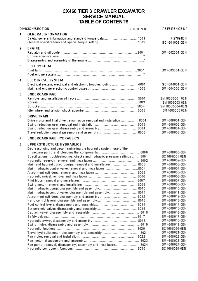
CX460 TIER 3 CRAWLER EXCAVATOR SERVICE
MANUAL TABLE OF CONTENTS SECTION N
DIVISION/SECTION
REFERENCE N
- GENERAL INFORMATION
- Safety, general information and standard torque
data ..................................... 1001 - General specifications and special torque setting
........................................... 1002 - ENGINE
- Radiator and oil-cooler ..........................
..................................................
........ 2001 - Engine specifications ............................
..................................................
................ - Disassembly and assembly of the engine
..................................................
............ - FUEL SYSTEM
- Fuel tank ........................................
..................................................
................ 3001 - Fuel engine system ...............................
..................................................
............... - ELECTRICAL SYSTEM
- Electrical system, electrical and electronic
troubleshooting ............................ 4001
Main and engine electronic control boxes
..................................................
..... 4003 - UNDERCARRIAGE
- Removal and installation of tracks
..................................................
................. 5001 Rollers ..
..................................................
..................................................
...... 5003 - Sprocket..........................................
..................................................
............... 5004 - Idler wheel and tension shock absorber
..................................................
........ 5005 - DRIVE TRAIN
- Drive motor and final drive transmission removal
and installation ................... 6001 Swing
reduction gear, removal and installation
...............................................
6003 - Swing reduction gear, disassembly and assembly
.......................................... 6004
7-27691EN SC4601002-0EN
SM4602001-0EN
SM4603001-0EN
SC4604001-0EN SM4604003-0EN
SM160B5001-0EN SM4605003-0EN SM160B5004-0EN
SM4605005-0EN
SM4606001-0EN SM4606003-0EN SM4606004-0EN
SM4606005-0EN
SM4608000-0EN SC4608001-0EN SM4608002-0EN
SM4608003-0EN SM4608004-0EN SM4608005-0EN
SM4608006-0EN SM4608007-0EN SM4608008-0EN
SM4608010-0EN SM4608011-0EN SM4608012-0EN
SM4608013-0EN SM4608014-0EN SM4608015-0EN
SM4608016-0EN SM4608017-0EN SM4608018-0EN
SM4608019-0EN SC4608020-0EN SM4608021-0EN
SM4608022-0EN SM4608023-0EN SM4608024-0EN
SC4608030-0EN
2
DIVISION/SECTION SECTION N
REFERENCE N
9 UPPERSTRUCTURE Upperstructure, turntable and
counterweight.....................................
................ 9002 Boom, dipper and bucket
..................................................
................................. 9003 Seat,
removal and installation..........................
..................................................
9004 Cab and cab equipment.......................
..................................................
............ 9005 Air conditioning unit
disassembly and assembly..........................
...................... 9007 Large size hydraulic
schematics .......................................
...............................Pocket Large size
electrical schematics ............................
SM4609002-0EN SM4609003-0EN SM4609004-0EN
SM4609005-0EN SM4609007-0EN 87574463A 87574470A
Consult the Engine Service Manual NOTE CNH
Company reserves the right to make changes in the
specification and design of the machine without
prior notice and without incurring any obliga-
tion to modify units previously sold. The
description of the models shown in this manual
has been made in acco rd- ance with the
technical specifications known as of the date of
design of this document.
Lep SM460TOC-0EN
Issued 09-07
3
Section 1001
1001
SAFETY, GENERAL INFORMATION AND TORQUE
SPECIFICATIONS
CNH
Lep 7-27691EN
4
https//www.ebooklibonline.com Hello dear
friend! Thank you very much for reading. Enter
the link into your browser. The full manual is
available for immediate download. https//www.eb
ooklibonline.com
5
1001-2
TABLE OF CONTENTS GENERAL INFORMATION
..................................................
..................................................
...................................
3 SAFETY..........................................
..................................................
..................................................
....................... 4 STANDARD TORQUE DATA
FOR CAP SCREWS AND NUTS...........................
..................................................
.. 6
WARNING This symbol is used in this manual to
indicate important safety messages. Whenever you
see
! this symbol, carefully read the message that
follows, as there is a risk of serious injury.
Lep 7-27691EN
Issued 02-06
6
1001-3
GENERAL INFORMATION Gears
Cleanning
Clean all metal par ts except bear ings, in a
suitab le cleaning so lvent or b y ste am clea
ning. Do not use caustic sod a for st eam clean
ing. After clea ning, dry and put o il on al l
pa rts. Clea n o il p assages with compressed
air. Clean bearings in a suitable cleaning
solvent, dry th e be arings completely an d pu
t oil on the bearings. Inspection Check a ll
parts whe n th e pa rts ar e disassemb led.
Replace a ll pa rts t hat h ave wear o r d amage.
Small scoring or g rooves can be r emoved wit
h a ho ne o r crocus clot h. Com plete a visual
in spection for indications of w ear, p itting
an d the r eplacement o f parts necessary to
prevent early failures. Bearings Check b earings
f or easy actio n. If be arings ha ve a loose f
it or ro ugh act ion r eplace t he bea ring. Wash
bearings with a suitable cleaning solvent and
permit to air dr y. DO NO T DR Y BEARIN GS WITH
COMPRESSED AIR. Needle bearings Before y ou pr
ess nee dle bearings in a bore always remove any
metal protrusions in the bore or edge of the
bore. Before you press bearings into position put
petroleum jelly on the inside and outside
diameter of the bearings.
Check all gears for wear and damage. Replace
gears that have wear or damage. Oil seals,
O-rings and gaskets Always install new oil seals,
O-rings and gaskets. Put petroleum jelly on
seals and O-rings. Shafts Check all shaf ts t hat
ha ve w ear or dam age. Ch eck the bearing a nd
oil seal surfaces of t he sha fts f or
damage. Service parts Always install gen uine
Case ser vice par ts. When ordering refer to the
Parts Catalog for the correct part number of t
he g enuine Case r eplacement ite ms. Failures
due to the use of other than genuine Case
replacement parts are not covered by
warranty. Lubrication Only use t he o ils and
lubr icants spe cified in t he Operators or
Service Ma nuals. Failures du e to th e use o f
no n-specified o ils an d lub ricants are not
covered by warranty.
Lep 7-27691EN
Issued 02-06
7
1001-4
SAFETY
This symbol means ATTENTION! BECOME ALERT! YOUR
SAFETY IS INVOLVED. The message that follows the
! symbol contains important information about
safety. Carefully
read the message. Make sure you fully understand
the causes of possible injury or death.
To prevent injury always follow the Warning,
Caution and Danger notes in t his section and
throughout the manual. Put th e warning tag sh
own be low on th e key for the keyswitch w hen
ser vicing or repairing the machine . One
warning t ag is supplied with ea ch m achine.
Additional tags Part Number 331-4614 are
available from your service parts supplier .
WARNING Before starting engine, study
Operators Manual safety messages. Read all
safety signs on machine. Clear the area of other
persons. Learn and practice safe use of controls
before operating.
! It is your responsibility to understand and
follow manufacturers instructions on machine
operation, service and to observe pertinent laws
and regulations. Operators and Service Manuals
may be obtained from your Case dealer.
WARNING Read the operators manual to
! familiarize yourself with the correct control
functions.
WARNING If you wear clothing that is too loose
or do not use the correct safety equipment for
your job, you can be injured. Always wear
clothing that will not catch on objects. Extra
safety equipment that can be required includes
hard hat, safety shoes, ear protection, eye or
face protection, heavy gloves and reflector
clothing.
WARNING Operate the machine and
! equipment controls from the seat position
only. Any other method could result in serious
injury.
!
WARNING This is a one man machine, no riders
allowed.
!
WARNING When working in the area of the
! fan belt with the engine running, avoid loose
clothing if possible, and use extreme caution.
WARNING When doing checks and tests
! on the equipment hydraulics, follow the
procedures as they are written. DO NOT change
the procedure.
WARNING When putting the hydraulic cylinders on
this machine through the
! necessary cycles to check operation or to
remove air from a circuit, make sure all people
are out of the way.
Lep 7-27691EN
Issued 02-06
8
1001-5
WARNING When servicing or repairing the
machine, keep the shop floor and operators
WARNING Use insulated gloves or mittens when
working with hot parts.
!
! compartment and steps free of oil, water,
grease, tools, etc. Use an oil absorbing
material and/or shop cloths as required. Use
safe practices at all times.
WARNING Lower all attachments to the
! ground or use stands to safely support the
attachments before you do any maintenance or
service.
WARNING Some components of this
! machine are very heavy. Use suitable lifting
WARNING Pin sized and smaller streams of
hydraulic oil under pressure can penetrate the
skin and result in serious infection. If
hydraulic oil under pressure does penetrate the
skin, seek medical treatment
equipment or additional help as instructed in
this Service Manual.
! immediately. Maintain all hoses and tubes in
WARNING Engine exhaust fumes can cause death.
If it is necessary to start the
good condition. Make sure all connections are
tight. Make a replacement of any tube or hose
that is damaged or thought to be damaged. DO NOT
use your hand to check for leaks, use a piece of
cardboard or wood.
! engine in a closed place, remove the exhaust
fumes from the area with an exhaust pipe
extension. Open the doors and get outside air
into the area.
WARNING When the battery electrolyte is frozen,
the battery can explode if (1), you try to
charge the battery, or (2), you try to jump
WARNING When removing hardened pins such as a
pivot pin, or a hardened shaft, use
! start and run the engine. To prevent the
! a soft head (brass or bronze) hammer or use
battery electrolyte from freezing, try to keep
the battery at full charge. If you do not follow
these instructions, you or others in the area
can be injured.
a driver made from brass or bronze and a steel
head hammer.
WARNING When using a hammer to remove and
install pivot pins or separate
! parts using compressed air or using a
grinder, wear eye protection that completely
encloses the eyes (approved goggles or other
approved eye protectors).
WARNING Use suitable floor (service) jacks or
chain hoist to raise wheels or tracks off the
floor. Always block machine in place with
suitable safety stands.
!
Lep 7-27691EN
Issued 02-06
9
1001-6 STANDARD TORQUE DATA FOR CAP SCREWS AND
NUTS Tightening of cap screws, nuts Tighten
alternately so that tightening torque can be
applied evenly. The numbers in the figure below
indicate the order of tightening.
JS00481A Cap screws which have had Loctite used
(white residue remains after removal) should be
cleaned with loght oil or suitable cleaning
solvent and dr ied. Apply 2- 3 drops of Loctite
to the thread portion of the cap screw and then
tighten. Torque table Tighten cap screws and nuts
according to the table below if there are no
other special instructions.
Cap Screw Name Size (Size) Cap Screw Name Size (Size) Cap Screw Name Size (Size) M6 M8 M10 M12 M14 M16 M18 M20
Cap Screw Spanner mm 10 13 17 19 22 24 27 30
Cap Screw Spanner in. 0.39 0.51 0.67 0.75 0.87 0.95 1.06 1.18
Cap Screw Tightening torque Nm 6.9 19.6 39.2 58.8 98.1 156.9 196.1 294.2
Cap Screw Tightening torque lb-ft 5.1 14.5 28.9 43.4 72.3 115.7 144.6 217
Socket Head Cap Screw Spanner mm 5 6 8 10 12 14 14 17
Socket Head Cap Screw Spanner in. 0.20 0.24 0.32 0.39 0.47 0.55 0.55 0.67
Socket Head Cap Screw Tightening torque Nm 8.8 21.6 42.1 78.5 117.7 176.5 245.2 343.2
Socket Head Cap Screw Tightening torque lb-ft 6.5 15.9 31.1 57.9 86.9 130.2 181 253.2
Lep 7-27691EN
Issued 02-06
10
Section 1002
1002
SPECIFICATIONS AND SPECIAL TORQUE SETTINGS
CNH
Lep SC4601002-0EN
11
1002-2
TABLE OF CONTENTS
WARNING This symbol is used in this manual to
indicate important safety messages. Whenever you
see this symbol, carefully read the message
which follows. Your safety depends on it.
!
TYPE, SERIAL NUMBER AND YEAR OF MANUFACTURE OF
THE MACHINE.......................................
..................................................
............ 5 Machine ...........................
..................................................
..................................................
........................................ 5 Engine
..................................................
..................................................
..................................................
.................... 5 Serial numbers of the
components .......................................
..................................................
..................................... 5 FLUIDS
AND LUBRICANTS ...................................
..................................................
..................................................
..... 6 Hydraulic fluid ..........................
..................................................
..................................................
................................ 6 Transmission
component oil ....................................
..................................................
..................................................
6 Grease ........................................
..................................................
..................................................
............................. 6 Engine Oil
..................................................
..................................................
..................................................
.............. 7 Engine fuel, maintenance of fuel
filters and fuel storage .........................
..................................................
.................. 8 Anti-freeze/Anti-corrosion..
..................................................
..................................................
.....................................
10 Environment ...................................
..................................................
..................................................
........................ 10 Plastic and resin
parts.............................................
..................................................
.................................................
10 SPECIFICATIONS ...............................
..................................................
..................................................
...................... 11 Main data
..................................................
..................................................
..................................................
............. 11 Performance .....................
..................................................
..................................................
..................................... 11 Complete
machine dimensions ...............................
..................................................
.................................................
11 Main body dimensions ..........................
..................................................
..................................................
................. 11 Engine ......................
..................................................
..................................................
..............................................
12 Cooling system ................................
..................................................
..................................................
...................... 12 Capacity of coolant and
lubricants .......................................
..................................................
.................................... 12 Hydraulic
oil filter........................................
..................................................
..................................................
............ 12 Fuel filter ......................
..................................................
..................................................
..........................................
12 Operating devices .............................
..................................................
..................................................
..................... 13 Hydraulic
system............................................
..................................................
..................................................
........ 14 Swing unit ...........................
..................................................
..................................................
................................... 16 Travel
lower body........................................
..................................................
..................................................
........... 16 Work Unit .........................
..................................................
..................................................
...................................... 17 Digging
force (ISO 6015) .................................
..................................................
..................................................
...... 18 COMPONENT WEIGHT.......................
..................................................
..................................................
...................... 19 Major component weight
..................................................
..................................................
........................................
19 Bucket weight..................................
..................................................
..................................................
....................... 20 Other component weight
..................................................
..................................................
........................................
21 DIMENSIONS AND WEAR LIMIT OF THE TRACK
ASSEMBLY .........................................
......................................... 22
Sprocket .........................................
..................................................
..................................................
........................ 22 Idler
wheel.............................................
..................................................
..................................................
................. 23 Lep SC4601002-0EN Issued
03-07
12
1002-3 Upper roller ..............................
..................................................
..................................................
...............................24 Lower roller
..................................................
..................................................
..................................................
...........25 Track...............................
..................................................
..................................................
........................................26 DIMENSI
ONS AND WEAR LIMITS OF ATTACHEMENT MOBILE JOINTS
..................................................
................27 1. Boom foot/Frame
..................................................
..................................................
................................................27
2. Boom cylinder foot/Frame......................
..................................................
..................................................
.............28 3. Boom cylinder
head/Boom.........................................
..................................................
...........................................28 4.
Arm cylinder foot/Boom ...........................
..................................................
..................................................
...........29 5. Boom/Arm.........................
..................................................
..................................................
..................................29 6. Arm
cylinder head/Arm ................................
..................................................
..................................................
.......29 7. Bucket cylinder foot/Arm
..................................................
..................................................
.....................................30 8.
Connecting rod/Arm................................
..................................................
..................................................
............30 9. Compensator/Bucket
..................................................
..................................................
..........................................30 10.
Connecting rod/Compensator/Bucket cylinder head
..................................................
..........................................31 11.
Arm/Bucket .......................................
..................................................
..................................................
................31 SHIMS FOR ADJUSTING ATTACHMENT
GAPS .............................................
..................................................
...........32 For boom foot .....................
..................................................
..................................................
....................................32 SPECIAL
TORQUE SETTINGS...................................
..................................................
.................................................3
3 MACHINE OVERALL DIMENSIONS ....................
..................................................
..................................................
......36
Lep SC4601002-0EN
Issued 03-07
13
1002-5 TYPE, SERIAL NUMBER AND YEAR OF
MANUFACTURE OF THE MACHINE For all part orders,
request for information or assistance, always
specify the type and the serial number of the
machine to your Case dealer. Fill in the
following lines with the required information
Type, serial number, year of manufacture of the
machine and the serial numbers of the hydraulic
and mechanical components. Machine
1 2
3
CT04A171A (1) Type ...............................
..................................................
..................................................
.................................... (2) Serial
number ...........................................
..................................................
..................................................
......... (3) Year of manufacture.................
..................................................
..................................................
.......................... Engine Make and
type..............................................
..................................................
..................................................
........... Serial number.........................
..................................................
..................................................
................................. Serial numbers
of the components Hydraulic pump
..................................................
..................................................
..................................................
..... Swing reduction gear .......................
..................................................
..................................................
....................... Travel reduction gears
..................................................
..................................................
............................................. Cont
rol valve ........................................
..................................................
..................................................
...................
Lep SC4601002-0EN
Issued 03-07
14
1002-6
FLUIDS AND LUBRICANTS Lubricants must have the
correct properties for each application.
WARNING The conditions of use for individual
fluids and lubricants must be respected.
!
Hydraulic fluid CASE/AKCELA hydraulic fluid is
specially designed for high pressure applications
and for the CASE hydraulic system. The type of
fluid to be used depends on the ambient
temperature. Temperate climates -20C to 40C
(-4 to 104 F) CASE/AKCELA HYDRAULIC EXCAVATOR
FLUID (MS 1230. ISO VG 46. DIN 51524 PART 2
HV) Hot climates 0C to 50C (32 to 122
F) CASE/AKCELA AW HYDRAULIC FLUID 68 HV (MS
1216. ISO VG 68. DIN 51524 PART 3 CATEGORY
HVLP) Cold climates -25C to 20C (-13 to 68
F) CASE/AKCELA AW HYDRAULIC FLUID 32 (MS 1216.
ISO VG 32. DIN 51524 PART 2) Biodegradable fluid
-30C to 40C (-22 to 104 F) This
yellow-colored fluid is miscible with standard
fluid. If used to change standard fluid, it is
advised to drain the circuit completely before
refilling with this fluid. CASE/AKCELA HYDRAULIC
EXCAVATOR FLUID BIO (MS 1230. ISO VG 46. DIN
51524 PART 2 HV) Transmission component
oil Extreme pressure oil used for enclosed
transmission components. CASE/AKCELA GEAR 135H
EP (SAE 80W-90. API GL 5. MIL-L-2105 D. MS 1316.
ZF TE-ML 05A) Grease CASE/AKCELA MOLY GREASE
251H EP-M (251H EP-M. NLGI 2) "Extreme Pressure"
multipurpose grease with lithium soap and
molybdenum disulphide. CASE/AKCELA MULTIPURPOSE
GREASE 251H EP (251H EP. NLGI 2) "Extreme
Pressure" multipurpose grease with lithium soap
and calcium. CASE/AKCELA PREMIUM GREASE EP2
(NLGI 2) "Extreme Pressure" multipurpose grease
with lithium soap. Hydraulic breakers CASE/AKCELA
MULTIPURPOSE GREASE 251H EP (NLGI 2).
Lep SC4601002-0EN
Issued 03-07
15
1002-7
Engine Oil THE CASE/AKCELA No. 1 engine oil is re
commended for your e ngine. Th is o il en sures
p roper lubr ication of your engine for all
operating conditions. If the CASE/AKCELA
Multigrade "No. 1 EN GINE OIL" cannot be
obtained, use the oil corresponding to one of
the following categories ACEA E7. API CI-4.
CP02N001
Oil viscosity / Oil range
1 2 2 3 3
CT02M001
- 1) With mineral base
- With semi-synthetic base
- With synthetic base
Lep SC4601002-0EN
Issued 03-07
16
- 1002-8
- Engine fuel, maintenance of fuel filters and fuel
storage - In order to meet the emission control regulation
of 3rd-stage, the engine components have been
made precisely and they are to be used under
high-pressure conditions. - Therefore, the specified fuel must be used for
the engine. - As a matter of course, not only the guarantee
will not be given for the use of a fuel other
than the specified but also it may invite a
serious breakdown. - In addition, since suitable specifications for
the fuel filter elements have been established
for this engine, use of the gen- uine filter is
essential. - The following describes the specifications and
the requirements of the fuel to be applied, and
maintenance of the fuel and the fuel elements. - Fuel to be applied
- Selection of fuel
- Following conditions must be met for the diesel
engines, that is the one - In which no dust even fine one is mixed,
- With proper viscosity,
- With high cetane rating,
- With good flow properties in lower temperature,
- With not much sulfur content, and
- With less content of carbon residue
- Applicable standards for diesel fuel
Applicable Standard Applicable Standard Recommendation
JIS (Japanese Industrial Standard) JIS (Japanese Industrial Standard) NO.2
DIN (Deutsche Industrie Normen) DIN (Deutsche Industrie Normen) DIN 51601
SAE (Society of Automotive Engineers) SAE (Society of Automotive Engineers)
Based on SAE-J-313C NO. 2-D
BS (British Standard) Based on BS/2869-197 BS (British Standard) Based on BS/2869-197 Class A-1
EN590 EN590
If a standard applied to the fuel for the diesel
engine is stipulated in your country, check the
standard for details. Requirements for diesel
fuel Although conditions required for the diesel
fuel are illustrated above, there are other
requirements exerting a big influence on its
service durability and service life. Be sure to
observe the following requirements for selecting
fuel. Sulfur content .............................
..................................................
2500 ppm or less HFRR...........................
..................................................
............. 460 mm or less Water
content...........................................
.................................... 0.05 wt or
less HFRR (High-Frequency Reciprocating Rig.)
An index showing lubricating properties of the
fuel. Sulfur content reacts to moisture to change
into sulfuric acid after combustion. Use of a
fuel containing much sulfur content allows it to
accelerate internal corrosion and wear. In
addition, much sulfur content quickens
deterioration of engine oil allowing its cleaning
dispersive property to be worse which results in
acceleration of wear of sliding portions. HFRR is
an index that indicates lubricating property of a
fuel. Large value of the index means poor
lubrication so that seizure of the machine
components may result if such a fuel is
used. Since a fuel with high HFRR value also has
lower viscosity, it can easily be leaked out.
Lep SC4601002-0EN
Issued 03-07
17
- 1002-9
- If the fuel is mixed with the engine oil, the oil
is diluted to deteriorate its lubricating
property resulting in accelera- tion of wear. - Water content allows inside of the fuel tank to
rust which in turn blocking the fuel line and the
fuel filter. - IMPORTANT In cold weather, fill the fuel tank
at the end of the day's work, in order to prevent
the formation of conden- sation. - This may also cause wear and seizure of the
machine components. - If atmospheric temperature goes below the
freezing point, moisture content in the fuel
forms fine particle of ice allowing the fuel
line to be clogged. - IMPORTANT Obtain table of analysis for the fuel
you are using from the fuel supplier to confirm
that it meets the crite- ria described above. - IMPORTANT If a fuel which does not meet the
specifications and the requirements for the
diesel engine, function and performance of the
engine will not be delivered. In addition, never
use such a fuel because a breakdown of the engine
or an accident may be invited. - Guarantee will not be given to a breakdown caused
by the use of a improper fuel. Some fuels are
used with engine oil or additives mixed together
with diesel engine fuel. - In this case, do not use these fuels because
damage to the engine may result as the fuel has
been contaminated. - It is natural that the emission control
regulation of 3rd-stage will not be cleared in
case where a fuel that does not meet the
specifications and the requirements is used. - Use the specified fuel for compliance of the
exhaust gas control. - IMPORTANT It you use diesel fuel which contains
much sulfur content more than 2500 ppm, be sure
to fol- low the items below for the engine oil
selection and maintenance of engine parts.
Guarantee will not be given to breakdowns caused
by not to follow these items. - Selection of engine oil
- Use API grade CF-4 or JASO grade DH-1.
- Exchange the engine oil a nd engine oil f ilter
element by the periodical interval reported on t
he Operators Manual. - Inspect and exchange the EGR ()parts and fuel
injector parts of engine every 3000 hour of use. - EGR Exhaust Gas Recircultion
- Maintenance of fuel filters
Lep SC4601002-0EN
Issued 03-07
18
1002-10 Fuel storage Long sto rage ca n le ad to
t he accum ulation of im purities and cond
ensation in t he f uel. Engine trouble can often
be traced to the presence of water in the
fuel. The storage tank must be placed outside and
the temperature of the fuel should be kept as low
as possible. Drain off water and impurities
regularly. Anti-freeze/Anti-corrosion Use
anti-freeze in all seasons to protect the cooling
system from corrosion and all risk of freezing.
CASE/AKCELA PREMIUM ANTI-FREEZE (MS 1710) For
areas where the temperature goes down to -38C
(-36.4F), mix 50/50 with water. IMPORTANT Do
not mix products of a different origin or brand.
The same product must be used when topping up the
system. Environment Before carrying out a ny
maintenance o peration on t his ma chine an d b
efore disposing o f used f luids o r lubricants,
always think of the environment. Never throw oil
or fluid on the ground and never place it in
leaking receptacles. Contact your local
ecological recycling centre or your CASE Dealer
to obtain information on the correct method of
dis- posing of these lubricants. Plastic and
resin parts When cleaning plastic parts, the
console, the instrument panel, the indicators
etc... avoid using petrol, kerosene, paint
solvents etc... Use only water, soap and a soft
cloth. The use of petrol, kerosene, paint
solvents etc... causes discoloration, cracks or
deformation of these parts.
Lep SC4601002-0EN
Issued 03-07
19
1002-11
SPECIFICATIONS
Main data Model name .............................
..................................................
.............................................CX460
Hydraulic Excavator Operating weight
..................................................
..................................................
......................... 46600 kg (102735
lbs) Engine output ...............................
..................................................
..................................................
.... 270 kW / 1950 rpm Performance Swing
speed.............................................
..................................................
..................................................
...... 9.0 Tr/min. Travel speed Low
Speed.............................................
..................................................
..................................... 3.1 km/h
(1.93 mph) High Speed ............................
..................................................
..................................................
... 5.3 km/h (3.30 mph) Maximum drawbar pull
..................................................
..................................................
...................... 341 kN (76659.85) Grade
ability ..........................................
..................................................
..................................................
..........70 (35) Ground pressure
..................................................
............................................. 80
kPa (600 mm (23.62 in) grouser shoe) Complete
machine dimensions
Standard arm (3.40 m) (11 ft 1.85 in) Short arm (2.55 m) (8 ft 4.39 in)
Length 11940 mm (470.07 in) 11990 mm (472.04 in)
Width 3350 mm (131.88 in) 3350 mm (131.88 in)
Height 3600 mm (141.73 in) 3670 mm (144.48 in)
Main body dimensions Main body width
..................................................
..................................................
.......... See machine overall dimensions Main
body length.......................................
..................................................
.................... See machine overall
dimensions Upper side swing body width
..................................................
..................................................
............. 3040 mm (120 in) Cab width
..................................................
..................................................
........................................ 1000 mm
(39.37 in) Main body height.......................
..................................................
..................................................
.... 3270 mm (128.73 in) Tail swing radius
..................................................
..................................................
............................ 3620 mm (142.51
in) Distance of rear swing body
..................................................
..................................................
.......... 3600 mm (171.73 in) Ground clearance
for upperstructure ...............................
..................................................
..................... 1330 mm (52.36) Center-to-ce
nter of wheels....................................
..................................................
.............................. 4400 mm
(173.22) Overall track length ....................
..................................................
..................................................
....... 5450 mm (214.56) Maximum track width
..................................................
..................................................
.................... 3350 mm (131.88
in) Center-to-center for track ...................
..................................................
.................................................
2750 mm (108.26) Width of track shoe
..................................................
...............................600 mm (23.62 in)
(Optional 750 mm (29.52 in) Minimum ground
clearance (To bottom of lower frame)
..................................................
.......................... 540 mm (21.25)
Lep SC4601002-0EN
Issued 03-07
20
1002-12 Engine Name...............................
..................................................
..................................................
..........................ISUZU, 6UZ1 Type
..................................................
.............................. Water-cooled,
4-cycle diesel, 6-cylinder in line, direct
injection ........................................
.....................(electronic control),
turbocharger with air cooled intercooler, without
cooling fan. No. of cylinders - bore x stroke
..................................................
..................................................
6-dia. 120 mm x 145 mm Displacement...............
..................................................
..................................................
..................... 9.839 L (2.599
gal) Compression ratio ...........................
..................................................
..................................................
........................ 17.5 Rated
output............................................
..................................................
.........................................270 kW /
1950 min-1 Maximum torque.........................
..................................................
...................................... 1435 Nm /
apprex. 1500 min-1 Dry weight ....................
..................................................
..................................................
................Approximately 840 kg Engine
dimensions (LxWxH) ...............................
.........................................
1235x953x1272 mm (48.62x37.51x50.07 in) Oil pan
..................................................
..................................................
.................................. All direction
35, inclinable Cooling fan ......................
............................. Remote (diameter
1016 mm (39.99 in) suction type-6 blades resin
steel) Oil pan capacity...........................
....................... Maximum 36 L (9.51 gal)
Minimum 25 L (6.60 gal) (excluding oil filter)
Direction of rotation ............................
..................................................
........................................ Right
(as seen from fan) Starter, reduction type
..................................................
..................................................
............................... .24 V, 5.5
kW Alternator, AC type ...........................
..................................................
..................................................
.............. 24 V, 50 A Battery
..................................................
..................................................
........................................... 2 x
12V, 128 Ah/5 Hr Cooling system Fan drive system
..................................................
..................................................
.....................................Hydraulic
drive Fan type....................................
..................................................
..................... Ø 1016 mm (39.99 in), 6
blades, air intake Radiator Fin type
..................................................
..................................................
..................................................
............ wavy Fin pitch ......................
..................................................
..................................................
................... 2.0 mm (0.078 in) Oil
cooler Fin type ..................................
..................................................
..................................................
............................ wavy Fin pitch
..................................................
..................................................
....................................... 1.75 mm
(0.069 in) Inter-cooler Fin type
..................................................
..................................................
...........................................triangu
lar straight Fin pitch ...........................
..................................................
..................................................
.............. 2.0 mm (0.078 in) Fuel cooler Fin
type .............................................
..................................................
..................................................
................. wavy Fin pitch
..................................................
..................................................
......................................... 2.0 mm
(0.078 in) Capacity of coolant and
lubricants Coolant ...............................
..................................................
..................................................
................... 38 L (10.03 gal) Fuel
..................................................
..................................................
..................................................
. 611 L (161.41 gal) Lubricant for
engine............................................
..................................................
....................................... 36 L
(9.51 gal) Lubricant for travel reduction gear
(per side)........................................
..................................................
..... 15 L (3.96 gal) Lubricant for swing
reduction gear (per side) ........................
..................................................
................. 10.5 L (2.77 gal) Hydraulic
oil ..............................................
..................................................
........................................... 460 L
(121.51 gal) Capacity of hydraulic oil
tank..............................................
..................................................
................... 230 L (60.76 gal) Hydraulic
oil filter Suction filter (inside tank)
..................................................
..................................................
................................150 mesh Return
filter (inside tank) .............................
..................................................
..................................................
......... 10 µm Nephron filter (inside housing)
..................................................
..................................................
............................... 1 µm Pilot line
filter (inside housing)...........................
..................................................
..................................................
... 10 µm Fuel filter Main filter.................
..................................................
..................................................
............................................... 4
µm Pre-filter.....................................
..................................................
..................................................
........................... 10 µm
Lep SC4601002-0EN
Issued 03-07
21
1002-13 Operating devices Operator's seat
Location left side Structure KAB 555 Low
frequency air suspension with helical springs and
double acting hydraulic damper. Cab Smooth and
round shape design cab, fabricated by press work
Safety glass for all window. Levers and
pedals For travel use Levers and pedals
(hydraulic pilot type) (x2) For operating
machine use Levers (hydraulic pilot type)
(x2) Instruments and switches Work mode
switchover 4 modes (heavy digging, standard,
finishing and auto) Travel speed switchover
Low-speed / high-speed switch One-touch idle
Knob switch type Monitor device Machine status
display (full-dot liquid crystal) Travel speed
selection status Low Speed / High Speed Work
mode selection status H/S/L/A Auto idle
selection status ON/OFF Instruments (full-dot
liquid crystal, except for hour meter) Fuel
gauge bar graph indicator Engine coolant
temperature gauge bar graph indicator Hydraulic
oil temperature gauge bar graph indicator Hour
meter digital type Machine Status and Warning
Alarms (full-dot liquid crystal and warning tone)
Items have a warning alarm
Over heat Battery charge Faulty electrical system
Refill fuel Engine oil pressure Refill coolant
Engine preheat Auto warm-up Air cleaner
Idling Service interval Digging power up
Lighting
Working light House 24V, 70W (x1)
Boom 24V, 70W (x1)
Cab 24V, 70W (x2)
Interior light 24V, 10W (x1)
Horn electric horn (x2) Other Wiper with
intermittent function. Window washer fluid. Air
conditioner. Rear view mirror (left and right
side). DC-DC converter.
Lep SC4601002-0EN
Issued 03-07
22
1002-14 Hydraulic system Hydraulic pump drive
system, directly coupled to the engine (no
transmission) Main pump Manufacturer.............
..................................................
..................................................
.............................. Kawasaki Pump type
..................................................
............................................
double variable displacement piston
pump Displacement volume .........................
..................................................
...................... 182 cm3 (11.11 cu in) x 2
/rev Rated operating pressure ....................
..................................................
.................................... 31.4 MPa
(4554 psi) Maximum operating pressure
..................................................
..................................................
34.3 MPa (4975 psi) Input revolution
speed.............................................
..................................................
.......1980 min-1 (at 1980 rpm-1) Maximum
discharge flow ...................................
............... 360 L/min (95.10 gpm) x 2 at 1980
min-1 (at 1980 rpm-1) Input horsepower
..................................................
..................................................
.................................... 221.6
kW Shaft input horsepower ........................
..................................................
......224.7 kW at 1980 min-1 (at 1980
rpm-1) Shaft input torque ........................
..................................................
.................... 1072.8 Nm (791 lb-ft) at
1980 min-1 Pilot pump Pump type
..................................................
..................................................
........................................... Gear
pump Displacement volume .........................
..................................................
................................. 15 cm3 (0.91 cu
in)/rev Operating pressure .......................
..................................................
...............................................
3.9 MPa (566 psi) Maximum flow....................
..................................................
. 29.7 L/min (7.84 gpm) (at 1980 min-1) (at 1980
rpm-1) Input horsepower .........................
..................................................
..................................................
............... 3.1 kW Control characteristics Sim
ultaneous output control of overall. Negative
control. Electric horse power control. Control
Valve Model 4-spool section integrated (1) or
5-spool section integrated (1) Operation
method hydraulic pilot method travel, swing and
operating machine Maximum flow ...................
..................................................
..................................................
... 360 L / min (95.10 gpm) Main relief set
pressure..........................................
.............standard 31.4 MPa (4554 psi) (at
340 L/min (89.81 gpm)) ...........................
..................................................
......... power boost 34.3 MPa (4975 psi) (at
315 L/min (83.21 gpm)) Overload set
pressure..........................................
.... when boom down 24.5 MPa (3553 psi) (at 20
L/min (5.28 gpm)) ................................
..................................................
................... other 36.3 MPa (5265 psi)
(at 20 L/min (5.28 gpm)) Foot relief set pressure
..................................................
....................3.38 MPa (490.22 psi) (at 61
L/min (16.11 gpm)) Functions Straight travel
circuit Boom up / 2-speed internal confluence for
arm Boom/Arm load holding circuit Boom down
regenerative circuit Arm in forced regenerative
circuit Boom up override variable throttle valve
Swing priority variable throttle valve Backup
2-speed confluence Hydraulic Cylinders Boom
cylinder (x2) Cylinder bore ......................
..................................................
..................................................
...Ø170 mm (Ø6.69 in) Rod diametre
..................................................
..................................................
.........................Ø115 mm (Ø4.52
in) Maximum retracted length .....................
..................................................
................................... 2230 mm
(87.79 in) Stroke ................................
..................................................
..................................................
..... 1550 mm (61.02 in) Arm (dipper)
cylinder Cylinder bore ...........................
..................................................
................................................Ø2
00 mm (Ø7.87 in) Rod diametre ....................
..................................................
..................................................
.....Ø140 mm (Ø5.51 in) Maximum retracted length
..................................................
..................................................
.... 2588 mm (101.88 in) Stroke
..................................................
..................................................
..................................... 1820 mm
(71.65 in) Bucket cylinder Cylinder bore
..................................................
..................................................
.........................Ø165 mm (Ø6.49 in) Rod
diametre .........................................
..................................................
..................................Ø115 mm (Ø4.52
in) Maximum retracted length .....................
..................................................
................................... 1972 mm
(77.63 in) Stroke ................................
..................................................
..................................................
..... 1285 mm (50.59 in)
Lep SC4601002-0EN
Issued 03-07
23
1002-15 Rotating Joint Operating pressure High
pressure passage (ABCD) ..........................
..................................................
................... 34.3 MPa (4975 psi) Drain
port (T) .........................................
..................................................
...................................... 1.0 MPa
(145 psi) Pilot port (P) .........................
..................................................
..................................................
..... 3.9 MPa (566 psi) Hydrostatic test
pressure High pressure passage (ABCD)
..................................................
..............................................
51.5 MPa (7469 psi) Drain port (T)
..................................................
..................................................
............................. 2.0 MPa (290
psi) Pilot port (P) ..............................
..................................................
..................................................
5.9 MPa (856 psi) Flow High pressure passage
(ABCD) ...........................................
...............................................
360 L / min (95.10 gpm) Drain port (T)
..................................................
..................................................
..................... 40 L / min (10.56
gpm) Pilot port (P) ..............................
..................................................
............................................ 31 L
/ min (8.18 gpm) Number of revolutions............
..................................................
..................................................
...... 15 min-1 (15 rpm-1) Torque when
pressurizing 2 ports..............................
..................................................
..................196 Nm (144.5 lb-ft) Port A
forward right ....................................
..................................................
..................................................
........... G1 Port B forward left
..................................................
..................................................
.................................................
G1 Port C backward right ........................
..................................................
..................................................
................... G1 Port D backward
left..............................................
..................................................
..................................................
G1 Port E drain port ...........................
..................................................
..................................................
..................... G1/2 Port F pilot port
..................................................
..................................................
.................................................
G1/4 Solenoid Valve Valve specifications Maximum
flow..............................................
........................ P -gt B 20 L/min (5.28
gpm) Other 5 L/min (1.32 gpm) Rated pressure
..................................................
..................................................
..................... 4.5 MPa (652.67
psi) Solenoid specifications Operating voltage
..................................................
..................................................
............................ DC 20 to 32 V Power
consumption ......................................
..................................................
.......................................... 17 W
max. Hand control valve Manufacturer.............
..................................................
..................................................
..................................
Kawasaki Operating pressure ......................
..................................................
..................................................
3.92 MPa (569 psi) Secondary pressure, primary
short type .......................................
................... 0.49 to 2.89 MPa (71.06 to
419.15 psi) Operating angle Ports 1, 3
..................................................
..................................................
..................................................
........ 19 Ports 2, 4 ..........................
..................................................
..................................................
................................ 25 Operating
torque Port 1 ....................................
..................................................
.............................0.58 to 2.03 Nm
(0.42 to 1.49 lb-ft) Port 3 ......................
..................................................
...........................................0.47
to 1.92 Nm (0.34 to 1.41 lb-ft) Ports 2, 4
..................................................
..................................................
.........0.71.to 2.30 Nm (0.52 to 1.69
lb-ft) Foot control valve Manufacturer...........
..................................................
..................................................
....................................
Kawasaki Operating pressure ......................
..................................................
..................................................
3.92 MPa (569 psi) Secondary pressure, primary
short type .......................................
................... 0.49 to 2.89 MPa (71.06 to
419.15 psi) Operating angle .....................
..................................................
..................................................
............................ 12.4 Operating
torque Valve......................................
..................................................
......................... 4.16 to 9.03 Nm (3.068
to 6.660 psi) Damper..............................
..................................................
.........4.90 Nm (at 0.0275 m/s) (3.614 psi (at
0.090 f/s))
Lep SC4601002-0EN
Issued 03-07
24
1002-16 Swing unit Swing circle
..................................................
..................................................
..... Swing bearing type (with internal
gears) Swing parking brake .......................
..................................................
....... Mechanical lock (operational lever
linkage type) Swing lock .........................
..................................................
................... Mechanical lock (swing lock
switch linkage type) Swing hydraulic motor
..................................................
..................................................
.Fixed displacement piston motor Displacement
..................................................
..................................................
..................... 250 cm3 (15.26 cu
in)/rev Operating pressure .......................
..................................................
...............................................
29.4 MPa (4264 psi) Operating flow
..................................................
..................................................
......................... 360 L/min(95.10
gpm) Mechanical brake torque......................
..................................................
.............................1288 Nm (949.97
lb-ft) min. Brake off pressure....................
..................................................
.......................................... 2.9
MPa (420.60 psi) max. Relief valve set
pressure..........................................
..................................................
........... 29.3 MPa (4249 psi) max. Reduction
gear .............................................
..................................................
..
Recommended
CrystalGraphics Presentations


