

John Deere 27ZTS Compact Excavator Service Repair Manual Instant Download (TM1837) PowerPoint PPT Presentation
Title: John Deere 27ZTS Compact Excavator Service Repair Manual Instant Download (TM1837)
1
TM1837 - 27ZTS Excavator Remove and Install Fuel
Injection Pump
Remove and Install Fuel Injection Pump
CAUTION
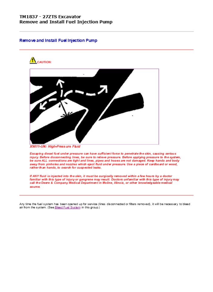
X9811-UN High-Pressure Fluid Escaping diesel
fuel under pressure can have sufficient force to
penetrate the skin, causing serious injury.
Before disconnecting lines, be sure to relieve
pressure. Before applying pressure to the system,
be sure ALL connections are tight and lines,
pipes and hoses are not damaged. Keep hands and
body away from pinholes and nozzles which eject
fluid under pressure. Use a piece of cardboard or
wood, rather than hands, to search for suspected
leaks. If ANY fluid is injected into the skin,
it must be surgically removed within a few hours
by a doctor familiar with this type of injury or
gangrene may result. Doctors unfamiliar with this
type of injury may call the Deere Company
Medical Department in Moline, Illinois, or other
knowledgeable medical source.
Any time the fuel system has been opened up for
service (lines disconnected or filters removed),
it will be necessary to bleed air from the
system. (See Bleed Fuel System in this group.)
2
- 1.
- T123181-UN Injection Pump Injection and Supply
Lines - LEGEND
- - Injection Line
- - Cap Screw (4 used)
- - Hose
- - Clamp
- - Washer (8 used)
- - Supply Line
- Remove fuel injection line (1).
- Remove clamp (4) and hose (3).
- Remove cap screws (2) and washers (5).
- Remove fuel supply line (6).
5. T122388-UN Align Fuel Cut-Off
Lever-to-Governor Cover LEGEND
3
- - Pin
- - Lever
- - Cover
- Align hole of fuel cut-off lever (2) with hole of
governor cover (3) and insert pin (1) into hole.
- 6.
- T122387-UN Center Control Link Pin Groove
- LEGEND
- - Control Link
- - Injection Pump Center Position
- - Pin
- Check to see if pin groove of control link (1) is
at center of injection pump (2). - NOTE
- Mark each pump to aid in assembly. Do not reuse
shim replace with same thickness.
7. T121823-UN Remove and Install Injection
Pump LEGEND
4
https//www.ebooklibonline.com Hello dear
friend! Thank you very much for reading. Enter
the link into your browser. The full manual is
available for immediate download. https//www.ebo
oklibonline.com
5
- - Nut (4 used)
- - Injection Pump
- - Shim
- - Clamp
- Remove nuts (1), injection pump (2), and shim
(3). - NOTE
- For injection pump repair and testing, have an
authorized ADS diesel injection repair station
perform the work. Unauthorized repairs made to
the fuel injection pump will void warranty. - Install new shim (3) with same thickness as
removed. - Install injection pump (2) making sure that rack
pin is in groove of control rack before
tightening injection pump.
Item Measurement Specification
Fuel Injection
Pump Cap Screw Torque 28 N?m (252 lb-ft)
- Remove rack pin from fuel cut-off lever. Confirm
lever moves smoothly. - Install fuel supply line, washers, cap screw and
tighten.
Item
Measurement
Specification
Fuel Injection Fuel Supply Line Cap Screw
Torque
24 N?m (212 lb-in.)
- Install hose and clamp.
- Install fuel injection line and tighten nut.
Item
Measurement
Specification
Fuel Injection
Line Nut
Torque
24 N?m (212 lb-in.)
14. Bleed fuel system. (See procedure in this
group.)
CED,OUOE003,10023-19-19990818
6
TM1837 - 27ZTS Excavator Repair Fuel Injection
Pump
Repair Fuel Injection Pump IMPORTANT Do not
disassemble the fuel injection pump further than
necessary for installing available repair
partsnot even for cleaning. Be sure that all
identification numbers are legible so that pump
is set to the correct specification for its
intended application. For injection pump repair
and testing, have an authorized ADS diesel
injection repair station perform the work.
Unauthorized repairs made to the fuel injection
pumps will void warranty.
CED,OUOE003,10024-19-19990818
7
TM1837 - 27ZTS Excavator Injection Timing Test
and Adjustment
Injection Timing Test and Adjustment
- T123182-UN Remove Valve Holder from Injection
Pump - LEGEND
- - Valve Holder
- - Spring
- - Injection Pump
- Remove fuel injection line from No. 1 cylinder.
- Remove valve holder (1) from injection pump and
remove spring (2). - Install valve holder without spring into
injection pump (3). - Slowly turn crankshaft pulley clockwise. At the
same time continue to feed the fuel. - Stop turning crankshaft when fuel stops flowing
out of No. 1 delivery valve holder. - NOTE
- This crank angle position is the starting point
of injection.
8
- 5.
- T123169-UN Groove Mark and TDC Mark
- LEGEND
- - Groove Mark
- - TDC Mark
- Note position of groove mark (1) on crankshaft
pulley with TDC mark (2) on timing gear case
cover.
Item Measurement Specification
Fuel Injection
Fuel Injection Pump Timing 19 BTDC
- Shim accordingly. Adjust timing with a shim
between injection pump and cylinder block. - Remove valve holder and install spring.
- Install valve holder and fuel injection line.
CED,OUOE003,21117-19-20000111
9
TM1837 - 27ZTS Excavator Remove and Install Fuel
Injection Nozzle
Remove and Install Fuel Injection Nozzle
CAUTION
X9811-UN High-Pressure Fluid Escaping diesel
fuel under pressure can have sufficient force to
penetrate the skin, causing serious injury.
Before disconnecting lines, be sure to relieve
pressure. Before applying pressure to the system,
be sure ALL connections are tight and lines,
pipes and hoses are not damaged. Keep hands and
body away from pinholes and nozzles which eject
fluid under pressure. Use a piece of cardboard or
wood, rather than hands, to search for suspected
leaks. If ANY fluid is injected into the skin,
it must be surgically removed within a few hours
by a doctor familiar with this type of injury or
gangrene may result. Doctors unfamiliar with this
type of injury may call the Deere Company
Medical Department in Moline, Illinois, or other
knowledgeable medical source.
Any time the fuel system has been opened up for
service (lines disconnected or filters removed),
it will be necessary to bleed air from the
system. (See Bleed Fuel System in this
group.) IMPORTANT Before removal, thoroughly
remove all dirt from the cylinder head around
fuel injection nozzles. Clean with compressed air
to prevent dirt from entering the cylinders. Plug
the bore in the cylinder head after each nozzle
has been removed. Cap fuel line openings as soon
as they are disconnected. Do not bend the fuel
delivery lines, as this may affect their
durability. When loosening the fuel pressure
lines, hold male union of nozzle line stationary
with a backup wrench.
10
- 1.
- T123164-UN Remove Fuel Injection and Leak-Off
Line - LEGEND
- - Fuel Injection Line (3 used)
- - Nut (3 used)
- - Nozzle (3 used)
- - Washer (3 used)
- - Fuel Leak-Off Line
- Remove fuel injection line (1) from fuel
injection nozzle and fuel injection pump using a
backup wrench on nozzle connection. - NOTE
- When all fuel injection nozzles have been
removed, disconnect leak-off line and remove as a
complete assembly. For individual nozzle removal,
remove only the section of leak-off line
necessary for nozzle removal. - Remove nut (2) to remove fuel leak-off line (5).
Line must be removed as an assembly. Remove
washer (4). - Remove fuel injection nozzle (3). Protect opening
to avoid contamination.
5.
IMPORTANT
Before installing injection nozzles, make sure
nozzles are clean and free from oil or
grease. NOTE If nozzle bore in cylinder head
must be cleaned, use a nozzle bore cleaning
tool. Install injection nozzles (3) and tighten.
Item Measurement Specification
Fuel Injection
Nozzle-to-Cylinder Head Nut Torque 49 N?m (36 lb-ft)
6. Install washer (4) and leak-off line (5).
Tighten nut (2).
Item Fuel Injection Measurement Specification
Leak-Off Line Nut Torque 34 N?m (301 lb-in.)
11
7. Install fuel injection line (1) using a
backup wrench on nozzle connection.
Item Fuel Injection Measurement Specification
Line Nut Torque 24 N?m (212 lb-in.)
8. Bleed fuel system. (See procedure in this
group.)
CED,OUOE003,21174-19-20000118
12
TM1837 - 27ZTS Excavator Disassemble and Assemble
Fuel Injection Nozzle
Disassemble and Assemble Fuel Injection Nozzle
- T123165-UN Fuel Injection Nozzle
- LEGEND
- - Retaining Nut
- - Injection Nozzle
- - Spring Spacer
- - Push Rod
- - Nozzle Assembly
- - Shim
- - Shim
- - Nozzle Spring
- 1. Disassemble parts (18).
13
2. T113929-UN Check Valve Fit in Body Remove
nozzle assembly from nozzle body. Keep parts
separate to maintain proper needle valve-to-body
combination. 3. Check to see if valve moves
smoothly in body. If not, repair or replace
nozzle.
4. T113930-UN Push Rod Spring Check push rod
spring for wear, weakness, and corrosion.
14
5. T113931-UN Nozzle Holder Push Rod/Needle
Valve Check nozzle holder push rod curvature. 6.
Check nozzle holder push rod and needle valve
contact surfaces for excessive wear and poor
contact.
7. T123166-UN Injection Nozzle Check injection
nozzle needle valve, valve seat and injection
nozzle hole for carbon deposits. If carbon
deposits are present, replace injection nozzle
and needle valve. 8. Hold nozzle body
vertically. Pull needle valve out about one-third
away from nozzle body. Release needle
valve. Check that needle valve falls back into
nozzle body as far as valve seat. If needle
valve does not fall back into nozzle body as far
as valve seat, replace injection nozzle and
needle valve.
9.
NOTE
15
There must be no oil on the contact surfaces of
the injection nozzle and the injection nozzle
holder. Clean these contact surfaces with diesel
fuel before installation. The nozzle dowel pin
must be aligned with the dowel hole in nozzle
holder body.
T113937-UN Align Nozzle Dowel Pin to Holder
Body Install injection nozzle. 10. Install
nozzle holder push rod, push rod spring, and
nozzle adjusting screw.
11. T123168-UN Adjust Pressure Adjust injection
starting pressure using 5-8840-9016-0 nozzle
tester with shims.
Item Fuel Injection Measurement Specification
Nozzle Starting Pressure 13 238 kPa (1920 psi) (132 bar)
16
12. T123167-19 Injector Nozzle Spray
Conditions Check spray condition of injection
nozzle.
CED,OUOE003,10027-19-20000111
17
TM1837 - 27ZTS Excavator Bleed Fuel System
Bleed Fuel System Turn starter switch to the on
position. This will allow the fuel pump to force
feed fuel to the fuel pipe and the lead-off pipe.
Air in the fuel system is automatically bled.
CED,OUOE003,10028-19-19990818
18
TM1837 - 27ZTS Excavator Engine Valve Clearance
Adjustment
- Engine Valve Clearance Adjustment
- Summary
- Perform measurement when engine is cold.
- Before starting work, clean head cover mounting
area to avoid contamination in engine. - Preparation
- 1.
- T123169-UN Align TDC Mark on Crankshaft Pulley
- LEGEND
- - TDC Mark
- - Pointer
- Locate top dead center (TDC) in compression
stroke. - Align TDC (top dead center) mark (1) on
crankshaft pulley with pointer (2) located on
timing gear case as illustrated. Piston No. 1 or
piston No. 3 is now positioned at the TDC in its
compression stroke. - Remove head cover.
- Check for play in the No. 1 intake and exhaust
valve rocker arms. If the No. 1 cylinder intake
and exhaust valve rocker arms have play, No. 1
piston is at TDC on the compression stroke. If
the No. 1 cylinder intake and exhaust valve
rocker arms are depressed, the No. 3 piston is at
TDC on the compression stroke. - Start measurement from cylinder (No. 1 or No. 3)
positioned at TDC in compression stroke. - Measurement
19
T112872-UN Measure Rocker Arm-to-Valve Stem
Clearance 1. Insert a feeler gauge into
clearance between rocker arm and valve stem end
to measure valve clearance. NOTE The cylinders
are aligned from No. 1 to No. 3 in order, as
viewed from the fan side.
2. T127228-19 Valve Arrangement Adjust the
circle or double circle marked valves as shown,
while the No. 1 or No. 3 cylinder is at TDC on
compression stroke. 3. Rotate crankshaft 360.
Align TDC mark with pointer. Then, continue
measurement of other valves in same
way. Evaluation Standard Valve Clearance
Item
Measurement
Specification
Engine Valve Clearance Adjustment
20
Engine Intake and Exhaust Standard Valve
Clearance
0.20 0.05 mm (0.008 0.002 in.) with engine
cold
Place the No. 1 or No. 3 cylinder at TDC by
turning the crankshaft until the TDC mark on the
front cover aligns with the groove mark on the
crankshaft pulley. NOTE If the No. 1 cylinder
intake and exhaust valve rocker arms have play,
the No. 1 piston is at TDC on the compression
stroke. If the No. 1 cylinder intake and exhaust
valve rocker arms are depressed, the No. 3 piston
is at TDC on the compression stroke. Adjustment
- T112872-UN Measure Rocker Arm-to-Valve Stem
Clearance - If the measurement results are out of
specification, adjust the valve clearance in the
same order of measurement. - Loosen adjusting screw lock nuts for rocker arms.
- Insert thickness gauge set at 0.20 mm (0.008
in.). - Adjust adjusting screws until slight drag can be
felt on thickness gauge. - Tighten lock nuts securely.
- Check valve clearance again after lock nuts are
tightened.
Item
Measurement
Specification
Engine Valve Clearance Adjustment
Engine Intake and Exhaust Standard Valve
Clearance
0.20 0.05 mm (0.008 0.002 in.) with engine
cold
CED,OUOE003,21120-19-20000111
21
TM1837 - 27ZTS Excavator Remove and Install
Starter
Remove and Install Starter
- T125137-UN Starter
- LEGEND
- - Electrical Connector
- - Nut
- - Cap Screw
- - Nut
- IMPORTANT
- Always disconnect the negative (-) battery cables
before removing starter or a short circuit could
result. - Disconnect negative (-) battery cables.
- Remove seat. (See procedure in Group 1821.)
- Remove seat base. (See procedure in Group 1821.)
- Disconnect electrical connector (1).
- Remove nut (4). Remove battery cable.
22
Suggest If the above button click is invalid.
Please download this document first, and then
click the above link to download the complete
manual. Thank you so much for reading
23
- Remove cap screw (3).
- Remove nut (2). Remove starter.
- Replace parts as necessary.
- Install starter. Tighten cap screw (3).
Item
Measurement
Specification
Starter
Starter-to-Flywheel Housing Cap Screw
Torque
13 N?m (115 lb-in.)
- Connect wiring leads.
- Connect negative (-) battery cables.
CED,OUOE003,21121-19-20000111
24
https//www.ebooklibonline.com Hello dear
friend! Thank you very much for reading. Enter
the link into your browser. The full manual is
available for immediate download. https//www.ebo
oklibonline.com
Recommended

