
VOLVO EC330C LD EC330CLD EXCAVATOR Service Repair Manual Instant Download PowerPoint PPT Presentation
Title: VOLVO EC330C LD EC330CLD EXCAVATOR Service Repair Manual Instant Download
1
Service Information
Document Title Superstructure, removing Function Group 710 Information Type Service Information Date 2015/4/2 0
Profile EXC, EC330C LD GB Profile EXC, EC330C LD GB Profile EXC, EC330C LD GB Profile EXC, EC330C LD GB
- Superstructure, removing
- Op nbr 710-001
- Park the machine in the service position D. See
091 Service positions. - Position the machine on flat, firm and level
ground, free from any obstructions or
interference. - When the engine is running, the hydraulic line is
under high pressure. Stop the engine, and remove
the residual pressure inside the hydraulic line
by operating the control lever smoothly 3-4
timeswith the ignition key at "ON" position.
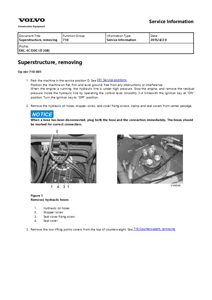
Turn the ignition key to "OFF" position. - Remove the hydraulic oil hoses, stopper screw,
seal cover fixing screws, clamp and seal covers
from center passage.
NOTICE
When a hose has been disconnected, plug both the
hose and the connection immediately. The hoses
should be marked for correct connection.
- Figure 1
- Removal, hydraulic hoses
- Hydraulic oil hoses
- Stopper screw
- Seal cover fixing screw
- Seal cover
- 3. Remove the two lifting points covers from the
top of counterweight. See 716 Counterweight,
removing.
2
Figure 2 Removal, lifting points covers (1)
WARNING
4.
Risk of personal injury. Very heavy object.
WARNING
The parts are heavy. Take appropriate safety
cautions when handling them.
WARNING
Never lift the machine with a person in the cab.
WARNING
Always use classified cables, lifting straps,
shackles and hooks with sufficient lifting
capacity. Hold the superstructure with wire ropes
(cables). Check the superstructure weight. See
710 Machine weight, specifications. Check the
wire ropes length (cables). Refer to the
operators manual for further operation or cab in
lifting machine decal. See Operating
instructions, Transporting machine, Lifting
machine.
- Figure 3
- Lifting superstructure
- Wire rope (cable)
- Superstructure
- Undercarriage
3
Figure 4 Lifting points NOTE! As shown in the
decal for lifting, connect lifting wire ropes
(cables) or slings with sufficient strength for
the machine weight at the lifting points
correctly. After installation of all hoisting
equipment, lift the machine a little to check its
balance, if satisfactory, lift it slowly and
evenly. 5. Remove the superstructure mounting
screws from the swing ring gear.
- Figure 5
- Removal, superstructure mounting screws
- Superstructure mounting screw
- Swing ring gear
WARNING
6.
4
https//www.ebooklibonline.com Hello dear
friend! Thank you very much for reading. Enter
the link into your browser. The full manual is
available for immediate download. https//www.eb
ooklibonline.com
5
The superstructure is heavy. Pay attention to
safe footing and the area around the crane before
proceeding to remove or install the
superstructure. Remove the superstructure slowly
and lower onto the 4 jacks safely. Maintain good
visibility of the machine at all times during the
lift. And continuously check that the machine is
level.
Figure 6 Removal, lifting superstructure (1)
6
Service Information
Document Title Superstructure, installing Function Group 710 Information Type Service Information Date 2015/4/2 0
Profile EXC, EC330C LD GB Profile EXC, EC330C LD GB Profile EXC, EC330C LD GB Profile EXC, EC330C LD GB
Superstructure, installing Op nbr 710-002
WARNING
1.
Risk of personal injury. Very heavy object.
WARNING
The parts are heavy. Take appropriate safety
cautions when handling them.
WARNING
Never lift the machine with a person in the cab.
WARNING
Always use classified cables, lifting straps,
shackles and hooks with sufficient lifting
capacity. Hold the superstructure with wire ropes
(cables). Check the superstructure weight. See
710 Machine weight, specifications. Wire ropes
length (cables). Refer to the operators manual
for further operation or cab in lifting machine
decal. See Operating instructions, Transporting
machine, Lifting machine.
- Figure 1
- Lifting superstructure
- Wire rope (cable)
- Superstructure
- Undercarriage
7
Figure 2 Lifting points NOTE! As shown in the
decal for lifting, connect lifting wire ropes
(cables) or slings with sufficient strength for
the machine weight at the lifting points
correctly. After installation of all hoisting
equipment, lift the machine a little to check its
balance, if satisfactory, lift it slowly and
evenly. 2. Thoroughly clean the mounting
surface. Before replacing the superstructure,
apply sealing compound to the mounting
surface. NOTE! If impurities remain, adhesion
with bond agent is not good.
- Figure 3
- Clean the mounting surface
- Clean the mounting surface
- Sealing compound
8
WARNING
3.
The superstructure is heavy. Pay attention to
safe footing and the area around the crane before
proceeding to remove or install the
superstructure. Lift the superstructure and
install it to the swing ring gear. Maintain good
visibility of the machine at all times during the
lift. And continuously check that the machine is
level. NOTE! Match the S mark (soft zone
position) on inner race and the plug on outer
race.
- Figure 4
- Installation, superstructure
- Superstructure
- Swing ring gear
- S mark inner race (soft zone position)
- Plug outer race
- 4. Install the superstructure mounting screws fro
m the swing ring gear. Tightening torque. See
492 Swing ring gear, description. Apply Loctite
277 or equivalent locking fluid.
Figure 5
9
- Installation, superstructure mounting screws
- Superstructure mounting screw
- Swing ring gear
- 5. Remove the wire rope (cable) at the lifting
points. - Install the seal covers, seal cover fixing
screws, stopper screw, clamp and hydraulic oil
hoses from center passage. Tightening torque,
seal cover fixing screw 22.6 1.96 Nm (2.3 0.2
kgf m) (16.6 1.4 lbf ft) - Apply Loctite 277 or equivalent locking fluid.
- Figure 6
- Installation, hydraulic hoses
- 1. Hydraulic oil hoses
- 2. Stopper screw 242.2 24.5 Nm (24.7 2.5 kgf
m) (178.3 18 lbf ft) - Seal cover fixing screw
- Seal cover
- Stopper screw 15 mm (0.59 inch)
- Install the two lifting points covers from the top
of counterweight. See tightening torque. 716
Counterweight, tightening torques.
Figure 7 Installation, lifting points covers
(1) 7. Check the operation of the swing,
hydraulic oil hoses and swing ring gear mounting
screws.
10
Service Information
Document Title Counterweight, description Function Group 716 Information Type Service Information Date 2015/4/2 0
Profile EXC, EC330C LD GB Profile EXC, EC330C LD GB Profile EXC, EC330C LD GB Profile EXC, EC330C LD GB
Go back to Index Page Counterweight,
description Casting type The counterweight is a
counterbalancing weight that is located at the
rear of the machine. The counterweight is
designed in order to give the machine extra
weight in the back end in order to counter the
weight that is located at the front of the
machine, in particular the boom and dipper arm.
Figure 1 Counterweight, structure
1 Counterweight 6 Shim 11 Screw
2 Cover 7 Lock nut 12 Screw
3 Plate 8 Nut 13 Plug
4 Screw 9 Screw 14 Reflector mounting
5 Spacer 10 Reflector
11
Service Information
Document Title Counterweight, description Function Group 716 Information Type Service Information Date 2015/4/2 0
Profile EXC, EC330C LD GB Profile EXC, EC330C LD GB Profile EXC, EC330C LD GB Profile EXC, EC330C LD GB
Go back to Index Page Counterweight,
description Fabrication type The counterweight is
a counterbalancing weight that is located at the
rear of the machine. The counterweight is
designed in order to give the machine extra
weight in the back end in order to counter the
weight that is located at the front of the
machine, in particular the boom and dipper arm.
Figure 1 Counterweight, structure
1 Body 2 Plate 3 Reflector 4 Cover
5 Stopper 6 Base 7 Side plate 8 Under cover
12
Service Information
Document Title Counterweight, removing Function Group 716 Information Type Service Information Date 2015/4/2 0
Profile EXC, EC330C LD GB Profile EXC, EC330C LD GB Profile EXC, EC330C LD GB Profile EXC, EC330C LD GB
Go back to Index Page Counterweight,
removing Casting type Op nbr 716-001
WARNING
The counterweight is heavy. Take care in
performing removal. To lift the counterweight,
use certified wire ropes in good condition, of
adequate load rating and length.
WARNING
- Heavy lift. Make sure that no persons are under
the counterweight when it is lifted. - Position the machine on flat, firm and level
ground, free from any obstructions or
interference. Position the boom and arm with the
bucket on the ground. - Stop the engine and turn the battery disconnect
switch is off position. - Remove the two covers and plug from the top of
the counterweight. - As shown in the illustration, install each eye
bolt (B), connect lifting cables or slings of
sufficient strength for the counterweight at
each lifting point. - NOTE!
- The rate of the length for lifting cables (A) and
balance cables (C) is 1 0.7.
Figure 1 Attach wire slings A. Lifting cables
13
- Eye bolt
- Balance cable
- 5. Remove the engine room under cover and then
remove screws (9) using socket wrench.
Figure 2 Removal, screws NOTE! Install the
engine room cover after removing
counterweight. 6. Remove lock nut (7) and nut
(8), using socket wrench or power wrench.
Figure 3 Removal, lock nut 7. Lift the
counterweight just a little, and after confirming
safety all around, lift it up and out.
14
Service Information
Document Title Counterweight, removing Function Group 716 Information Type Service Information Date 2015/4/2 0
Profile EXC, EC330C LD GB Profile EXC, EC330C LD GB Profile EXC, EC330C LD GB Profile EXC, EC330C LD GB
Go back to Index Page Counterweight,
removing Fabrication type Op nbr 716-001
WARNING
The counterweight is heavy. Take care in
performing removal. To lift the counterweight,
use certified wire ropes in good condition, of
adequate load rating and length.
WARNING
- Heavy lift. Make sure that no persons are under
the counterweight when it is lifted. - Position the machine on flat, firm and level
ground, free from any obstructions or
interference. Position the boom and arm with the
bucket on the ground. - Place the machine in the Service position B. see
091 Service positions. - Remove the plugs on the top surface of the
counterweight and install eye bolts (2) - Attach wire slings (1) to eye bolts (2) and lift
until there is no slack in the wire ropes. - NOTE!
- Recommendation length of wire slings to keep
counterweight level. - A 2100 mm (82.7 inch), B 2050 mm (80.7 inch)
Figure 1
15
- Remove the engine room under cover then remove
screw (7), spring washer (8) and plain washer
(9). - Remove screw (6), spacer (5).
- Lift the counterweight just a little, and after
confirming safety all around, lift it up and out. - Remove the counterweight and securely support the
counterweight. - Install the engine room under cover.
16
Service Information
Document Title Counterweight, fitting Function Group 716 Information Type Service Information Date 2015/4/2 0
Profile EXC, EC330C LD GB Profile EXC, EC330C LD GB Profile EXC, EC330C LD GB Profile EXC, EC330C LD GB
Go back to Index Page Counterweight,
fitting Casting type Op nbr 716-002
WARNING
Lift the counterweight just a little, and after
confirming safety and horizontal position,
proceed to install it.
WARNING
- Heavy lift. Make sure that no persons are under
the counterweight when it is lifted. - Position the machine on flat, firm and level
ground, free from any obstructions or
interference. Position the boom and arm with the
bucket on the ground. - Attach wire slings to the lifting eyes at the top
surface of the counterweight and lift to the
desired position. - NOTE!
- The ratio of the length for lifting cables (A)
and balance cables (C) is 1 0.7.
- Figure 1
- Installation, counterweight
- Lifting cables
- Eye bolt
- Balance cable
- 3. Tighten nut (8) to the specified torque and
then tighten lock nut (7). - NOTE!
- Apply loctite 277 on threads of screws (4).
17
NOTE! Maintain the clearance (left and right)
within 7 - 13 mm.
Figure 2 Tightening, lock nut 4. Remove the
engine room under cover and match the screws
hole. and then install and tighten screws (9) to
the specified torque. See tightening torque, 716
Counterweight, tightening torques. NOTE! Apply
loctite 277 on threads of screws (9).
- Figure 3 Tightening, screws
- install the engine room under cover.
- Install the two covers and remove the eye bolts.
Assemble the plug to the top of counterweight.
18
Service Information
Document Title Counterweight, fitting Function Group 716 Information Type Service Information Date 2015/4/2 0
Profile EXC, EC330C LD GB Profile EXC, EC330C LD GB Profile EXC, EC330C LD GB Profile EXC, EC330C LD GB
Go back to Index Page Counterweight,
fitting Fabrication type Op nbr 716-002
WARNING
Lift the counterweight just a little, and after
confirming safety and horizontal position,
proceed to install it. 1. Position the machine
on flat, firm and level ground, free from any
obstructions or interference. Position the boom
and arm with the bucket on the ground. Place the
machine in the Service position B. see 091
Service positions.
- Figure 1
- Engage the control lockout lever securely.
- Clean the surfaces of counterweight mounting
before fitting. - Remove the engine room under cover.
- NOTE!
- Recommendation length of wire slings to keep
counterweight level. - A 2100 mm (82.7 inch), B 2050 mm (80.7 inch)
- Lower the counterweight to the mounting face at
the rear of the superstructure.
19
- Match the screw hole. Insert spacer (5) and
tighten mounting screw (6). - NOTE!
- Coat the screws with "Loctite 277"
- Install plain washer (9), spring washer (8) and
tighten screw (7) then install engine room under
cover. - NOTE!
- Coat the screws with "Loctite 277"
- Remove the eye bolts and install the plugs.
- Tightening torque
No. Specifications
Screw (6) 1900 190 Nm (193 19 kgf m) (1394 137 lbf ft)
Screw (7) 885 88 Nm (90.2 9 kgf m) (651 65 lbf ft)
NOTE! Keep Top, bottom, left and right clearance
to be equal. (A 1015mm, 0.40.6 in)
Figure 2
20
Service Information
Document Title Undercarriage, description Function Group Information Type Service Information Date 2015/4/2 0
Profile EXC, EC330C LD GB Profile EXC, EC330C LD GB Profile EXC, EC330C LD GB Profile EXC, EC330C LD GB
Undercarriage, description Undercarriage consists
of idlers, recoil springs, top and bottom
rollers, sprockets, track links, track frame and
track guards.
Figure 1 Structure, undercarriage
1 Idler 4 Track frame 7 Track guard
2 Recoil spring 5 Sprocket 8 Track link
3 Top roller 6 Bottom roller
21
Service Information
Document Title Selection of track shoes Function Group 775 Information Type Service Information Date 2015/4/2 0
Profile EXC, EC330C LD GB Profile EXC, EC330C LD GB Profile EXC, EC330C LD GB Profile EXC, EC330C LD GB
Selection of track shoes Choose suitable track
shoes to match the ground conditions. Method of
selecting shoes Confirm the category from the
list of uses in the "Category" table then use the
"Selection" table to select the shoe. Categories
B and C are wide shoe, so there are
restrictions on their use.Therefore, before
using, check the restrictions and consider
carefully the conditions of use before selecting
a suitable shoe width. If necessary, give the
customer guidance in their use. When selecting
the shoe width, select the narrowest possible
within the range that will give no problem with
flotation and ground pressure. If a wider shoe
than necessary is used, there will be a large
load on the shoe, and this may lead to bending
of the shoe, cracking of the links, breakage of
the pins, loosening of the shoe screws, or other
problems. Category, track shoes
Category Use Precautions when using
A Rocky ground, normal soil Travel in low speed when traveling on rough ground with obstacles such as large boulders and fallen trees.
B Soft ground Travel in high speed only on flat ground. When it is impossible to avoid traveling over obstacles, lower the travel speed to approximate half of low speed. NOTE! Cannot be used on rough ground where there are large obstacles such as boulders and fallen trees.
C Extremely soft ground (swamp ground) Use only for ground where A and B are impossible to use. Travel in high speed only on flat ground. When it is impossible to avoid traveling over obstacles, lower the travel speed to approximate half of low speed. NOTE! Cannot be used on rough ground where there are large obstacles such as boulders and fallen trees.
Selection, track shoes
Specifications Category
600 mm grouser A
700, 800 mm grouser B
900 mm grouser C
600 mm double grouser A
22
Suggest For more complete manuals. Please go to
the home page. https//www.ebooklibonline.com If
the above button click is invalid. Please
download this document first, and then click the
above link to download the complete
manual. Thank you so much for reading
23
Service Information
Document Title Idler, description Function Group Information Type Service Information Date 2015/4/2 0
Profile EXC, EC330C LD GB Profile EXC, EC330C LD GB Profile EXC, EC330C LD GB Profile EXC, EC330C LD GB
Go back to Index Page
Idler, description
- Figure 1 Structure, idler
- Idler wheel
- Shaft
- Bushing
- Support
- Seal ring
- O-ring
- Pin
- Plug
- O-ring (Shaft)
24
Service Information
Document Title Idler, description Function Group Information Type Service Information Date 2015/4/2 0
Profile EXC, EC330C LD GB Profile EXC, EC330C LD GB Profile EXC, EC330C LD GB Profile EXC, EC330C LD GB
Go back to Index Page
Idler, description
- Figure 1 Structure, idler
- Idler wheel
- Shaft
- Bushing
- Support
- Seal ring
- O-ring
- Pin
- Plug
- O-ring (Shaft)
25
https//www.ebooklibonline.com Hello dear
friend! Thank you very much for reading. Enter
the link into your browser. The full manual is
available for immediate download. https//www.eb
ooklibonline.com
Recommended
