
YALE (A974) GLP050LX, GDP050LX LIFT TRUCK Service Repair Manual Instant Download
Title:
YALE (A974) GLP050LX, GDP050LX LIFT TRUCK Service Repair Manual Instant Download
Description:
YALE (A974) GLP050LX, GDP050LX LIFT TRUCK Service Repair Manual Instant Download –
Number of Views:0
Title: YALE (A974) GLP050LX, GDP050LX LIFT TRUCK Service Repair Manual Instant Download
1
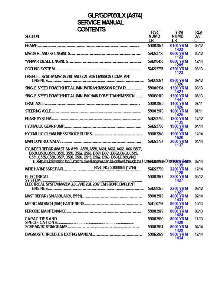
GLP/GDP050LX (A974) SERVICE MANUAL CONTENTS
SECTION PART NUMBER YRM NUMBER REV DATE
FRAME............................................................................................................................ 550013974 0100 YRM 1423 03/12
MAZDA FE AND F2 ENGINES....................................................................................... 524223756 0600 YRM 1122 03/12
YANMAR DIESEL ENGINES.......................................................................................... 524240453 0600 YRM 1205 12/14
COOLING SYSTEM........................................................................................................ 524223757 0700 YRM 1123 03/13
LPG FUEL SYSTEM MAZDA 2.0L AND 2.2L 2007 EMISSION COMPLIANT
ENGINES.................................................................................................................... 524289374 0900 YRM 1326 09/12
SINGLE SPEED POWERSHIFT ALUMINUM TRANSMISSION REPAIR..................... 550010194 1300 YRM 1421 08/13
SINGLE SPEED POWERSHIFT ALUMINUM CHAIN DRIVE TRANSMISSION............ 550030170 1300 YRM 1447 08/13
DRIVE AXLE................................................................................................................... 550013975 1400 YRM 1426 07/11
STEERING AXLE............................................................................................................ 550013976 1600 YRM 1425 07/11
BRAKE SYSTEM............................................................................................................ 524223765 1800 YRM 1135 12/12
HYDRAULIC GEAR PUMP............................................................................................. 524223766 1900 YRM 1136 04/14
HYDRAULIC CLEANLINESS PROCEDURES............................................................... 550073240 1900 YRM 1620 12/14
MAIN CONTROL VALVE................................................................................................ 524223767 2000 YRM 1137 04/14
CYLINDER REPAIR (MAST S/N A551, A555, A559, A661, A662, A663, A66, B507,
B508, B509, B551, B555, B559, B562, B563, B564, B661, B662, B663, C515,
C551, C555, C559, D507, D508, D509, D515, D562, D563, D564, E509, AND
E564).......................................................................................................................... 524223768 2100 YRM 1139 02/14
WIRE HARNESS REPAIR.............................................................................................. 524223769 2200 YRM 1128 12/14
ELECTRICAL SYSTEM.................................................................................................. 550013977 2200 YRM 1427 03/12
ELECTRICAL SYSTEM MAZDA 2.0L AND 2.2L 2007 EMISSION COMPLIANT
ENGINES.................................................................................................................... 524289375 2200 YRM 1327 09/12
MAST REPAIR (S/N A698, A699, B551)........................................................................ 550013978 4000 YRM 1431 02/14
METRIC AND INCH (SAE) FASTENERS....................................................................... 524150797 8000 YRM 0231 10/13
PERIODIC MAINTENANCE............................................................................................ 550013979 8000 YRM 1424 08/13
CAPACITIES AND SPECIFICATIONS........................................................................... 550013980 8000 YRM 1428 11/13
SCHEMATICS/DIAGRAMS............................................................................................ 550013981 8000 YRM 1429 04/14
DIAGNOSTIC TROUBLESHOOTING MANUAL............................................................ 550022929 9000 YRM 1434 12/14
Service information for Cummins diesel engines
can be ordered through the Hyster Literature
Distribution Center. PART NO. 550038069 (12/14)
2
100 YRM 1423
General
General The surface must be solid, even, and
level when the
WARNING
lift truck is put on blocks. Make sure that any
blocks used to support the lift truck are solid,
one-piece units. See the Operating Manual or the
section Pe- riodic Maintenance 8000 YRM
1424. This section contains the description of
the frame (see Figure 1) and connected parts.
Procedures for remov- ing and installing the
counterweight, hood, overhead guard, engine, and
cooling system are found in this sec- tion.
Checks for the operator restraint system, adjust-
ments for the throttle pedal stop, and
procedures for the repair of tanks and
installation of safety labels are also included.
- The lift truck must be put on blocks for some
types of maintenance and repairs. The removal of
the following assemblies will cause large
changes in the center of gravity mast, drive
axle, engine and transmission, and
counterweight. When the lift truck is put on
blocks, put additional blocks in the following
positions to maintain stability - Before removing the mast and drive axle, put
blocks under the counterweight so the lift truck
cannot fall backward. - Before removing the counterweight, put blocks
under the mast assembly so the lift truck cannot
fall forward.
- COWL PLATE
- FENDER
- FRAME
- HOOD MOUNT
- COUNTERWEIGHT SUPPORT
- LEFT-HAND FRAME WELDMENT
- HYDRAULIC TANK
Figure 1. Frame
1
3
Hood, Seat, and Side Covers Replacement
100 YRM 1423
Hood, Seat, and Side Covers Replacement
- REMOVE
- Slide the seat to the closest position to the
steering column. - Fully tilt the steering column forward.
- NOTE Perform Step 3 for lift trucks equipped
with LPG.
8. Fully lower the steering column.
- Swing LPG tank off to side. See LPG Fuel System,
Mazda FE and F2 Emission Compliant Engines 900
YRM 1326 for procedures. - Raise the hood latch on the left, front corner of
the hood to unlatch and lift up the hood. See
Figure 2. - Remove the floor mat and floor plate. See Figure
3. - Remove the two capscrews holding the left and
right rear side covers to the frame. Remove the
rear side covers from the frame. See Figure 3. - Remove the four capscrews and clip nuts holding
the left and right front side covers and left and
right cowl plates to the frame. Remove front
side covers and cowl plates.
- HOOD LATCH 3. HOOD
- SEAT
- Figure 2. Hood Latch
- Legend for Figure 3
- LEFT REAR SIDE COVER
- RIGHT REAR SIDE COVER
- FLOOR MAT
- FLOOR PLATE
- RADIATOR COVER
- SEALS
- CAPSCREW
- CLIP NUT
- INSERT
- PLATE ASSEMBLY SEAL
- LEFT COWL PLATE
- RIGHT COWL PLATE
- DASH ASSEMBLY
- UPPER STEERING COLUMN COVER
- LOWER STEERING COLUMN COVER
- KICK PANEL
- PLATE ASSEMBLY
- GROMMET
- LEFT FRONT SIDE COVER
- RIGHT FRONT SIDE COVER
9. LEFT STEP PANEL
10. RIGHT STEP PANEL
- LEFT STEP PLATE
- RIGHT STEP PLATE
2
4
https//www.ebooklibonline.com Hello dear
friend! Thank you very much for reading. Enter
the link into your browser. The full manual is
available for immediate download. https//www.eb
ooklibonline.com
5
100 YRM 1423
Hood, Seat, and Side Covers Replacement
Figure 3. Side Cover, Floor Plate, and Cowl
Components
3
6
Hood, Seat, and Side Covers Replacement
100 YRM 1423
- Remove upper steering column cover by pulling up
on the base of the upper steering column cover to
release the latches (one on either side), and
pulling cover away from steering column. See
Figure 4. - Remove the five Allen Head screws (see Figure 4)
securing the dash to top of cowl.
- Pull kick panel up from bottom and out to remove
kick panel from seal plate and clips on dash
panel. - Remove dash panel from cowl. See Figure 5.
- Remove three capscrews holding the seal plate.
Remove seal plate. See Figure 5.
- NOTE TOP VIEW OF DASH PANEL SHOWN
- INDICATES TO PULL UP TO UNLATCH
- ALLEN HEAD SCREWS
- COWL
- UPPER STEERING COLUMN COVER
- LOWER STEERING COLUMN COVER
Figure 4. Dash Panel and Upper Steering Column
Cover Removal
4
7
100 YRM 1423
Hood, Seat, and Side Covers Replacement
- ALLEN HEAD SCREWS
- COWL
- DASH PANEL
- KICK PANEL
- KICK PANEL NOTCHES
- SEAL PLATE
- CAPSCREWS
- CLIPS
Figure 5. Dash Panel, Kick Panel, and Seal Plate
Removal
5
8
Hood, Seat, and Side Covers Replacement
100 YRM 1423
14. Remove two capscrews and washers from cover
plate and remove electrical cover. Disconnect
seat harness from chassis harness. See Figure 6.
- and nuts holding the seat to the hood. Lift the
seat off the hood. See Figure 7. Close hood. - Remove the nuts from ball studs on gas springs.
Remove gas springs from the hood. See Figure 8. - Remove the hinge capscrews and nuts, located in
the rear of the hood. See Figure 8. - Lift the hood from the truck.
CAUTION When removing the seat from the hood, do
not use an impact wrench to remove the
capscrews. Dam- age can be caused to the threads
on the capscrews and in the holes. 15. Open hood
and pull chassis harness through hole in hood.
See Figure 7. Remove the four capscrews
- NON-SUSPENSION SEAT
- CAPSCREWS
- WASHER
- COVER PLATE
- B. FULL SUSPENSION SEAT
- ELECTRICAL CONNECTOR (SEAT HARNESS)
- ELECTRICAL COVER
Figure 6. Disconnect Seat Wire Harness
6
9
100 YRM 1423
Hood, Seat, and Side Covers Replacement
- Legend for Figure 7
- NOTE MOUNTING HOLES FOR FULL SUSPENSION SEAT
SHOWN. MOUNTING HOLES FOR NON-SUS- PENSION SEAT
ARE THE SAME. - CAPSCREW
- NUT
- HOLE FOR CHASSIS HARNESS
- HOOD LINER
Figure 7. Remove Seat From Hood
A. HOOD HINGE ARRANGEMENT B. GAS SPRING ARRANGEMENT (LEFT SIDE SHOWN)
1. NUT 6. BALL STUD
2. CAPSCREW 7. GAS SPRING MOUNTING BRACKET
3. HOOD HINGE MOUNT 8. HOOD MOUNT
4. HOOD HINGE ARM 9. GAS SPRING
5. HOOD
Figure 8. Gas Spring and Hood Removal
7
10
Hood, Seat, and Side Covers Replacement
100 YRM 1423
INSTALL
(two clicks). Also check that hood touches rubber
bumper. If necessary, repeat Step 4 and Step 5.
- Place the hood onto the lift truck frame.
- Install the hood hinge mount screws and nuts, lo-
cated in the rear of the hood, and tighten to 38
Nm (28 lbf ft). See Figure 8. - Align the ball studs in the gas springs with
holes in the gas spring mounting bracket and
hood mount. See Figure 9 for holes to use
depending on type of seat being installed.
Install nuts on ball studs to attach gas springs
to the hood. Tighten nuts to - 19.2 Nm (170 lbf in).
- Install latch striker in highest slot position.
Check that latch striker is in center of jaws of
hood latch when hood closes. Open and close the
hood to en- sure that the center pin strikes the
hood latch prop- erly and that the stop screw
contacts the frame. A properly closed hood MUST
click twice on the hood latch. If the hood latch
does not close properly, loosen the capscrews on
the back of the center pin and adjust the center
pin up or down as required for correct
alignment. See Figure 10. - Push down until hood just touches rubber bumper.
Make sure latch striker is still in center of
hood latch. Open hood and tighten capscrews for
latch. - Check operation of hood latch. Have an opera-
tor sit in the seat. Make sure hood is fully
closed
CAUTION When installing the seat to the hood, do
not use an impact wrench to install the
capscrews. Damage can be caused to the threads
on the screws and in the holes.
- Place the seat on the hood and thread the chassis
harness through the holes in the hood. See Fig-
ure 7. - Align the holes in the seat with the holes in the
hood. See Figure 7. Insert capscrews and nuts.
Tighten capscrews to 18 Nm (159 lbf in). - Connect seat harness to chassis harness. Install
cover plate to electrical cover using two
capscrews and washers. See Figure 6.
- Using three capscrews, install seal plate. See
Fig- ure 5. Tighten capscrews to 10.8 Nm (95.6
lbf in). - Place dash panel on cowl and secure dash panel
to cowl using five Allen Head screws. Tighten
Allen Head screws to 3.5 Nm (31 lbf in). See
Figure 4. - Align notches on kick panel to clips on dash
panel and push kick panel into place on seal
plate. See Figure 5.
- LEFT SIDE
- FULL SUSPENSION SEAT
- NON-SUSPENSION SEAT
- B. RIGHT SIDE
- GAS SPRING MOUNTING BRACKET
- HOOD MOUNT
- Figure 9. Gas Spring and Seat Hole Alignment
8
11
100 YRM 1423
Hood, Seat, and Side Covers Replacement
- NOTE Perform Step 17 for lift trucks equipped
with LPG. - Swing the LPG tank into position on back of coun-
terweight. See LPG Fuel System, Mazda FE and F2
Emission Compliant Engines 900 YRM 1326 for
procedures. - Adjust the steering column and seat positions.
- BELLY PAN (OPTIONAL)
- Remove
- Remove four capscrews and four nuts from belly
pan and frame. See Figure 11. - Remove belly pan from frame. See Figure 11.
- Clean and Inspect
- Remove debris from belly pan and inspect for
damage. Replace if necessary. - Install
- Slide belly pan into position on frame. See Fig-
ure 11. - Install four capscrews and four nuts onto belly
pan and frame. See Figure 11.
- HOOD
- HOOD LATCH
- CENTER PIN
- CAPSCREW
- Figure 10. Hood Latch Adjustment
- Raise steering column to highest position and in-
stall upper steering column cover by aligning
the two latches and pushing down until latched.
See Figure 4. - Using four capscrews and clip nuts, install the
left and right front side covers and left and
right cowl plates to the frame. See Figure 3. - Using two capscrews, install the left and right
rear side covers to the frame. See Figure 3. - Install the floor mat and floor plate.
- BELLY PAN
- CAPSCREW
- NUT
- FRAME
Figure 11. Belly Pan
9
12
Steering Column
100 YRM 1423
Steering Column
DESCRIPTION This section describes the repair
procedures for the steering column. The Steering
Column Assembly mounts to the cowl inside the
operator compartment and is the mechanical
connection between the steering
2. Attach a tag on the battery connector or nega-
tive battery cable stating, DO NOT CONNECT
BATTERY. Move the steering column to the most
FORWARD position.
CAUTION If a puller tool is used to remove
steering wheel from steering column, be careful
not to damage horn wires. NOTE This procedure
is for the removal of all compo- nents of the
steering column assembly. All components are not
often removed for a repair procedure. Do only
those steps of the procedure necessary to remove
the required component. NOTE Tag wires prior to
disconnect
wheel and the steering control unit. The steering
col- umn includes the steering wheel, housing,
bracket and lower shaft. For lift trucks with
gas and LPG engines, bolts and bushings attach
the steering column to the cowl standoffs. For
lift trucks with diesel engines, bolts, bushings
and isolators attach the steering column to the
cowl standoffs See Figure 12. STEERING COLUMN
REPAIR Remove 1. Put blocks on each side (front
and back) of tires to prevent lift truck from
moving.
- Remove the horn button assembly and disconnect
electrical wires. Remove large hex nut and
steering wheel from steering column. See Figure
13. - Remove steering column covers. Remove floor mats
and floor plate. See section Hood, Seat, and
Side Covers Replacement.
CAUTION Disconnect the negative battery cable on
internal combustion trucks. Disconnect the
battery before removing any covers.
NOTE Perform Step 5 for lift trucks equipped
with gas or LPG engines. 5. Remove four
capscrews, four bushings and steer- ing column
from cowl standoffs. See Figure 14.
NOTE DIESEL SHOWN, LPG AND GAS SIMILAR.
- STEERING WHEEL
- STEERING COLUMN
- COWL
- Figure 12. Steering Column and Cowl
- HORN BUTTON
- HEX NUT
- STEERING WHEEL
4. STEERING COLUMN
Figure 13. Steering Wheel Remove/Install
10
13
100 YRM 1423
Steering Column
NOTE Perform Step 6 for lift trucks equipped
with diesel engines. 6. Remove four capscrews,
four bushings, four isola- tors, steering column
and four isolators from cowl standoffs. See
Figure 14.
- See Figure 16
- For lift trucks manufactured after January, 2012
- Remove split pin and lower shaft from upper
shaft. See Figure 15 - For lift trucks manufactured before January, 2012
- See Figure 16
- For lift trucks manufactured after January, 2012
- Remove connector from connector bracket. Re-
move connector bracket, fastener, four screws and
two horn contacts from housing. - See Figure 15
- For lift trucks manufactured before January, 2012
- See Figure 16
- For lift trucks manufactured after January, 2012
Disassemble NOTE Remove and discard snap rings
if installed.
- Remove two pins and gas spring from housing.
- See Figure 15
- For lift trucks manufactured before January, 2012
- See Figure 16
- For lift trucks manufactured after January, 2012
- Remove two pivot bolts, two bushings, two nuts
and bracket from housing. - See Figure 15
- For lift trucks manufactured before January, 2012
NOTE DIESEL SHOWN, LPG AND GAS SIMILAR.
- CAPSCREW
- BUSHING
- ISOLATOR
- STEERING COLUMN
- COWL STANDOFF
Figure 14. Steering Column Remove/Install
11
14
Steering Column
100 YRM 1423
Figure 15. Steering Column Assembly, Lift Trucks
Manufactured Before January, 2012
12
15
100 YRM 1423
Steering Column
- Legend for Figure 15
- CONNECTOR BRACKET
- PIVOT BOLT
- BUSHING
- NUT
- GAS SPRING
- BRACKET
- CONNECTOR
- PIN
- LOWER SHAFT
- SPLIT PIN
- UPPER SHAFT
- HOUSING
- HORN CONTACT
- SCREW
- FASTENER
- BRACKET
- SPACER
- JOINT
- NUT
- WASHER
- SCREW
- UPPER SHAFT
- HOUSING
- PIN
- LOWER SHAFT
- GAS SPRING
- BOLT
- BUSHING
- CONNECTOR
- FASTENER
- HORN CONTACT
Figure 16. Steering Column Assembly, Lift Trucks
Manufactured After January, 2012
13
16
Steering Column
100 YRM 1423
Clean
- Assemble lower shaft and upper shaft, secure with
spit pin. - See Figure 15
- For lift trucks manufactured before January, 2012
- See Figure 16
- For lift trucks manufactured after January, 2012
- Install two pivot bolts, two bushings, two nuts
and bracket onto housing. - See Figure 15
- For lift trucks manufactured before January, 2012
- See Figure 16
- For lift trucks manufactured after January, 2012
- Install gas spring and two pins on housing. See
Figure 15 - For lift trucks manufactured before January, 2012
- See Figure 16
- For lift trucks manufactured after January, 2012
WARNING Cleaning solvents can be flammable and
toxic and can cause skin irritation. When using
cleaning solvents, always follow the solvent
manufacturers recommended safety precautions.
- WARNING
- Compressed air is used for cleaning and drying
pur- poses, or for cleaning restrictions. wear
protective clothing (goggles/shields, gloves,
etc.). Make sure the path of the compressed air
is away from all per- sonnel to avoid injury. - Clean metal parts in solvent. Remove all traces
of old lubricant and dirt. Clean nonmetal parts
with warm soapy water and a lint free cloth. - After cleaning dry parts with compressed air. DO
NOT dry parts with a cloth. - Inspect
Install NOTE Lubricate spline end of lower shaft
with multi purpose grease, see Periodic
Maintenance Manual for your lift truck. NOTE
Perform Step 1 for lift trucks equipped with gas
or LPG engines. 1. Install steering column, four
bushings and four bolts on cowl standoffs.
Tighten bolts to 38 Nm (28 lbf ft). See Figure
14. NOTE Perform Step 2 for lift trucks equipped
with diesel engines.
- Inspect for loose, burned, missing, cracked or
dam- aged hardware. - Inspect all parts for dents, holes, bends, burrs,
rust, corrosion or marred finishes. - Replace all defective or damaged parts.
- Assemble
- NOTE This procedure is for the installation of
all com- ponents of the steering column
assembly. All compo- nents are not often removed
for a repair procedure. Do only those steps of
the procedure necessary to install the required
component. - NOTE Perform Step 1 only for lift trucks
manufactured before January, 2012. - Lubricate the horn contact slip rings with a
small amount of conductive grease Yale P/N
582014302. See Figure 15. - Install fastener, connector bracket and
connector, two horn contacts and four screws. - See Figure 15
- For lift trucks manufactured before January, 2012
- See Figure 16
- For lift trucks manufactured after January, 2012
- Install four isolators, steering column four
isolators, four bushings and four bolts
standoffs on cowl. Tighten bolts to 38 Nm (28
lbf ft). See Figure 14. - Install floor plate, floor mats and steering
column covers. See section Hood, Seat, and Side
Covers Replacement. - Install steering wheel and hex nut on steering
column. Tighten hex nut to 40 to 54 Nm (30 to
40 lbf ft). Connect electrical wiring and install
horn button. See Figure 13. - Remove tag from negative battery connector and
connect to battery. Adjust steering column to
neu- tral position.
14
17
100 YRM 1423
Counterweight Replacement
6. Remove blocks from each side of tires.
Counterweight Replacement from the LPG tank where
it enters the filter unit. Permit the pressure
in the fuel system to decrease slowly. Fuel
leaving the fitting removes heat. Use a
REMOVE
WARNING
cloth to protect your hands from the cold
fitting. NOTE The counterweight is held in
position on the frame by two hooks that are part
of the frame. One M24 3 110 capscrew holds
the counterweight to the lower part of the frame
on lift truck models See Figure 17. NOTE Perform
Step1 for lift trucks equipped with LPG.
- The lift truck must be put on blocks for some
types of maintenance and repair. The removal of
the following assemblies will cause large
changes in the center of gravity mast, drive
axle, engine and transmission, and
counterweight. When the lift truck is put on
blocks, put additional blocks in the following
positions to maintain stability - Before removing the mast and drive axle, put
blocks under the counterweight so the lift truck
cannot fall backward. - Before removing the counterweight, put blocks
under the mast assembly so the lift truck cannot
fall forward. - The surface must be solid, even, and level when
the lift truck is put on blocks. Make sure that
any blocks used to support the lift truck are
solid, one-piece units. See the Operating Manual
or the section Pe- riodic Maintenance 8000 SRM
1424.
1. Use the procedures in LPG Fuel System, Mazda
FE and F2 Emission Compliant Engines 900 YRM
1326 to remove the LPG tank and bracket so that
the counterweight can be removed. Additional
information on the LPG fuel system can be found
in LPG Fuel System, Mazda FE and F2 Emission
Compliant Engines 900 YRM 1326.
WARNING The counterweight is heavy. Make sure
that the eye- bolts and lifting devices have
enough capacity to lift the weight. The
approximate weights of the coun- terweight
castings are shown in Table 1.
WARNING DO NOT operate the lift truck if the
capscrew for the counterweight is not installed.
When the capscrew is removed, the counterweight
can fall from the lift truck.
- Install washers, lifting eyebolts, and nuts into
lift holes of the counterweight. See Figure 18.
Con- nect a crane to the lifting eyebolts and
raise the crane until it holds part of the
weight of the coun- terweight. - Remove the tow pin from counterweight.
- Remove the capscrew from counterweight and
frame. See Figure 17 and Figure 18. Use the
crane to lift the counterweight from the lift
truck. Put counterweight on the floor so that it
has stabil- ity and will not fall over. Take
care not to damage exhaust or cooling system
components.
WARNING LPG can cause an explosion. DO NOT cause
sparks or permit flammable material near the LPG
system. LPG fuel systems can be disconnected
indoors only if the lift truck is at least 8 m
(26 ft) from any open flame, motor vehicles,
electrical equipment, or ignition source. Close
the shutoff valve on the LPG tank before any
part of the engine fuel system is disconnected.
Run the engine until the fuel in the system is
used and the engine stops. If the engine will
not run, close the shutoff valve on the LPG
tank. Loosen the fitting on the supply hose
15
18
Counterweight Replacement
100 YRM 1423
- TOW PIN
- CAPSCREW
- LOCKWASHER
- WASHER
- FRAME
- SEAL
Figure 17. Counterweight Installation Table 1.
Weight of Counterweights
- SEAL
- COUNTERWEIGHT
- LIFT HOLE
- TOW PIN
- CAPSCREW
- LOCKWASHER
- WASHER
- LPG ACCESS HOLE
Model kg lb
GLC050LX (A967) 1401 3088
GLP/GDP20LX (A974) 950 2094
GLP/GDP25LX (GLP/GDP050LX) (A974) 1230 2712
GLP/GDP25LX (GLP/GDP050LX) (A974) 1335 2943
9. LIFTING EYEBOLT
10. NUT Figure 18. Counterweight With Lifting
Eyebolts
16
19
100 YRM 1423
Overhead Guard Replacement
- INSTALL
- Make sure the seals are on the counterweight. If
lift- ing eyebolts were removed from
counterweight, in- stall washers, lifting
eyebolts, and nuts into lift holes on
counterweight. See Figure 18. - Connect a crane to the lifting eyebolts and place
counterweight in position on lift truck frame.
Make sure hooks on frame fully engage
counterweight so it is aligned with the frame.
- Install capscrew onto counterweight and frame.
See Figure 17 and Figure 18. Tighten capscrew to
555 Nm (409 lbf ft). - Install tow pin onto counterweight.
- NOTE Perform Step5 for lift trucks equipped with
LPG. - Use the procedures in LPG Fuel System, Mazda FE
and F2 Emission Compliant Engines 900 YRM 1326
to install the LPG tank and bracket after the
counterweight has been installed.
Overhead Guard Replacement
REMOVE
3. Remove capscrews from overhead guard rear legs
and frame. See Figure 19.
WARNING DO NOT operate the lift truck without the
overhead guard correctly fastened to the lift
truck. WARNING DO NOT weld mounts for lights or
accessories to legs of the overhead guard.
Changes that are made by welding, or by drilling
holes that are too big or in the wrong location,
can reduce the strength of the overhead
guard. See your dealer for Yale lift trucks
BEFORE perform- ing any changes to the overhead
guard. NOTE The lifting device can be connected
to any num- ber of positions on the overhead
guard depending upon the lifting device
available. The ideal choices are a four point
sling connected to all four corners on the top of
the overhead guard, or a two point sling
connected to two opposite corners of the
overhead guard. If a sin- gle point hoist is
used, make sure that the lift point is as close
to the center of the overhead guard as possible.
If during the initial start of the lift, the
overhead guard is off balance, lower immediately
and move the hoist to a more centered point.
- No welding or drilling on legs of overhead guard
is per- mitted as per previous WARNING. - Connect a lifting device to overhead guard.
- NOTE Note routing of electrical wires prior to
discon- necting. Tag electrical connectors
during removal to aid in installation. - Disconnect wires between frame and overhead
guard.
- OVERHEAD GUARD REAR LEG
- CAPSCREW
- FRAME
- OVERHEAD GUARD FRONT LEG
- HANDLE
- Figure 19. Overhead Guard
17
20
Overhead Guard Replacement
100 YRM 1423
- Remove dash and kick panel from cowl. See Hood,
Seat, and Side Covers Replacement for removal
procedures. - Remove capscrews from overhead guard front legs
and frame. See Figure 19. - NOTE When overhead guard is lifted from the
frame, make sure that any electrical wires are
moved through the holes in the frame so that
they are not damaged. - Using lifting device, remove overhead guard from
frame. See Figure 19. - Remove capscrews and handle from overhead guard.
See Figure 19.
- Remove two capscrews, two wheel nuts and two
brackets from front center of overhead guard. See
Figure 20. - Remove two capscrews, two wheel nuts, right
bracket and left bracket from front corner of
over- head guard. See Figure 20. - NOTE Note position of rain top on overhead guard
be- fore removal. - Remove rain top from overhead guard. See Fig-
ure 20. - Clean and Inspect
- Clean all remaining sealer residue from rain top
and overhead guard surfaces. - Inspect rain top and brackets for cracks. Replace
if necessary. - Install
- 1. Apply a continuous bead of sealer to back
corners of overhead guard. See (item 10) Figure
20. - NOTE Apply even pressure to rain top to squeeze
down sealer to a thickness of 3 to 5 mm (0.118
to 0.197 in.).
INSTALL NOTE Make sure electrical wires are
routed as noted during removal to ensure that
wires do not get pinched.
- Using lifting device, install overhead guard onto
frame. - Install capscrews onto overhead guard front legs
and frame. See Figure 19. Tighten capscrews to
66 Nm (49 lbf ft). - Install kick panel and dash onto cowl. See for
install procedures. - Install capscrews onto overhead guard rear legs
and frame. See Figure 19. Tighten capscrews to
66 Nm (49 lbf ft). - Connect electrical wires as tagged during
removal. - Install handle and capscrews onto overhead guard.
See Figure 19.
- Install rain top onto overhead guard as noted
during removal. - Install right bracket, left bracket two
capscrews, two wheel nuts, onto front corner of
overhead guard. See Figure 20. - Install two brackets, two capscrews, and two
wheel nuts to front center of overhead guard.
See Fig- ure 20. - Install two capscrews, two bushings, two washers
and two locknuts onto bracket and rain top at
front corners of overhead guard. See Figure 20. - Install two capscrews, two bushings, two washers
and two locknuts onto bracket and rain top at
front center of overhead guard. See Figure 20.
- Rain Top (Optional)
- Remove
- Remove two capscrews, two locknuts, two bush-
ings and two washers from bracket and rain top at
front center of overhead guard. See Figure 20. - Remove two capscrews, two locknuts, two bush-
ings and two washers from bracket and rain top at
front corners of overhead guard. See Figure 20.
18
21
100 YRM 1423
Operator Restraint System Replacement
- RAIN TOP
- CAPSCREW
- WHEEL NUT
- LOCKNUT
- WASHER
- LEFT BRACKET
- RIGHT BRACKET
- CENTER BRACKET
- BUSHING
- SEALER
- OVERHEAD GUARD
Figure 20. Overhead Guard Rain Top
Operator Restraint System Replacement Emergency
Locking Retractor (ELR)
DESCRIPTION
The seat belt, hip restraint brackets, seat and
mounting, hood, and latches are all part of the
operator restraint system. Each item must be
checked to make sure it is attached securely,
functions correctly, and is in good condition.
See Figure 21.
When the ELR style seat belt is properly buckled
across the operator, the belt will permit slight
operator reposi- tioning without activating the
locking mechanism. If the truck tips over,
travels off a dock, or comes to a sudden stop,
the locking mechanism will be activated and hold
the operators lower torso in the seat. A seat
belt that is damaged worn or does not operate
properly will not provide protection when it is
needed. The end of the belt must fasten
correctly in the latch.
19
22
Suggest For more complete manuals. Please go to
the home page. https//www.ebooklibonline.com If
the above button click is invalid. Please
download this document first, and then click the
above link to download the complete
manual. Thank you so much for reading
23
Operator Restraint System Replacement
100 YRM 1423
- The seat belt must be in good condition. Replace
the seat belt if it is damaged or worn. See
Figure 21. - NOTE The following seat belt operation checks
must be performed three times before replacing
the seat belt assembly - With the hood closed and in the locked position,
pull the seat belt slowly from the retractor
assembly. Make sure the seat belt pulls out and
retracts smoothly. If the seat belt does not
pull out of the retractor assem- bly, the
internal latch may be locked. Pull firmly on the
seat belt and hold for a moment to remove slack
from the belt in the retractor. Release the seat
belt. Seat belt will retract and the internal
latch will unlock. If the seat belt cannot be
pulled from the retractor as- sembly or the belt
will not retract, replace the seat belt
assembly. - With the hood closed and in the locked position,
pull the seat belt with a sudden jerk. Make sure
the seat belt will not pull from the retractor
assembly. If the
- seat belt can be pulled from the retractor, when
it is pulled with a sudden jerk, replace the
seat belt as- sembly. - With the hood in the open position, make sure the
seat belt will not pull from the retractor
assembly. If the seat belt can be pulled from
the retractor, with the hood in the open
position, replace the seat belt assembly. - Make sure the seat rails and hood latch are not
loose. The seat rails must lock securely in
position but move freely when unlocked. The seat
rails must be securely attached to the mounting
surface. The hood must be fully closed. Lift the
hood to make sure it is closed and will not
move. - Adjust hood and hood latch when any of the parts
of the operator restraint system are installed
or replaced. See the section Hood, Seat, and
Side Covers Replace- ment in this manual for the
adjustment procedures for the hood.
- NON-SUSPENSION SEAT
- HOOD
- SEAT
- HIP RESTRAINT
- SEAT BELT
- LATCH
- HOOD HINGE
- B. FULL-SUSPENSION SEAT
- WEIGHT ADJUSTMENT KNOW
- RIDE POSITION INDICATOR
- FORWARD/BACKWARD ADJUSTMENT LEVER
- BACKREST ADJUSTMENT LEVER
- SEAT RAIL
Figure 21. Operator Restraint System
20
24
100 YRM 1423
Engine Replacement
Engine Replacement
REMOVE LPG Engine
- Remove overhead guard. See section Overhead
Guard Replacement for procedures. - Remove the floor mat and floor plate.
- WARNING
- The lift truck must be put on blocks for some
types of maintenance and repairs. The removal of
the following assemblies will cause large
changes in the center of gravity mast, drive
axle, engine and transmission, and
counterweight. When the lift truck is put on
blocks, put additional blocks in the following
positions to maintain stability - Before removing the mast and drive axle, put
blocks under the counterweight so the lift truck
cannot fall backward. - Before removing the counterweight, put blocks
under the mast assembly so the lift truck cannot
fall forward. - The surface must be solid, even, and level when
the lift truck is put on blocks. Make sure that
any blocks used to support the lift truck are
solid, one-piece units. See the Operating Manual
or the section Pe- riodic Maintenance 8000 YRM
1424.
WARNING DO NOT remove the radiator cap from the
radiator when the engine is hot. When the
radiator cap is removed, the pressure is
released from the system. If the system is hot,
the steam and boiling coolant can cause
burns. 5. Let coolant cool to ambient
temperature. Place a drain pan with a capacity
greater than the capacity of the cooling system
under radiator. Remove radi- ator cap.
CAUTION Disposal of lubricants and fluids must
meet local environmental regulations.
- Open the drain plug or disconnect the bottom
radi- ator hose to drain coolant from radiator
and engine. See Figure 23. - Remove the hood and seat combination and rear
side covers. See the section Hood, Seat, and Side
Covers Replacement for procedures. - Disconnect the ground strap from the frame and
remove the power distribution module (PDM) from
the battery tray. See Figure 24. - Remove battery and battery tray from lift truck
as described in the steps below
WARNING Always disconnect the cables at the
battery before you make repairs to the engine.
Disconnect the ca- ble at the negative terminal
first.
- WARNING
- LPG can cause an explosion. DO NOT cause sparks
or permit flammable material near the LPG system.
LPG fuel systems can be disconnected indoors
only if the lift truck is at least 8 m (26 ft)
from any open flame, motor vehicles, electrical
equipments, or ignition source. - Close the shutoff valve on the LPG tank and run
engine until all fuel is gone and engine stops. - For removal of the LPG Tank, see service manual
LPG Fuel System, Mazda FE and F2 Emission
Compliant Engines 900 YRM 1326 for the proce-
dures.
- Remove cap, flange nut, and lockwasher from
battery lockdown bar. See Figure 24. - Disengage battery lockdown bars and remove bar
from top of battery. See Figure 24. - Remove battery from battery tray. See Fig- ure
24. - Remove three capscrews and battery tray from
frame. See Figure 24.
21
25
https//www.ebooklibonline.com Hello dear
friend! Thank you very much for reading. Enter
the link into your browser. The full manual is
available for immediate download. https//www.eb
ooklibonline.com
Recommended
CrystalGraphics Presentations


