
John Deere 6600 Tractors Service Repair Manual Instant Download (TM4493)
Title:
John Deere 6600 Tractors Service Repair Manual Instant Download (TM4493)
Description:
John Deere 6600 Tractors Service Repair Manual Instant Download (TM4493) –
Number of Views:0
Title: John Deere 6600 Tractors Service Repair Manual Instant Download (TM4493)
1
tm4493 - 6100 to 6600 Tractors Cone Point
Adjustment
Cone Point Adjustment
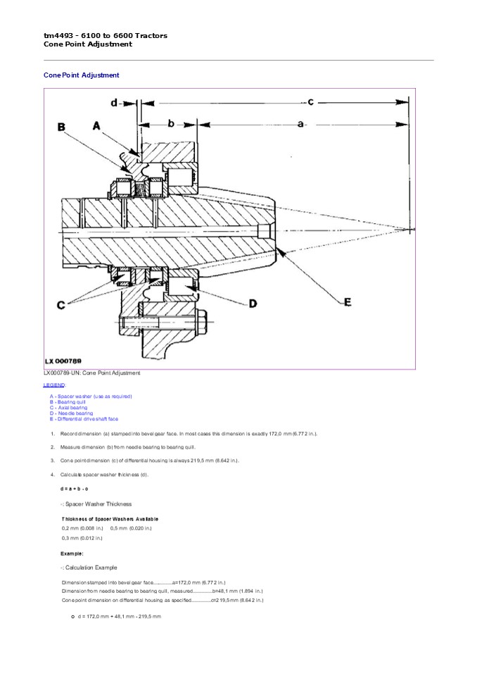
- LX000789-UN Cone Point Adjustment
- LEGEND
- A - Spacer washer (use as required) B - Bearing
quill - C - Axial bearing
- D - Needle bearing
- E - Differential drive shaft face
- Record dimension (a) stamped into bevel gear
face. In most cases this dimension is exactly
172,0 mm (6.772 in.). - Measure dimension (b) from needle bearing to
bearing quill. - Cone point dimension (c) of differential housing
is always 219,5 mm (8.642 in.). - Calculate spacer washer thickness (d).
- d a b - c
- - Spacer Washer Thickness
2
- d 0,6 mm
- d 6.772 in. 1.894 in. - 8.642 in.
- d 0.024 in.
- In the example two 0,3 mm (0.012 in.) spacer
washers have to be used.
LX000790-UN Locking Latch and Taper Roller
Bearing Cup Press taper roller bearing cup (B)
into bearing quill. Install locking latch (A).
LX000791-UN Tighten Screws and Bolt Attach
bearing quill. Tighten screws (A and C) and bolt
(B) to 55 Nm (40 lb-ft).
LX000792-UN Install Shifter Shaft
Housing Install shifter shaft housing (A).
LX000793-UN Install Spacer and Snap Ring Install
spacer Older tractors only (A).
3
Install snap ring (B).
LX000794-UN Front Wheel Drive Gear and Snap
Ring Install front wheel drive gear (A) and snap
ring (B).
LX009123-UN Check Axial Play Check axial play of
front wheel drive gear. NOTE Front wheel drive
gear axial play must be less than 0.1 mm (0.004
in.). If axial play is not correct, use a
different size snap ring to install the front
wheel drive gear. - Snap Ring
Thickness Thickness of Snap Rings Available 2.0
mm (0.079 in.) 2.2 mm (0.087 in.) 2.1 mm (0.083
in.) 2.3 mm (0.091 in.)
LX000795-UN Install Thrust Washer and Snap
Ring Install thrust washer and gear of range A
(A). Install snap ring (B).
4
https//www.ebooklibonline.com Hello dear
friend! Thank you very much for reading. Enter
the link into your browser. The full manual is
available for immediate download. https//www.eb
ooklibonline.com
5
LX000796-UN Install Synchronizer Unit and Snap
Ring Install synchronizer unit (B) and snap ring
(A). NOTE Axial play of synchronizer unit must
be less than 0.1 mm (0.004 in.). - Snap Ring
Thickness Thickness of Snap Rings Available 2.0
mm (0.079 in.) 2.2 mm (0.087 in.) 2.1 mm (0.083
in.) 2.3 mm (0.091 in.)
LX000797-UN Check Gear Axial Play Check axial
play of gear for range A. IMPORTANT When
measuring axial play, use both hands to guide the
gear onto the shaft. Make sure the gear is
straight (i.e. not skewed). NOTE Axial play of
gear must be 0.15 to 0.6 mm (0.006 to 0.024
in.). If axial play is not correct, use a
different size thrust washer to install gear of
range A. - Thrust Washer Thickness Thickness
of Thrust Washers Available 3.65 mm (0.144 in.)
3.95 mm (0.156 in.) 3.80 mm (0.150 in.)
LX000798-UN Snap Ring, Thrust Washer and
Gear Install gear of range B (C) and thrust
washer (B).
6
Install snap ring (A). IMPORTANT When
measuring axial play, use both hands to guide the
gear onto the shaft. Make sure the gear is
straight (i.e. not skewed). NOTE Axial play of
gear must be 0.15 to 0.6 mm (0.006 to 0.024
in.). - Thrust Washer Thickness Thickness of
Thrust Washers Available 3.65 mm (0.144 in.) 3.95
mm (0.156 in.) 3.80 mm (0.150 in.) IMPORTANT Up
to transmission serial no. 157465, snap ring (A)
had a thickness of 2.0 mm (0.079 in.). When
repairing, put additional washer L112108 on the
outside of the snap ring.
LX000799-UN Install Snap Ring and Thrust
Washer Install thrust washer and gear of range C
(B). Install snap ring (A).
LX000800-UN Install Synchronizer Unit Snap
Ring Install synchronizer unit (B) and snap ring
(A). NOTE Axial play of synchronizer unit must
be less than 0.1 mm (0.004 in.). - Snap Ring
Thickness Thickness of Snap Rings Available 2.0
mm (0.079 in.) 2.2 mm (0.087 in.) 2.1 mm (0.083
in.) 2.3 mm (0.091 in.)
7
LX000801-UN Check Gear Axial Play Check axial
play of gear for range C. IMPORTANT When
measuring axial play, use both hands to guide the
gear onto the shaft. Make sure the gear is
straight (i.e. not skewed). NOTE Axial play of
gear must be 0.15 to 0.6 mm (0.006 to 0.024
in.). If axial play is not correct, use a
different size thrust washer to install gear of
range C. - Thrust Washer Thickness Thickness
of Thrust Washers Available 3.65 mm (0.144 in.)
3.95 mm (0.156 in.) 3.80 mm (0.150 in.)
LX000802-UN Install Gear, Thrust Washer Snap
Ring Install gear of range D (C) with connecting
ring. Install thrust washer (B) and snap ring
(A). IMPORTANT When measuring axial play, use
both hands to guide the gear onto the shaft. Make
sure the gear is straight (i.e. not
skewed). NOTE Axial play of gear must be 0.15
to 0.6 mm (0.006 to 0.024 in.). - Thrust Washer
Thickness Thickness of Thrust Washers
Available 3.65 mm (0.144 in.) 3.95 mm (0.156
in.) 3.80 mm (0.150 in.)
8
LX000803-UN Range Transmission
Assembly LEGEND A - Ball B - Shaft C -
Bushing D - Cap screw (2 used) E - Cap screw F -
Thrust washer G - Double gear H - Needle race I
- Thrust washer J - Needle race K - Spacer
bushing L - Double gear M - Bolt N - Idler gear
housing O - Shaft Assemble idler gear housing
15- and 18-gear versions (SyncroPlus) or 20 and
24-gear versions (PowrQuad) .
LX000804-UN Tighten Cap Screws Install idler
gear housing 15- and 18-gear versions
(SyncroPlus) or 20 and 24-gear versions
(PowrQuad) . Tighten cap screws to 55 Nm (40
lb-ft).
9
LX009122-UN Shifter Shafts and Shifter
Forks LEGEND A - Shifter shaft (ranges A and B)
B - Shifter fork (ranges A and B) C - Shifter
fork (ranges C and D) D - Shifter shaft (ranges
C and D) Install shifter shafts and shifter
forks.
LX009124-UN Taper Roller Bearing Cones Press
taper roller bearing cones (A) and (B) onto drive
shaft.
LX009121-UN Install Drive Shaft and
Spring Install drive shaft (B). Connect spring
(A) of parking lock.
10
LX009359-UN Install Parking Lock Shifter
Cam LEGEND A - Lever B - Spring C - Seal
ring D - Bushing (2 used) E - Spring pin F -
Shifter cam G - Spacer washer (thickness as
required) H - Axial bearing assy. Install
parking lock shifter cam in the transmission
housing. Use a 1.6 mm (0.063 in.) spacer washer
(G) (recommended average setting).
LX1016989-UN Install Shifter Shaft Stop
Assy. Referring to the exploded view, assemble
and install the fwd/rev. shifter shaft (A) and
stop assembly (B if equipped).
LX009125-UN Install Transmission Housing Install
transmission housing.
11
Tighten cap screws. Item Measurement Specification
Grade 8.8 Cap Screw Torque 90 Nm (65 lb-ft)
Grade 10.9 Cap Screw Torque 120 Nm (90 lb-ft)
LX009360-UN Parking lock disengaged
- LX009361-UN Parking lock engaged, play
- Check play of parking lock shifter cam as
follows - Engage parking lock. Turn shifter cam to end
point, then back 10 degrees so that the cam is no
longer touching. - Attach dial gauge to shifter cam. Use a suitable
lever or screwdriver to press the locking latch
against the teeth of front wheel drive gear and
measure the play of the shifter cam. - Play must be between 0.25 and 0.60 mm (0.010 and
0.024 in.). - If play is excessive, the transmission housing
must removed once more and a larger spacer washer
used (see Install parking lock shifter cam). If
play is insufficient, a smaller spacer washer
must be used. - - Space Washer Thickness
- Thickness of Spacer Washer Available
1.7 mm (0.067 in.) 1.8 mm (0.071 in.) 1.9 mm
(0.075 in.) 2.0 mm (0.079 in.)
1.2 mm (0.047 in.) 1.3 mm (0.051 in.) 1.4 mm
(0.055 in.) 1.5 mm (0.059 in.) 1.6 mm (0.063 in.)
LX009126-UN Install Taper Roller Bearing
Cup LEGEND A - Snap ring (thickness as
required) B - Taper roller bearing cup
12
C - Needle bearing D - Cap screw Later tractor
series have 2 cap screws Install taper roller
bearing cup (B) of drive shaft and needle bearing
(C) of differential drive shaft.
LX009127-UN Check Drive Shaft Axial Play Check
axial play of drive shaft. NOTE Axial play of
drive shaft must be less than 0.1 mm (0.004
in.). If axial play is not correct, use a
different size snap ring to install the taper
roller bearing cup. - Snap Ring
Thickness Thickness of Snap Rings Available 2.0
mm (0.079 in.) 2.2 mm (0.087 in.) 2.1 mm (0.083
in.) 2.3 mm (0.091 in.)
LX009128-UN Tighten Cap Screw Tighten cap screw
to 30 Nm (22 lb-ft).
LX013472-UN Countersunk Screw Coat the thread
on countersunk screw 12-gear version
(SyncroPlus) and 16-gear version (Power Reverser
or PowrQuad) only (A) with LOCTITE E 648
(L41860) and tighten it to 25 Nm (18 lb-ft).
LOCTITE is a trademark of Loctite Corp.
LX,5030 009469-19-1997/06/01
13
tm4493 - 6100 to 6600 Tractors Adjusting Shift
Mechanism
Adjusting Shift Mechanism 1. Place shifter
shafts in neutral position.
- 2.
- LX000810-UN Threaded Pins
- Adjust shifter forks by means of threaded pins
(A) until they are centered in relation to shift
collars. - Move shifter forks to all positions.
- NOTE
- Make sure that shifter forks do not rub laterally
on shift collars in any shift position. - Tighten threaded pins to 40 Nm (30 lb-ft).
- Recheck adjustment.
LX,RDTG 002138-19-1996/04/01
14
tm4493 - 6100 to 6600 Tractors Final Assembly
- Final Assembly
- Install front wheel drive clutch, see Section 56,
Group 10. - If equipped, install option transmission or
creeper transmission, see Group 00. - SyncroPlus Install PERMA-CLUTCH 2 and gear
transmission. See Group 00. - PowrQuad Install PowrQuad module. See Group
00. Install forward/reverse linkage. See Section
55, Group 05. - Install differential, see Section 56, Group 15.
- Install final drives, see Section 56, Group 00.
6. Install PTO, see Section 56, Group 00.
LX009129-UN Tighten Cap Screws Install shift
cover. Tighten cap screws to 30 Nm (22 lb-ft).
SyncroPlus is a trademark of Deere
Company. PERMA-CLUTCH 2 is a trademark of Deere
Company. PowrQuad is a trademark of Deere
Company.
LX,RDTG 002139-19-1994/06/01
15
tm4493 - 6100 to 6600 Tractors Special or
Essential Tools
Special or Essential Tools NOTE Order tools
according to information given in the U.S.
SERVICEGARD Catalog or in the European
Microfiche Tool Catalog (MTC). Tilting
device.......KJD10178 Tilting the cab up and down
KJD10178-UN KJD10178
Universal support stand Additionally
required 1 commercial 12 ton jack
.......JT05725 Supporting tractor during rear
wheel removal.
JT05725-UN JT05725 Puller.......KJD10173 Remova
l and installation
16
of PTO drive shaft and pump drive shaft
KJD10173-UN KJD10173 Lifting
eye.......JD-244-1 Removal and installation of
tractor components
LX002476-UN JD-244-1
Lifting eye.......JD-244-2 Removal and
installation of tractor components
LX002297-UN JD-244-2
SERVICEGARD is a trademark of Deere Company.
LX,CRA50 002753-19-1993/10/01
17
tm4493 - 6100 to 6600 Tractors
Dealer-Manufactured Special Tools
Dealer-Manufactured Special Tools See also
Section 99, Group 05.
LX1016738-UN Lifting Device Lifting device for
clutch housing and PowrReverser module.
PowrReverser is a trademark of Deere Company.
LX,5100 012015-19-1997/06/01
18
tm4493 - 6100 to 6600 Tractors Specifications
Specifications
Item U.j. shaft to drive flange, corrugated-
head screws
Measurement Torque
Specification 135 Nm (100 lb-ft)
PowrReverser module to gear transmission, cap
screws
Torque
50 Nm (35 lb-ft)
Clutch bowden cable support to clutch housing,
cap screws
Torque
11 Nm (8 lb-ft)
Suction line of transmission oil pump to clutch
housing, hex. socket screws Rear wheel to rear
axle Tractors with flanged axle, cap
screws Transmission oil, 6100 - 6400 Tractors
Torque
18 Nm (13.3 lb-ft)
Torque
500 Nm (370 lb-ft)
Capacity
52 L (13.7 U.S.gal.) approx. See Section 10,
Group 05.
PowrReverser is a trademark of Deere Company.
LX,5100 012013-19-1997/06/01
19
tm4493 - 6100 to 6600 Tractors Removing the
PowrReverser Module
Removing the PowrReverser Module
LX1016498-UN PowrReverser Module
LX002206-UN Tilt Operator's Cab For tilting the
operator's cab, see Section 90, Groups 00 and 01.
20
LX007211-UN Remove Oil Drain Plugs Pull out
swinging drawbar to the rear. Remove oil drain
plugs (A) and (B). Drain transmission oil into a
suitable container. Capacity oil and filter
change approx. 52 L (13.7 U.S. gal.) Refer to
Section 10, Group 05 for the precise oil capacity.
LX002223-UN Remove Plug Remove plug (A).
LX002599-UN PTO Drive Shaft and Puller Pull PTO
drive shaft (A) and then pump drive shaft out of
housing by means of puller KJD10173 (B).
LX1016495-UN Remove Bracket Remove bracket (A).
21
LX1015880-UN Oil Cooler Hoses Disconnect oil
cooler hoses (A) and (B) where they meet the
Power Reverser module.
LX007768-UN Remove Cap Screws Take out cap
screws (A) and (B), and remove the u.j.
shaft. See also Section 56, Group 05.
LX1016742-UN Disconnect Cables and
Plugs Disconnect cables and plugs (A) to (D).
LX1016736-UN Remove Screws, Suction Line and
Linkage Take out screws (A) and pull suction line
(B) out of the differential housing. NOTE Trap
the oil as it emerges from the suction
line. Disengage forward/reverse linkage (C).
22
LX1016740-UN Remove Return Hose Remove return
hose (A).
LX1016737-UN Remove Pressure Line Remove
pressure line (A).
LX1016496-UN Install Lifting Device and Cap
Screw Install lifting device (A) as shown, and
secure it with cap screw (B). Attach lifting
tackle.
LX1016739-UN Remove Screws from Housing
Flange Take screws (A) out of the housing flange
and remove the PowrReverser module. NOTE Screw
(B) remains in place.
PowrReverser is a trademark of Deere Company.
LX,5100 012021-19-1997/06/01
23
tm4493 - 6100 to 6600 Tractors Installing the
PowrReverser Module
Installing the PowrReverser Module Clean the
sealing surfaces thoroughly and install a new
flange seal. Attach the lifting device and
tackle to the PowrReverser module.
LX1016741-UN Install Cap Screws Install the
PowrReverser module. Install cap screws (A) and
tighten them to 50 Nm (35 lb-ft).
LX1016736-UN Suction Line, Screws and
Linkage Put new seals on the suction line (B),
and install the suction line on the PowrReverser
module and differential housing. Tighten screws
(A) to 18 Nm (13.3 lb-ft). Adjust and install
forward/reverse linkage (C). See Group 05 in this
Section. For installation of u.j. shaft, refer
to Section 56, Group 05. For further assembly,
reverse disassembly procedure. Install oil drain
plugs, fill with transmission oil, and check the
oil level. Tilt down the operator's cab. See
Section 90. Check all the functions of the
tractor. If necessary, rectify any faults as
described in the Technical Manual.
24
Suggest If the above button click is invalid.
Please download this document first, and then
click the above link to download the complete
manual. Thank you so much for reading
25
tm4493 - 6100 to 6600 Tractors Removing and
Installing the Gear Transmission
Removing and Installing the Gear
Transmission NOTE To remove or install the gear
transmission, see Section 50, Group 00 (
SyncroPlus transmission). NOTE See Group 15
in this Section for measuring the gaps at the
connecting ring.
SyncroPlus is a trademark of Deere Company.
LX,5100 012068-19-1997/06/01
26
https//www.ebooklibonline.com Hello dear
friend! Thank you very much for reading. Enter
the link into your browser. The full manual is
available for immediate download. https//www.eb
ooklibonline.com
Recommended
CrystalGraphics Presentations


