

Isuzu 4JA1, 4JB1, 4JC1 Diesel Engine Service Repair Manual Instant Download PowerPoint PPT Presentation
Title: Isuzu 4JA1, 4JB1, 4JC1 Diesel Engine Service Repair Manual Instant Download
1
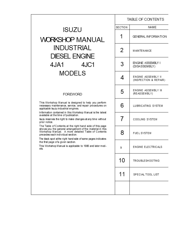
lSUZU WORKSHOP MANUAL INDUSTRIAL DIESEL ENGINE 4JA1 4JC1 MODELS FOREWORD This Workshop Manual is designed to help you perform necessary maintenance, service, and repair procedures on applicable lsuzu industrial engines. Information contained in this Workshop Manual is the latest available at the time of publication. lsuzu reserves the right to make changes at any time without prior notice. The Table of Contents at the right hand side of this page shows you the general arrangement of the material in this Workshop Manual. A more detailed Table of Contents precedes each individual section. The black spot at the right hand side of some pages indicates the first page of a given section. This Workshop Manual is applicable to 1986 and later mod- els. TABLE OF CONTENTS TABLE OF CONTENTS
lSUZU WORKSHOP MANUAL INDUSTRIAL DIESEL ENGINE 4JA1 4JC1 MODELS FOREWORD This Workshop Manual is designed to help you perform necessary maintenance, service, and repair procedures on applicable lsuzu industrial engines. Information contained in this Workshop Manual is the latest available at the time of publication. lsuzu reserves the right to make changes at any time without prior notice. The Table of Contents at the right hand side of this page shows you the general arrangement of the material in this Workshop Manual. A more detailed Table of Contents precedes each individual section. The black spot at the right hand side of some pages indicates the first page of a given section. This Workshop Manual is applicable to 1986 and later mod- els. SECTION NAME
lSUZU WORKSHOP MANUAL INDUSTRIAL DIESEL ENGINE 4JA1 4JC1 MODELS FOREWORD This Workshop Manual is designed to help you perform necessary maintenance, service, and repair procedures on applicable lsuzu industrial engines. Information contained in this Workshop Manual is the latest available at the time of publication. lsuzu reserves the right to make changes at any time without prior notice. The Table of Contents at the right hand side of this page shows you the general arrangement of the material in this Workshop Manual. A more detailed Table of Contents precedes each individual section. The black spot at the right hand side of some pages indicates the first page of a given section. This Workshop Manual is applicable to 1986 and later mod- els. 1 GENERAL INFORMATION
lSUZU WORKSHOP MANUAL INDUSTRIAL DIESEL ENGINE 4JA1 4JC1 MODELS FOREWORD This Workshop Manual is designed to help you perform necessary maintenance, service, and repair procedures on applicable lsuzu industrial engines. Information contained in this Workshop Manual is the latest available at the time of publication. lsuzu reserves the right to make changes at any time without prior notice. The Table of Contents at the right hand side of this page shows you the general arrangement of the material in this Workshop Manual. A more detailed Table of Contents precedes each individual section. The black spot at the right hand side of some pages indicates the first page of a given section. This Workshop Manual is applicable to 1986 and later mod- els. 2 MAINTENANCE
lSUZU WORKSHOP MANUAL INDUSTRIAL DIESEL ENGINE 4JA1 4JC1 MODELS FOREWORD This Workshop Manual is designed to help you perform necessary maintenance, service, and repair procedures on applicable lsuzu industrial engines. Information contained in this Workshop Manual is the latest available at the time of publication. lsuzu reserves the right to make changes at any time without prior notice. The Table of Contents at the right hand side of this page shows you the general arrangement of the material in this Workshop Manual. A more detailed Table of Contents precedes each individual section. The black spot at the right hand side of some pages indicates the first page of a given section. This Workshop Manual is applicable to 1986 and later mod- els. 3 ENGINE ASSEMBLY I (DISASSEMBLY)
lSUZU WORKSHOP MANUAL INDUSTRIAL DIESEL ENGINE 4JA1 4JC1 MODELS FOREWORD This Workshop Manual is designed to help you perform necessary maintenance, service, and repair procedures on applicable lsuzu industrial engines. Information contained in this Workshop Manual is the latest available at the time of publication. lsuzu reserves the right to make changes at any time without prior notice. The Table of Contents at the right hand side of this page shows you the general arrangement of the material in this Workshop Manual. A more detailed Table of Contents precedes each individual section. The black spot at the right hand side of some pages indicates the first page of a given section. This Workshop Manual is applicable to 1986 and later mod- els. 4 ENGINE ASSEMBLY II (INSPECTION REPAIR)
lSUZU WORKSHOP MANUAL INDUSTRIAL DIESEL ENGINE 4JA1 4JC1 MODELS FOREWORD This Workshop Manual is designed to help you perform necessary maintenance, service, and repair procedures on applicable lsuzu industrial engines. Information contained in this Workshop Manual is the latest available at the time of publication. lsuzu reserves the right to make changes at any time without prior notice. The Table of Contents at the right hand side of this page shows you the general arrangement of the material in this Workshop Manual. A more detailed Table of Contents precedes each individual section. The black spot at the right hand side of some pages indicates the first page of a given section. This Workshop Manual is applicable to 1986 and later mod- els. 5 ENGINE ASSEMBLY III (REASSEMBLY)
lSUZU WORKSHOP MANUAL INDUSTRIAL DIESEL ENGINE 4JA1 4JC1 MODELS FOREWORD This Workshop Manual is designed to help you perform necessary maintenance, service, and repair procedures on applicable lsuzu industrial engines. Information contained in this Workshop Manual is the latest available at the time of publication. lsuzu reserves the right to make changes at any time without prior notice. The Table of Contents at the right hand side of this page shows you the general arrangement of the material in this Workshop Manual. A more detailed Table of Contents precedes each individual section. The black spot at the right hand side of some pages indicates the first page of a given section. This Workshop Manual is applicable to 1986 and later mod- els. 6 LUBRICATING SYSTEM
lSUZU WORKSHOP MANUAL INDUSTRIAL DIESEL ENGINE 4JA1 4JC1 MODELS FOREWORD This Workshop Manual is designed to help you perform necessary maintenance, service, and repair procedures on applicable lsuzu industrial engines. Information contained in this Workshop Manual is the latest available at the time of publication. lsuzu reserves the right to make changes at any time without prior notice. The Table of Contents at the right hand side of this page shows you the general arrangement of the material in this Workshop Manual. A more detailed Table of Contents precedes each individual section. The black spot at the right hand side of some pages indicates the first page of a given section. This Workshop Manual is applicable to 1986 and later mod- els. 7 COOLING SYSTEM
lSUZU WORKSHOP MANUAL INDUSTRIAL DIESEL ENGINE 4JA1 4JC1 MODELS FOREWORD This Workshop Manual is designed to help you perform necessary maintenance, service, and repair procedures on applicable lsuzu industrial engines. Information contained in this Workshop Manual is the latest available at the time of publication. lsuzu reserves the right to make changes at any time without prior notice. The Table of Contents at the right hand side of this page shows you the general arrangement of the material in this Workshop Manual. A more detailed Table of Contents precedes each individual section. The black spot at the right hand side of some pages indicates the first page of a given section. This Workshop Manual is applicable to 1986 and later mod- els. 8 FUEL SYSTEM
lSUZU WORKSHOP MANUAL INDUSTRIAL DIESEL ENGINE 4JA1 4JC1 MODELS FOREWORD This Workshop Manual is designed to help you perform necessary maintenance, service, and repair procedures on applicable lsuzu industrial engines. Information contained in this Workshop Manual is the latest available at the time of publication. lsuzu reserves the right to make changes at any time without prior notice. The Table of Contents at the right hand side of this page shows you the general arrangement of the material in this Workshop Manual. A more detailed Table of Contents precedes each individual section. The black spot at the right hand side of some pages indicates the first page of a given section. This Workshop Manual is applicable to 1986 and later mod- els. 9 ENGINE ELECTRICALS
lSUZU WORKSHOP MANUAL INDUSTRIAL DIESEL ENGINE 4JA1 4JC1 MODELS FOREWORD This Workshop Manual is designed to help you perform necessary maintenance, service, and repair procedures on applicable lsuzu industrial engines. Information contained in this Workshop Manual is the latest available at the time of publication. lsuzu reserves the right to make changes at any time without prior notice. The Table of Contents at the right hand side of this page shows you the general arrangement of the material in this Workshop Manual. A more detailed Table of Contents precedes each individual section. The black spot at the right hand side of some pages indicates the first page of a given section. This Workshop Manual is applicable to 1986 and later mod- els. 10 TROUBLESHOOTING
lSUZU WORKSHOP MANUAL INDUSTRIAL DIESEL ENGINE 4JA1 4JC1 MODELS FOREWORD This Workshop Manual is designed to help you perform necessary maintenance, service, and repair procedures on applicable lsuzu industrial engines. Information contained in this Workshop Manual is the latest available at the time of publication. lsuzu reserves the right to make changes at any time without prior notice. The Table of Contents at the right hand side of this page shows you the general arrangement of the material in this Workshop Manual. A more detailed Table of Contents precedes each individual section. The black spot at the right hand side of some pages indicates the first page of a given section. This Workshop Manual is applicable to 1986 and later mod- els. 11 SPECIAL TOOL LIST
lSUZU WORKSHOP MANUAL INDUSTRIAL DIESEL ENGINE 4JA1 4JC1 MODELS FOREWORD This Workshop Manual is designed to help you perform necessary maintenance, service, and repair procedures on applicable lsuzu industrial engines. Information contained in this Workshop Manual is the latest available at the time of publication. lsuzu reserves the right to make changes at any time without prior notice. The Table of Contents at the right hand side of this page shows you the general arrangement of the material in this Workshop Manual. A more detailed Table of Contents precedes each individual section. The black spot at the right hand side of some pages indicates the first page of a given section. This Workshop Manual is applicable to 1986 and later mod- els.
2
STANDARD TIGHTENING TORQUE TABLE FOR FLANGED
HEX HEAD BOLTS The tightening torques in the
next table apply to such areas that do not
specify special tightening torques.
It has been decided to use flanged hex head
bolts in place of hex head bolts. The tightening
torques for the flanged hex head bolts have been
increased by about 10 as compared to
conventional torques in order to get the same
axial force as conven- tional her head bolts,
except part of special bolts (connecting rod
bolts, etc.). Y'e therefore request that this
decision be made known to all personnel of your
service department by referring (o standard
tightening torques for conventional hex head
bolts and new flanged hex head bolts. At the
latter part of August 1995. Present) fiNe I
1 . Reason for change
- Time of execution
- Change contents
- Hez head bolt
- Interchangeability New Old
- Applicable engine model All engines
Flangehex head bolt
kg a
(lb k)
Class 4.8 8.8 9.8
identification Bolt diameter X pitch mm
M 6 x 1.0 0.5-0.g (s.s-6.5) 0.6-1.2 (4.6-8.7)
M 8X 1.25 1.1-2.0 (8.0-14) 1.6-2.9 (12-21) 2.1-3.4 (15-25)
M10 x 1.25 2.4-3.9 (17-28) 3.6-6.1 (26-44) 4.3-7.2 (31-52)
E M10X 1.5 2.3-3.8 (17-27) 3.5-5.8 (25-42) 4.1-6.8 (30-49)
M12X 1.25 5.6-8.4 (41-61) 7.9-1 1.9 (57-86) 8.7 13.0 (63-94)
X M12 x 1.75 5.2-7.8 38-56) 7.2-10.9 (52-79) 8.1-12.2 (59-88)
M14X 1.5 8.5-12.7 (61 -92) \1.7-17.6 t85-127) 12.6-18.9 (91-137)
M14 x 2.0 7.9-11.8 (57-85) 1 1.1-16.6 (80-120) 11.8-17.7 (85-128)
M16X 1.5 11.8-17.7 (85-128) 17.4-26.2 (126-190) 18.0-27.1 (130-196)
K M16y 2.0 11.2-16.7 (81-121) 16.6-24.9 ( 120-180) 17.2-25.8 (124-187)
lt mark is used for female-threaded parts made
of soft material, such as casting.
3
GENERAL INFORMATION 1- 1 SECTION 1 GENERAL
INFORMATION TABLE OF CONTENTS
ITEM
PAGE
General repair instructions .....................
.................................... 1 2 Notes
on the format of this manual .....................
............................ 1 2 Main data and
specifications ...................................
..................... 1 6 Tightening torque
specifications ...................................
................. 1 7
NOTICE Before using this Workshop Manual to
assist you in per- forming engine service and
maintenance operations, it recommended that you
carefully read and throughly understand the
information contained in Section - 1 under the
headings "GENERAL REPAIR INSTRUCTION and NOTES
ON THE FORMAT OF THIS MANUAL
4
https//www.ebooklibonline.com Hello dear
friend! Thank you very much for reading. Enter
the link into your browser. The full manual is
available for immediate download. https//www.ebo
oklibonline.com
5
12 GENERAL INFORMATION
- GENERAL REPAIR INSTRUCTIONS
- Before performing any service operation with the
engine mounted, disconnect the grounding cable
from the battery. - This will reduce the chance of cable damage and
burning due to short circuiting. - Always use the proper tool or tools for the job
at hand. Where specified, use the specially
designed tool or tools. - Use genuine ISUZU parts.
- Never reuse cotter pins, gaskets, O-rings, lock
washers, and self locking nuts. Discard them as
you remove them. Replace them with new ones. - Always keep disassembled parts neatly in
groups. This will ensure a smooth reassembly
operation. - It is especially important to keep fastening
parts separate. These parts vary in hardness and
design, depending on their installation position. - All parts should be carefully cleaned before
inspection or reassembly. - Oil ports and other openings should be cleaned
with compressed air to make sure that they are
completely free of obstructions. - Rotating and sliding part surfaces should be
lubricated with oil or grease before reassembly. - If necessary, use a sealer on gaskets to prevent
leakage. - Nut and bolt torque specifications should be
carefully followed. - Always release the air pressure from any
machine-mounted air tank(s) before dismounting
the engine or disconnecting pipes and hoses. To
not do so is extremely dangerous. - Always check and recheck your work. No service
operation is complete until you have done this.
- NOTES ON THE FORMAT OF THIS MANUAL
- This Workshop Manual is applicable to ISUZU
industrial engine or engines which is or are
stated in the title. - When more than two engine models are dealt in the
manual, such engines have common parts and
components as well as data and specifications,
unless otherwise specified. - Find the applicable section by referring to the
Table of Contents at the beginning of the Manual. - Common technical data such as genral maintenance
items, service specifications, and tightening
torques are included in the General
Information" section. - The section ENGINE ASSEMBLY is an exception. This
parts are divided in three sections to facili-
tates indexing. - Each section is divided into sub-sections dealing
with disassembly, inspection and repair, and
reas- sembly.
6
- GENERAL INFORMATION 13
- When the same servicing operation is applicable
to several different units, the manual will
direct you to the appropriate page. - For the sake of brevity, self-explanatory removal
and installation procedures are omitted. More
complex procedures are covered in detail. - Each service operation section in this Workshop
Manual begins with an exploded view of the
applic- able area. A brief explanation of the
notation used follows. - Parts marked with an asterisk () are included
in the repair kit. - Parts within a square frame are to be removed and
installed as a single unit, and their disassembly
steps or reas- sembly steps are shown in the
illustrations respectively. - The number tells you the service oper- ation
sequence. - Removal of unnumbered parts is unne- cessary
unless replacement is required. - The Repair Kit indicates that a repair
kit is available. - The parts listed under Disassembly Steps or
Reassembly Steps are in the service operation
sequence.
7
1-4 GENERAL INFORMATION 7. Below is a sample of
the text of the Workshop Manual.
This is the item shown in the illus- tration. It is marked with a triangle (1) on the Major Components page.
This is the item shown in the illus- tration. It is marked with a triangle (1) on the Major Components page.
g
g Letters and numbers contained in a circle refer to the illustration.
Special tools are identified by the tool name and/or number.
The illustration shows how the spe- cial tool is to be used.
Symbols indicate the type of r.ervice operation or step to be per- formed. A detailed explanation of these symbols follows.
Symbols indicate the type of r.ervice operation or step to be per- formed. A detailed explanation of these symbols follows.
Service data and specifications are given in this table.
8. The following symbols appear throughout this
Workshop Manual. operation or step to perform.
They tell you the type of service
Removal
Adjustment
Installation
Cleaning
Important operation requiring extra care
Disassembly
Reassembly
Specified torque (tighten)
Special tool use requireci or recom- mended
(Isuzu tool or tools)
Alignment (marks)
Commercially available tool use required or
recommended
Directional indication
Inspection
Lubrication (oil)
Measurement
Lubrication (grease)
Liquid gasket application
8
- GENERAL INFORMATION 1-5
- Measurement criteria are defined by the terms
"standard" and "limit". - A measurement falling within the "standard" range
indicates that the applicable part or parts are
ser- - viceable.
- "Limit" should be thought of as an absolute
value. - A measurement which is outside the "limit"
indicates that the applicable part or parts must
be either repaired or replaced. - Components and parts are listed in the singular
form throughout the Manual. - Directions used in this Manual are as follows
Front - The cooling fan side of the engine viewed from
the flywheel. - Right
- The right hand side viewed from the same
position. - Left
- The left hand side viewed from the same position.
Rear - The flywheel side of the engine.
- Cylinder numbers are counted from the front of
the engine. - The front most cylinder is No. 1 and rear most
cylinder is the final cylinder number of the
engine. - The engine's direction of rotation is
counterclockwise viewed from the flywheel.
9
16 GENERAL INFORMATION MAIN DATA AND
SPECIFICATIONS
Engine Model Item 4JA1 4JBΠ4JC1
Engine type Water cooled, four-cycle, in-line, overhead valve Water cooled, four-cycle, in-line, overhead valve Water cooled, four-cycle, in-line, overhead valve
Combustiön chamber type Direct injection Direct injection Direct injection
Cylinder liner type Dry Dry Dry
No. of cylinders - Bore x Stroke mm(in.) 4-93.0x92.0 4-93.0x102.0 4-88.0x92.0 4-93.0x92.0 4-93.0x102.0 4-88.0x92.0 4-93.0x92.0 4-93.0x102.0 4-88.0x92.0
(3.66x3.62) (3.66x4.02) (3.46x3.62) (3.66x3.62) (3.66x4.02) (3.46x3.62) (3.66x3.62) (3.66x4.02) (3.46x3.62)
Total piston displacement cm(in) 2,449(152.4) 2,771(169.0) 2,238(136.5) 2,449(152.4) 2,771(169.0) 2,238(136.5) 2,449(152.4) 2,771(169.0) 2,238(136.5)
Compression ratio (To 1) 18.4 18.2 19.0 18.4 18.2 19.0 18.4 18.2 19.0
Engine dimensions mm(in.) 805x590x725 760x 620x710 717x590x725 805x590x725 760x 620x710 717x590x725 805x590x725 760x 620x710 717x590x725
Length x Width x Height (31.7x23.2x28.5) (29.9 x 24.4X28.0) (28.2x23.2x28.5) (31.7x23.2x28.5) (29.9 x 24.4X28.0) (28.2x23.2x28.5) (31.7x23.2x28.5) (29.9 x 24.4X28.0) (28.2x23.2x28.5)
Engine weight (Dry) kg(Ib.) 218 (480) 240(529) 218 (480) 218 (480) 240(529) 218 (480) 218 (480) 240(529) 218 (480)
Fuel injection order 1342 1342 1342
Fuel injection timing (B.T.D.C.) degrees 17 17 17
Specified fuel Diesel fuel Diesel fuel Diesel fuel
Injection pump In-line plunger, Bosch A type In-line plunger, Bosch A type In-line plunger, Bosch A type
Governor Mechanical, RSV type Mechanical, RSV type Mechanical, RSV type
Low idle speed rpm 980-1020 980-1020 980-1020
Injection nozzle Hole type (with 4 orifices) Hole type (with 4 orifices) Hole type (with 4 orifices)
Injection starting pressure kg/cm(psi)/kPa) 185 (2630/18,142) 185 (2630/18,142) 185 (2630/18,142)
Fuel filter type Cartridge paper element Cartridge paper element Cartridge paper element
Water sedimentor (if so equipped) Sediment/water level indicating type Sediment/water level indicating type Sediment/water level indicating type
Compression pressure kg/cm2(psi)/kPa) 30(4 2,942) 30(4 2,942) 30(4 2,942)
Valve clearance (at cold) Intake mm(in.) 0.40jQÎ016) 0.40jQÎ016) 0.40jQÎ016)
Exhaust mm(in.) 0.40 (0.016) 0.40 (0.016) 0.40 (0.016)
Lubrication method Pressurized circulation Pressurized circulation Pressurized circulation
Oil p P Trochoid type Trochoid type Trochoid type
Main oil filter type Cartridge paper element, full flow Cartridge paper element, full flow Cartridge paper element, full flow
Partial oil filter Not equipped Not equipped Not equipped
Lubricating oil capacity lit.(US/UK gal.) 7(1.85 1.54) 7(1.85 1.54) 7(1.85 1.54)
Oil cooler (if so equipped) Water cooled built in oil filter Water cooled built in oil filter Water cooled built in oil filter
Cooling method Pressurized forced circulation Pressurized forced circulation Pressurized forced circulation
Coolant capacity (Total) lit.(US/UK gal.) 12(3.17X2.64) 12(3.17X2.64) 12(3.17X2.64)
Water pump Belt driven impeller type Belt driven impeller type Belt driven impeller type
Thermostat type Wax pellet type Wax pellet type Wax pellet type
Alternator V-A 2430 2430 2430
Starter V-kW 243.2 243.2 243.2
Specifications marked with an asterisk () will
vary according to engine application.
10
GENERAL INFORMATION 17 TIGHTENING TORQUE
SPECIFICATION STANDARD BOLTS The torque values
given in the following table should be applied
where a particular torque is not specified. kg
m(lb.ft./N m)
Bolt identification Bolt diameter x pitch mm
Bolt identification Bolt diameter x pitch mm 4T (Low carbon steel) (High carbon steel) 9T (Alloy steel)
M 6 x 1.0 0.6 0.2 ( 4.4 1.4 / 5.88 1.96) 0.75 0.2 ( 5.43 1.43/ 7.35 1.96)
M 8 x 1.25 1.3 0.5 1.75 0.5 2.0 0.7
( 0.4 3.4 / 12.74 4.90) ( 12.66 3.00/ 17.15 4.90) ( 17.36 5.36/ 19.60 6.86)
2.8 0.7 3.75 0.9 5.0 1.3
20.3 5.2 / 27.44i 6.86) ( 27.20 7.2 / 36.75 8.82) 36.88 9.88/ 49.00i 12.74)
M12 x 1.25 6.25 1.2 7.75 1.5 9.65 1.9
( 45.2 J- 9.2 / 61.25 11.76) ( 56.03 11.03/ 75.95 14.70) ( 69.77 13.77/ 94.57 18.62)
M14 x 1.5 8.75 1.9 11.85 2.3 14.5 2.9
( 70.5 14.5 / 85.75 18.62) ( 85.67 16.6 /116.13 22.54) (104.84 20.83/142.1 28.42)
M16 x 1.5 13.3 2.7 17.35 3.5 20.4 4.1
( 94.0 17.0 /130.34 26.46) (125.07 25.07/169.54 34.30) (147.5 29.49/199.92 40.18)
M18 x 1.5 19.2 g 3.8 24.90 5.0 29.30 5.9
(138.9 27.9 /188.16 37.24) (180.03 36.3 /244.02 4.90) (211.84 42.83/287.14 57.82)
M20 x 1.5 26.3 5.3 34.40 6.9 40.40 8.1
(190.2 38.2 /257.74 51.94) (248.721 49.7 /337.12 67.62) (292.10 58.09/395.92 79.38)
M22 x 1.5 33.0 8.3 46.25 9.2 54.1010.8
(245.1 60.1 /323.40 81.34) (334.39 66.38/453.25J- 90.16) (391.15 78.14/530.18105.84)
M24 x 2.0 45.8 9.2 58.2014.0 70.6014.1
(331.2 60.2 /448.84 90.16) (420.70102.78/570.36137.20) (510.44101.44/691.88L138.18)
M10 x 1.5 2.7 0.7 3.7 L 0.9 4.9 1.2
( 19.6 5.6 / 26.46 6.86) ( 26.75 6.7 / 36.26 8.82) ( 35.43 8.42/ 48.02 11.76)
M12 x 1.5 5.8 1.2 7.2 1.4 9.1 1.8
( 42.0 9.0 / 56.84 11.76) ( 52.02 10.05/ 70.56g 13.72) ( 65.80 12.80/ 89.18 17.64)
M14 x 2.0 9.1 1.8 11.2 2.2 13.6 2.7
( 65.8 12.8 / 89.18 17.64) ( 80.97 15.7 /109.76 21.56) ( 98.33 19.33/133.28 26.46)
M16 x 2.0 12.7 2.5 16.5 3.3 19.5 3.9
( 91.9 17.9 /124.46L 24.5 ) (119.301 24.3 /161.70 32.34) (140.99 27.99/191.1 38.22)
Note The asterisk () indicates that the bolts
are used for female-threaded parts that are made
of sort materials such as casting.
11
18 GENERAL INFORMATION SPECIAL PARTS FIXING
NUTS AND BOLTS Cylinder Head Cover, Cylinder
Head, and Rocker Arm Shaft Bracket kgm(lb.ft./N-m
)
1.3 TO.5 (9.4 13.6/12.7 14.9)
5.5 TO.5 (39.8 13.6/53.9 14.9)
1.5 0.5 (I 0.8 13.6/14.7 14.9)
1st Step 1st Step 2nd Step 2nd Step 2nd Step
New bolt 4.0 11.0 8.7 10.5
New bolt 28.97.2/39.o 9.s) (63.o 3.6/85.3 4.9)
Reused 8.5 TO.5 8.5 TO.5 10.5 TO.5 10.5 TO.5 10.5 TO.5
bolt (61.5 13.6/83.3 14.9) (61.5 13.6/83.3 14.9) (76.0 13.6/103.0 14.9) (76.0 13.6/103.0 14.9) (76.0 13.6/103.0 14.9)
12
GENERAL INFORMATION 19 Crankshaft Bearing Cap,
Connecting Rod Bearing Cap, Crankshaft Damper
Pulley, Flywheel, and Oil Pan kg-m(lb.ft./N-m)
13
110 GENERAL INFORMATION Timing Gear Case,
Flywheel Housing, Camshaft, and Timing
Gear kg-m(lb.ft./Nm)
M10x1.25 (0.39x0.OS) 5.6 11.0 (40.5 17.2/54.9 19.8)
M10x1.25 (0.39x0.OS) 1 . 6 11.0 (75.9 17.2/102.7 19.81
M12x1.75 (0.47x0.07) 9.8 11.0 (70.9 17.2/96.0 19.8)
14
GENERAL INFORMATION 111
Cooling and Lubricating System
kgm(lb.ft./Nm)
15
112 GENERAL INFORMATION Intake and Exhaust
Manifold kgm(lb.ft./Nm)
16
GENERAL INFORMATION 113
Engine Electrical
kgm(lb.ft./Nm)
2.25 1 0.25 (16.3 1 1.8/22.1 1 2.5)
7.0 1 I .0 (50.6 1 7.2/68.6 1
9.8)
17
1-14 GENERAL INFORMATION Fuel Injection
System kg-m(lb.ft./N-m)
18
MAINTENANCE 2-_1
SECTION 2 MAINTENANCE TABLE OF CONTENTS
ITEM
PAGE
Model identification .............................
................................... 2
2 Injection pump identification
..................................................
..... 2 2 Lubricating system ...................
..............................................2
2 Fuel system ...................................
.................................... 2 3 Cooling
system ..........................................
.......................... 2 6 Valve clearance
adjustment ......................................
.................. 2 7 Injection timing
..................................................
.................. 2 8 Compression pressure
measurement .....................................
........... 2 9 Recommended lubricants
..................................................
......... 210 Repair kits .......................
..................................................
211
19
Suggest For more complete manuals. Please go to
the home page. https//www.ebooklibonline.com If
the above button click is invalid. Please
download this document first, and then click the
above link to download the complete manual. Thank
you so much for reading
20
22 MAINTENANCE MAINTENANCE Servicing refers to
general maintenance procedures to be performed by
qualified service personnel. Maintenance interval
such as fuel or oil filter changes should be
refered to "INSTRUCTION MANUAL".
MODEL IDENTIFICATION Engine Serial Number The
engine number is stamped on the rear left hand
side of the cylinder body.
INJECTION PUMP IDENTIFICATION Injection volume
should be adjusted after referring to the
adjustment data applicable to the injection
pump installed. The injection pump identification
number (A) is stamped on the injection pump
identifications plate. Note Always check the
identification number before beginn- ing a
service operation. Applicable service data will
vary according to the ident- ification number.
Use of the wrong service data will result in
reduced engine performance and engine damage.
- LUBRICATING SYSTEM
- Main Oil Filter
- Replacement Procedure
- Loosen the drain plug to drain the engine oil.
- Wait a few minutes and then retighten the drain
plug. - Loosen the used oil filter by turning it
counterclock- wise with a filter wrench. - Filter Wrench
21
- MAINTENANCE 23
- Clean the oil cooler fitting face.
- This will allow the new oil filter to seat
properly. - Apply a light coat of engine oil to the O-ring.
- Turn in the new oil filter until the filter
O-ring is fit- ted against the sealing face.
7. U e
4er nch to turn in the filter an additional F
.1 Ur
- Filter Wrench
- Check the engine oil level and replenish to the
spec- ified level if required. - Start the engine and check for oil leakage from
the main oil filter.
FUEL SYSTEM Fuel Filter Replacement Procedure 1.
Loosen the used fuel filter by turning it
counterc- lockwise with the filter wrench. Filter
Wrench
2. Clean the upper cover fitting face. This will
allow the new fuel filter to seat properly.
- Apply a light coat of engine oil to the O-ring.
- Supply fuel to the new fuel filter to facilitate
bleed- ing. - Turn in the new fuel filter until the filter
0-ring is fit- ted against the sealing face.
Be very careful to avoid fuel spillage.
6 Use a filter wrench to turn in the fuel filter
an addi- tional 1/3 to 2/3 of a turn.
e
22
https//www.ebooklibonline.com Hello dear
friend! Thank you very much for reading. Enter
the link into your browser. The full manual is
available for immediate download. https//www.ebo
oklibonline.com
Recommended

