

New Holland Boomer 3050CVT Compact Tractor Service Repair Manual Instant Download PowerPoint PPT Presentation
Title: New Holland Boomer 3050CVT Compact Tractor Service Repair Manual Instant Download
1
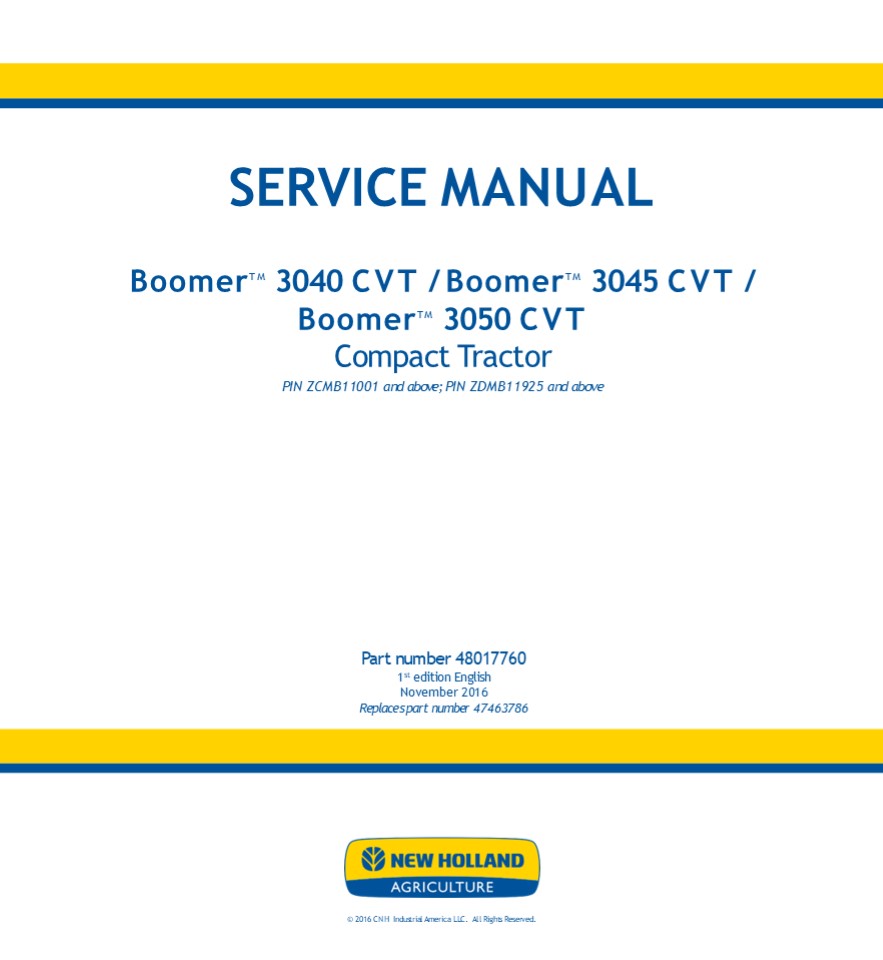
SERVICE MANUAL
BoomerTM
3040 CVT / BoomerTM 3045 CVT / BoomerTM 3050
CVT Compact Tractor PIN ZCMB11001 and above PIN
ZDMB11925 and above
Part number 48017760 1st edition English
November 2016 Replaces part number 47463786
2016 CNH Industrial America LLC. All Rights
Reserved.
2
SERVICE MANUAL Boomer 3040 CVT ZCMB11001 - ,
Boomer 3040 CVT ZDMB11925 - , Boomer 3045
CVT ZCMB11001 - , Boomer 3045 CVT ZDMB11925
- , Boomer 3050 CVT ZCMB11001 - , Boomer
3050 CVT ZDMB11925 -
48017760 14/11/2016
EN
3
Link Product / Engine
Product Market Product Engine
Boomer 3040 CVT ZCMB11001 - Europe N844
Boomer 3040 CVT ZDMB11925 - Europe N844
Boomer 3045 CVT ZCMB11001 - Europe N844L
Boomer 3045 CVT ZDMB11925 - Europe N844L
Boomer 3050 CVT ZCMB11001 - Europe N844L
Boomer 3050 CVT ZDMB11925 - Europe N844L
48017760 14/11/2016
4
https//www.ebooklibonline.com Hello dear
friend! Thank you very much for reading. Enter
the link into your browser. The full manual is
available for immediate download. https//www.eb
ooklibonline.com
5
Contents INTRODUCTION Engine.....................
..................................................
................ 10 10.001 Engine and
crankcase . . . . . . . . . . . . . . . . . . . .
. . . . . . . . . . . . . . . . . . . . . . . . .
. . . . . . . . . . . . . . . . 10.1 10.101
Cylinder heads . . . . . . . . . . . . . . . . .
. . . . . . . . . . . . . . . . . . . . . . . . .
. . . . . . . . . . . . . . . . . . . . . . . . .
. . 10.2 10.102 Pan and covers . . . . . . . .
. . . . . . . . . . . . . . . . . . . . . . . . .
. . . . . . . . . . . . . . . . . . . . . . . . .
. . . . . . . . . . 10.3 10.103 Crankshaft and
flywheel. . . . . . . . . . . . . . . . . . . . .
. . . . . . . . . . . . . . . . . . . . . . . . .
. . . . . . . . . . . . . . 10.4 10.105
Connecting rods and pistons . . . . . . . . . . .
. . . . . . . . . . . . . . . . . . . . . . . . .
. . . . . . . . . . . . . . . . . . .
10.5 10.106 Valve drive and gears . . . . . . .
. . . . . . . . . . . . . . . . . . . . . . . . .
. . . . . . . . . . . . . . . . . . . . . . . . .
. . . . . 10.6 10.110 Balancer and damper . . .
. . . . . . . . . . . . . . . . . . . . . . . . .
. . . . . . . . . . . . . . . . . . . . . . . . .
. . . . . . . . . 10.7 10.114 Pump drives . . .
. . . . . . . . . . . . . . . . . . . . . . . . .
. . . . . . . . . . . . . . . . . . . . . . . . .
. . . . . . . . . . . . . . . . . . .
10.8 10.218 Fuel injection system. . . . . . .
. . . . . . . . . . . . . . . . . . . . . . . . .
. . . . . . . . . . . . . . . . . . . . . . . . .
. . . . . . 10.9 10.254 Intake and exhaust
manifolds and muffler . . . . . . . . . . . . . .
. . . . . . . . . . . . . . . . . . . . . . . . .
10.10 10.304 Engine lubrication system . . . .
. . . . . . . . . . . . . . . . . . . . . . . . .
. . . . . . . . . . . . . . . . . . . . . . . . .
. . 10.11 10.400 Engine cooling system . . . .
. . . . . . . . . . . . . . . . . . . . . . . . .
. . . . . . . . . . . . . . . . . . . . . . . . .
. . . . . 10.12 10.414 Fan and drive . . . . .
. . . . . . . . . . . . . . . . . . . . . . . . .
. . . . . . . . . . . . . . . . . . . . . . . . .
. . . . . . . . . . . . . 10.13 Transmission......
..................................................
...................... 21 21.504 Continuously
Variable Transmission (CVT) . . . . . . . . . . .
. . . . . . . . . . . . . . . . . . . . . . . . .
. . . . 21.1 Four-Wheel Drive (4WD) system
..................................................
23 23.101 Mechanical control . . . . . . . .
. . . . . . . . . . . . . . . . . . . . . . . . .
. . . . . . . . . . . . . . . . . . . . . . . . .
. . . . . . . 23.1 Front axle system
..................................................
..................... 25 25.100 Powered front
axle . . . . . . . . . . . . . . . . . . . . . .
. . . . . . . . . . . . . . . . . . . . . . . . .
. . . . . . . . . . . . . . . . . . 25.1 25.102
Front bevel gear set and differential . . . . . .
. . . . . . . . . . . . . . . . . . . . . . . . .
. . . . . . . . . . . . . . . . 25.2 25.310
Final drives . . . . . . . . . . . . . . . . . .
. . . . . . . . . . . . . . . . . . . . . . . . .
. . . . . . . . . . . . . . . . . . . . . . . . .
. . . . . 25.3 Rear axle system...................
..................................................
... 27 27.100 Powered rear axle. . . . . . . .
. . . . . . . . . . . . . . . . . . . . . . . . .
. . . . . . . . . . . . . . . . . . . . . . . . .
. . . . . . . . 27.1 27.106 Rear bevel gear set
and differential . . . . . . . . . . . . . . . .
. . . . . . . . . . . . . . . . . . . . . . . . .
. . . . . . . 27.2
48017760 14/11/2016
6
Power Take-Off (PTO) .............................
.................................... 31 31.104
Rear electro-hydraulic control . . . . . . . . .
. . . . . . . . . . . . . . . . . . . . . . . . .
. . . . . . . . . . . . . . . . . . . .
31.1 31.110 One-speed rear Power Take-Off (PTO)
. . . . . . . . . . . . . . . . . . . . . . . . .
. . . . . . . . . . . . . . . . . . .
31.2 31.120 Central Power Take-Off (PTO) . . .
. . . . . . . . . . . . . . . . . . . . . . . . .
. . . . . . . . . . . . . . . . . . . . . . . . .
31.3 Brakes and controls .........................
...........................................
33 33.110 Parking brake or parking lock . . . .
. . . . . . . . . . . . . . . . . . . . . . . . .
. . . . . . . . . . . . . . . . . . . . . . . . .
33.1 33.120 Mechanical service brakes . . . . .
. . . . . . . . . . . . . . . . . . . . . . . . .
. . . . . . . . . . . . . . . . . . . . . . . . .
. . 33.2 Hydraulic systems........................
...............................................
35 35.000 Hydraulic systems. . . . . . . . . .
. . . . . . . . . . . . . . . . . . . . . . . . .
. . . . . . . . . . . . . . . . . . . . . . . . .
. . . . . . 35.1 35.104 Fixed displacement pump
. . . . . . . . . . . . . . . . . . . . . . . . .
. . . . . . . . . . . . . . . . . . . . . . . . .
. . . . . . . . 35.2 35.204 Remote control
valves . . . . . . . . . . . . . . . . . . . . .
. . . . . . . . . . . . . . . . . . . . . . . . .
. . . . . . . . . . . . . . . 35.3 35.300
Reservoir, cooler, and filters. . . . . . . . . .
. . . . . . . . . . . . . . . . . . . . . . . . .
. . . . . . . . . . . . . . . . . . . . .
35.4 Steering.....................................
................................................
41 41.200 Hydraulic control components. . . . .
. . . . . . . . . . . . . . . . . . . . . . . . .
. . . . . . . . . . . . . . . . . . . . . . . .
41.1 41.206 Pump . . . . . . . . . . . . . . .
. . . . . . . . . . . . . . . . . . . . . . . . .
. . . . . . . . . . . . . . . . . . . . . . . . .
. . . . . . . . . . . . . . 41.2 41.216
Cylinders . . . . . . . . . . . . . . . . . . . .
. . . . . . . . . . . . . . . . . . . . . . . . .
. . . . . . . . . . . . . . . . . . . . . . . . .
. . . . . 41.3 Cab climate control
..................................................
................... 50 50.100 Heating . . . .
. . . . . . . . . . . . . . . . . . . . . . . . .
. . . . . . . . . . . . . . . . . . . . . . . . .
. . . . . . . . . . . . . . . . . . . . . . .
50.1 50.104 Ventilation . . . . . . . . . . . .
. . . . . . . . . . . . . . . . . . . . . . . . .
. . . . . . . . . . . . . . . . . . . . . . . . .
. . . . . . . . . . . . 50.2 50.200 Air
conditioning. . . . . . . . . . . . . . . . . . .
. . . . . . . . . . . . . . . . . . . . . . . . .
. . . . . . . . . . . . . . . . . . . . . . . . .
50.3 Electrical systems...........................
............................................
55 55.000 Electrical system . . . . . . . . . .
. . . . . . . . . . . . . . . . . . . . . . . . .
. . . . . . . . . . . . . . . . . . . . . . . . .
. . . . . . . 55.1 55.010 Fuel injection
system. . . . . . . . . . . . . . . . . . . . . .
. . . . . . . . . . . . . . . . . . . . . . . . .
. . . . . . . . . . . . . . . . 55.2 55.100
Harnesses and connectors. . . . . . . . . . . . .
. . . . . . . . . . . . . . . . . . . . . . . . .
. . . . . . . . . . . . . . . . . . .
55.3 55.201 Engine starting system . . . . . .
. . . . . . . . . . . . . . . . . . . . . . . . .
. . . . . . . . . . . . . . . . . . . . . . . . .
. . . . . 55.4 55.301 Alternator. . . . . . . .
. . . . . . . . . . . . . . . . . . . . . . . . .
. . . . . . . . . . . . . . . . . . . . . . . . .
. . . . . . . . . . . . . . . . . 55.5 55.302
Battery. . . . . . . . . . . . . . . . . . . . .
. . . . . . . . . . . . . . . . . . . . . . . . .
. . . . . . . . . . . . . . . . . . . . . . . . .
. . . . . . . 55.6 55.404 External lighting . .
. . . . . . . . . . . . . . . . . . . . . . . . .
. . . . . . . . . . . . . . . . . . . . . . . . .
. . . . . . . . . . . . . . . . 55.7
48017760 14/11/2016
7
55.408 Warning indicators, alarms, and
instruments . . . . . . . . . . . . . . . . . . .
. . . . . . . . . . . . . . . . . . .
55.8 55.518 Wiper and washer system. . . . . .
. . . . . . . . . . . . . . . . . . . . . . . . .
. . . . . . . . . . . . . . . . . . . . . . . . .
. . 55.9 55.640 Electronic modules . . . . . .
. . . . . . . . . . . . . . . . . . . . . . . . .
. . . . . . . . . . . . . . . . . . . . . . . . .
. . . . . . . 55.10 55.DTC FAULT CODES . . . .
. . . . . . . . . . . . . . . . . . . . . . . . .
. . . . . . . . . . . . . . . . . . . . . . . . .
. . . . . . . . . . . . 55.11 Platform, cab,
bodywork, and decals .............................
................ 90 90.100 Engine hood and
panels . . . . . . . . . . . . . . . . . . . . .
. . . . . . . . . . . . . . . . . . . . . . . . .
. . . . . . . . . . . . . 90.1 90.116 Fenders
and guards . . . . . . . . . . . . . . . . . . .
. . . . . . . . . . . . . . . . . . . . . . . . .
. . . . . . . . . . . . . . . . . . . .
90.2 90.124 Pneumatically-adjusted operator
seat. . . . . . . . . . . . . . . . . . . . . . .
. . . . . . . . . . . . . . . . . . . . . . .
90.3 90.150 Cab . . . . . . . . . . . . . . . .
. . . . . . . . . . . . . . . . . . . . . . . . .
. . . . . . . . . . . . . . . . . . . . . . . . .
. . . . . . . . . . . . . . . 90.4 90.151 Cab
interior . . . . . . . . . . . . . . . . . . . .
. . . . . . . . . . . . . . . . . . . . . . . . .
. . . . . . . . . . . . . . . . . . . . . . . . .
. . . 90.5 90.154 Cab doors and hatches . . . .
. . . . . . . . . . . . . . . . . . . . . . . . .
. . . . . . . . . . . . . . . . . . . . . . . . .
. . . . . . 90.6
48017760 14/11/2016
8
INTRODUCTION
48017760 14/11/2016 1
9
INTRODUCTION Foreword - Important notice
regarding equipment servicing All repair and
maintenance work listed in this manual must be
carried out only by qualified dealership
personnel, strictly complying with the
instructions given, and using, whenever possible,
the special tools. Anyone who performs repair and
maintenance operations without complying with the
procedures provided herein shall be responsible
for any subsequent damages. The manufacturer and
all the organizations of its distribution chain,
including - without limitation - national,
regional, or local dealers, reject any
responsibility for damages caused by parts and/or
components not approved by the manu- facturer,
including those used for the servicing or repair
of the product manufactured or marketed by the
manufacturer. In any case, no warranty is given
or attributed on the product manufactured or
marketed by the manufacturer in case of damages
caused by parts and/or components not approved by
the manufacturer. The manufacturer reserves the
right to make improvements in design and changes
in specifications at any time without notice and
without incurring any obligation to install them
on units previously sold. Specifications,
descriptions, and illustrative material herein
are as accurate as known at time of publication
but are subject to change without notice. In case
of questions, refer to your NEW HOLLAND Sales and
Service Networks.
48017760 14/11/2016 3
10
INTRODUCTION
Safety rules
Personal safety This is the safety alert
symbol. It is used to alert you to potential
personal injury hazards. Obey all safety
messages that follow this symbol to avoid
possible death or injury.
Throughout this manual you will find the signal
words DANGER, WARNING, and CAUTION followed by
special in- structions. These precautions are
intended for the personal safety of you and those
working with you. Read and understand all the
safety messages in this manual before you operate
or service the machine.
DANGER indicates a hazardous situation that, if
not avoided, will result in death or serious
injury. WARNING indicates a hazardous situation
that, if not avoided, could result in death or
serious injury. CAUTION indicates a hazardous
situation that, if not avoided, could result in
minor or moderate injury.
FAILURE TO FOLLOW DANGER, WARNING, AND CAUTION
MESSAGES COULD RESULT IN DEATH OR SERIOUS
INJURY. Machine safety NOTICE Notice indicates
a situation that, if not avoided, could result in
machine or property damage. Throughout this
manual you will find the signal word Notice
followed by special instructions to prevent
machine or property damage. The word Notice is
used to address practices not related to personal
safety. Information NOTE Note indicates
additional information that clarifies steps,
procedures, or other information in this
manual. Throughout this manual you will find the
word Note followed by additional information
about a step, procedure, or other information in
the manual. The word Note is not intended to
address personal safety or property damage.
48017760 14/11/2016 5
11
- INTRODUCTION
- Safety rules - Ecology and the environment
- Soil, air, and water quality is important for all
industries and life in general. When legislation
does not yet rule the treatment of some of the
substances that advanced technology requires,
sound judgment should govern the use and
disposal of products of a chemical and
petrochemical nature. - Familiarize yourself with the relative
legislation applicable to your country, and make
sure that you understand this legislation. Where
no legislation exists, obtain information from
suppliers of oils, filters, batteries, fuels,
anti-freeze, cleaning agents, etc., with regard
to the effect of these substances on man and
nature and how to safely store, use, and dispose
of these substances. - Helpful hints
- Avoid the use of cans or other inappropriate
pressurized fuel delivery systems to fill tanks.
Such delivery systems may cause considerable
spillage. - In general, avoid skin contact with all fuels,
oils, acids, solvents, etc. Most of these
products contain substances that may be harmful
to your health. - Modern oils contain additives. Do not burn
contaminated fuels and or waste oils in ordinary
heating systems. - Avoid spillage when you drain fluids such as used
engine coolant mixtures, engine oil, hydraulic
fluid, brake fluid, etc. Do not mix drained
brake fluids or fuels with lubricants. Store all
drained fluids safely until you can dispose of
the fluids in a proper way that complies with all
local legislation and available resources. - Do not allow coolant mixtures to get into the
soil. Collect and dispose of coolant mixtures
properly. - The air-conditioning system contains gases that
should not be released into the atmosphere.
Consult an air-condi- tioning specialist or use
a special extractor to recharge the system
properly. - Repair any leaks or defects in the engine cooling
system or hydraulic system immediately. - Do not increase the pressure in a pressurized
circuit as this may lead to a component failure. - Protect hoses during welding. Penetrating weld
splatter may burn a hole or weaken hoses,
allowing the loss of oils, coolant, etc. - Battery recycling
48017760 14/11/2016 6
12
SERVICE MANUAL Engine Boomer 3040 CVT
ZCMB11001 - , Boomer 3040 CVT ZDMB11925 - ,
Boomer 3045 CVT ZCMB11001 - , Boomer 3045
CVT ZDMB11925 - , Boomer 3050 CVT ZCMB11001
- , Boomer 3050 CVT ZDMB11925 -
48017760 14/11/2016 10
13
Engine - Engine and crankcase
Engine - General specification
Boomer 3040 CVT WE
Boomer 3045 CVT WE
Boomer 3050 CVT WE
Boomer 3040 Boomer 3045 Boomer 3050
Engine Model ISM N844 ISM N844L ISM N844L
Number of Cylinders 4 4 4
Bore x Stroke 84 mm x 90 mm ( 3.31 in x 3.54 in) 84 mm x 100 mm ( 3.31 in x 3.94 in) 84 mm x 100 mm ( 3.31 in x 3.94 in)
Displacement 1995 cm³ ( 121.7 in³) 2216 cm³ ( 135.2 in³) 2216 cm³ ( 135.2 in³)
Compression Ratio 22.51 22.51 22.51
Rated Speed 2600 RPM 2600 RPM 2800 RPM
Muffler Horizontal
Firing Order 1-3-4-2 1-3-4-2 1-3-4-2
Low Idle Speed 1050 RPM 1050 RPM 1050 RPM
Maximum No-Load Speed 2825 RPM 2825 RPM 3025 RPM
Cylinder Arrangement In-Line Vertical In-Line Vertical In-Line Vertical
Valve Arrangement Overhead Overhead Overhead
Compression Pressure at 200 RPM(cylinder speed) 29.4 1.8 bar (427 50 psi) 29.4 1.8 bar (427 50 psi) 29.4 1.8 bar (427 50 psi)
Variation between cylinders
Engine - Torque
Boomer 3040 CVT WE
Boomer 3045 CVT WE
Boomer 3050 CVT WE
Boomer 3040 Boomer 3045 Boomer 3050
Engine Model ISM N844 ISM N844L ISM N844L
TORQUE SPECIFICATION
Connecting Rod Cap Bolts 49 - 54 Nm (36 - 40 lb ft) 49 - 54 Nm (36 - 40 lb ft) 49 - 54 Nm (36 - 40 lb ft)
Main Bearing Retaining Bolts 49 - 54 Nm (36 - 40 lb ft) 49 - 54 Nm (36 - 40 lb ft) 49 - 54 Nm (36 - 40 lb ft)
Relief Valve Assembly 59 - 69 Nm (43 - 51 lb ft) 59 - 69 Nm (43 - 51 lb ft) 59 - 69 Nm (43 - 51 lb ft)
Crankshaft Main Bearing Holder Bolts
Rear Main 25 - 29 Nm (18 - 22 lb ft) 25 - 29 Nm (18 - 22 lb ft) 25 - 29 Nm (18 - 22 lb ft)
Center Mains 49 - 54 Nm (36 - 40 lb ft) 49 - 54 Nm (36 - 40 lb ft) 49 - 54 Nm (36 - 40 lb ft)
Engine Rear Mounting Plate 12 - 17 Nm (9 - 12 lb ft) 12 - 17 Nm (9 - 12 lb ft) 12 - 17 Nm (9 - 12 lb ft)
Flywheel Retaining Bolts 68 - 78 Nm (51 - 58 lb ft) 68 - 78 Nm (51 - 58 lb ft) 68 - 78 Nm (51 - 58 lb ft)
Engine Front Plate 9 - 12 Nm (6 - 9 lb ft) 9 - 12 Nm (6 - 9 lb ft) 9 - 12 Nm (6 - 9 lb ft)
Crankshaft Pulley Nut 274 - 333 Nm (202 - 246 lb ft) 274 - 333 Nm (202 - 246 lb ft) 274 - 333 Nm (202 - 246 lb ft)
Cylinder Head Bolts 98 - 103 Nm (72.3 - 76 lb ft) 98 - 103 Nm (72.3 - 76 lb ft) 98 - 103 Nm (72.3 - 76 lb ft)
Rocker Arm Assembly 27 - 39 Nm (20 - 29 lb ft) 27 - 39 Nm (20 - 29 lb ft) 27 - 39 Nm (20 - 29 lb ft)
Rocker Arm Locknut 11 - 16 Nm (8 - 12 lb ft) 11 - 16 Nm (8 - 12 lb ft) 11 - 16 Nm (8 - 12 lb ft)
Oil Tube Banjo Bolt 9 - 13 Nm (7 - 9 lb ft) 9 - 13 Nm (7 - 9 lb ft) 9 - 13 Nm (7 - 9 lb ft)
Oil Pressure Switch 14 - 20 Nm (10 - 14 lb ft) 14 - 20 Nm (10 - 14 lb ft) 14 - 20 Nm (10 - 14 lb ft)
Rocker Cover Bolts 7 - 12 Nm (6 - 9 lb ft) 7 - 12 Nm (6 - 9 lb ft) 7 - 12 Nm (6 - 9 lb ft)
Glow Plugs 14 - 20 Nm (10 - 14 lb ft) 14 - 20 Nm (10 - 14 lb ft) 14 - 20 Nm (10 - 14 lb ft)
Cooling Fan Bolts 9 - 13 Nm (7 - 9 lb ft) 9 - 13 Nm (7 - 9 lb ft) 9 - 13 Nm (7 - 9 lb ft)
Balancer
Retaining Bolts 49 - 53.9 Nm (36 - 39 lb ft) 49 - 53.9 Nm (36 - 39 lb ft) 49 - 53.9 Nm (36 - 39 lb ft)
48017760 14/11/2016 10.1 10.001 / 3
14
Engine - Engine and crankcase Metric Bolt
Torque Specifications
Coarse Thread Fine Thread Coarse Thread Fine Thread Fine Thread Fine Thread
Bolt Size Grade No. Pitch Torque Pitch Torque
4T 4.9 - 6.9 Nm (3.6 - 5.1 lb ft)
M6 7T 1.0 8.3 - 11.3 Nm (6.1 - 8.3 lb ft)
10T 11.8 - 15.7 Nm (8.7 - 11.6 lb ft)
4T 12.7 - 16.7 Nm (9.4 - 12.3 lb ft) 15.2 - 20.1 Nm (11.2 - 14.8 lb ft)
M8 7T 1.25 22.6 - 28.4 Nm (16.6 - 21.0 lb ft) 1.0 26.5 - 34.3 Nm (19.5 - 25.3 lb ft)
10T 28.4 - 36.3 Nm (21.0 - 26.8 lb ft) 30.4 - 40.2 Nm (22.4 - 29.7 lb ft)
4T 25.5 - 33.3 Nm (18.8 - 24.6 lb ft) 28.4 - 36.3 Nm (21.0 - 26.8 lb ft)
M10 7T 1.5 44.1 - 55.9 Nm (32.5 - 41.2 lb ft) 1.25 49.0 - 62.8 Nm (36.2 - 46.3 lb ft)
10T 53.9 - 69.6 Nm (39.8 - 51.4 lb ft) 57.9 - 73.5 Nm (42.7 - 54.2 lb ft)
4T 37.3 - 47.1 Nm (27.5 - 34.7 lb ft) 43.1 - 54.9 Nm (31.8 - 40.5 lb ft)
M12 7T 1.75 65.7 - 83.4 Nm (48.5 - 61.5 lb ft) 1.25 74.5 - 94.1 Nm (55.0 - 69.4 lb ft)
10T 92.2 - 116 Nm (68.0 - 85.4 lb ft) 99.0 - 127 Nm (73.1 - 93.3 lb ft)
4T 62.8 - 80.4 Nm (46.3 - 59.3 lb ft) 69.6 - 87.3 Nm (51.4 - 64.4 lb ft)
M14 7T 2.0 104 - 131 Nm (76.7 - 96.9 lb ft) 1.5 117 - 148 Nm (86.1 - 109 lb ft)
11T 139 - 175 Nm (102 - 129 lb ft) 147 - 186 Nm (108 - 137 lb ft)
4T 86.3 - 110 Nm (63.6 - 81.0 lb ft) 91.2 - 115 Nm (67.3 - 84.6 lb ft)
M16 7T 2.0 140 - 184 Nm (110 - 136 lb ft) 1.5 157 - 192 Nm (116 - 142 lb ft)
11T 206 - 255 Nm (152 - 188 lb ft) 221 - 270 Nm (163 - 199 lb ft)
4T 114 - 141 Nm (83.9 - 104 lb ft) 131 - 163 Nm (96.9 - 120 lb ft)
M18 7T 2.0 196 - 235 Nm (145 - 174 lb ft) 1.5 230 - 279 Nm (170 - 206 lb ft)
11T 275 - 333 Nm (203 - 246 lb ft) 299 - 368 Nm (221 - 271 lb ft)
4T 144 - 179 Nm (106 - 132 lb ft) 172 - 211 Nm (127 - 156 lb ft)
M20 7T 2.5 240 - 289 Nm (177 - 213 lb ft) 1.5 275 - 333 Nm (203 - 246 lb ft)
11T 363 - 441 Nm (268 - 325 lb ft) 397 - 485 Nm (293 - 358 lb ft)
Engine - Special tools
Boomer 3040 CVT WE
Boomer 3045 CVT WE
Boomer 3050 CVT WE
48017760 14/11/2016 10.1 10.001 / 4
15
Engine - Cylinder heads
Cylinder head - Static description
Boomer 3040 CVT WE
Boomer 3045 CVT WE
Boomer 3050 CVT WE
Cylinder Head and Valve Train Components The
cylinder head incorporates the valve assemblies,
rocker arms, rocker shaft, push rods, and
lifters. A swirl cham- ber located between the
injector assembly and the main combustion chamber
of the cylinders provides improved starting and
greater fuel efficiency. Initial combustion
starts in the precombustion chamber and as the
expansion oc- curs a strong swirl pattern is
created in the main combustion chamber for more
complete combustion of the air-fuel mixture. The
air intake manifold is separate from the cast
aluminum valve cover on all these engines. The
exhaust manifold is bolted on the left-hand side
of the cylinder head on each of the models.
Cylinder heads have integral valve guides.
Standard size valves only are used. The cylinder
block assembly contains the pistons, connecting
rods, crankshaft, timing gears, and engine oil
pump. The crankshaft is supported on five main
bearings. The front bearing is positioned in a
bore in front of the block. The other bearings
are split liners located in holders bolted to the
block. The camshaft is supported on four ball
bearings located in the block.
7607624950 1 Engine models ISM N844 and ISM
N844L
48017760 14/11/2016 10.2 10.101 / 4
16
Engine - Cylinder heads
Valve cover - Install
Boomer 3040 CVT WE
Boomer 3045 CVT WE
Boomer 3050 CVT WE
- Prior operation
- Valve drive and gears - Clearance (Valves)
(10.106). - Install a new gasket (1) and position the valve
cover (2) - over the rocker arms.
- Install the valve cover retaining bolts (3), and
tighten to - 12 - 16 Nm (9 - 19 lb ft).
- Install and tighten the seal washer (4), and cap
nuts (5).
76075733A 1
Next operation Water pump - Install (with
Cooling Fan) (10.400).
48017760 14/11/2016 10.2 10.101 / 5
17
Engine - Cylinder heads
Cylinder head - Compression test
Boomer 3040 CVT WE
Boomer 3045 CVT WE
Boomer 3050 CVT WE
- Compression test is performed through the glow
plug ports. The test adapter tool (1), is
equipped with quick coupler ends for easy
installation of the hose and gauge. - The procedures to perform a compression test are
as follows - Remove the wire lead from the fuel injection pump
so- lenoid. - Remove the glow plug electrical wire and wire
connec- tor from top of the glow plugs.
SECT10C01PG17_1 1
- Remove all of the glow plugs.
- NOTE Be sure all the glow plugs are removed
before starting the compression tests. - Install the adapter Tool No. FNH00120 , hose and
gauge assembly OEM1074 (2), in each port and
crank the engine until pressure stabilizes. The
gauge should read 2944 kPa (427 psi) ) plus or
minus 345 kPa (50 psi) .
SECT10C01PG17_2 2
NOTE It may be necessary to remove some injector
fuel lines to install the adapter tool. NOTE
There should not be more than 345 kPa (50 psi)
variation between the cylinders. 5. When all
cylinders have been tested, reinstall the glow
plugs and electrical connections.
48017760 14/11/2016 10.2 10.101 / 6
18
Suggest If the above button click is invalid.
Please download this document first, and then
click the above link to download the complete
manual. Thank you so much for reading
19
Engine - Cylinder heads
Cylinder head - Remove
Boomer 3040 CVT WE
Boomer 3045 CVT WE
Boomer 3050 CVT WE
- Prior operation
- Rocker Arm Shaft and Support Bracket - Remove
See Engine Disassemble.. - Remove the valve stem caps (1), and push rods
(2). - To remove the cylinder head, remove the cylinder
head bolts (3), by alternately loosening a half
turn at a time to prevent warping the head. - NOTE Keep all valve components in separately
marked containers for reassembly in their
original location.
20093361A 1
Next operation Valve Tappet - Removal See
Engine Disassemble.
48017760 14/11/2016 10.2 10.101 / 7
20
https//www.ebooklibonline.com Hello dear
friend! Thank you very much for reading. Enter
the link into your browser. The full manual is
available for immediate download. https//www.eb
ooklibonline.com
Recommended

