
New Holland TT55 Tractor Service Repair Manual Instant Download PowerPoint PPT Presentation
Title: New Holland TT55 Tractor Service Repair Manual Instant Download
1
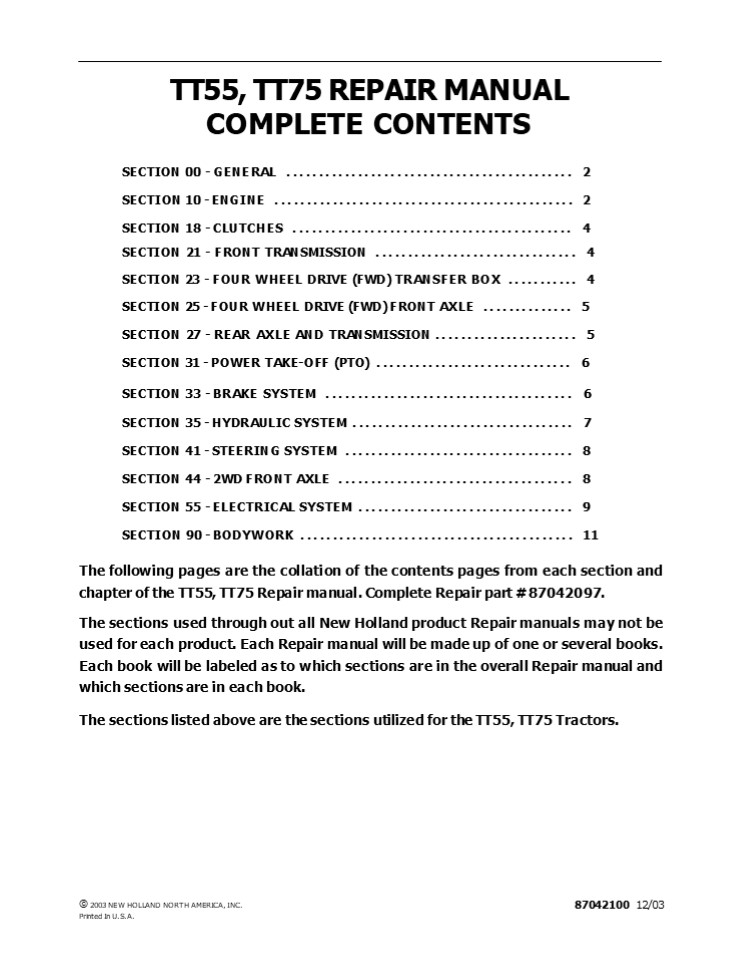
TT55, TT75 REPAIR MANUAL COMPLETE CONTENTS
- SECTION 00 - GENERAL .............................
............... 2 - SECTION 10 - ENGINE ..............................
................ 2 - SECTION 18 - CLUTCHES ............................
............... 4 - SECTION 21 - FRONT TRANSMISSION
............................... 4 SECTION 23 -
FOUR WHEEL DRIVE (FWD) TRANSFER BOX ........... 4
SECTION 25 - FOUR WHEEL DRIVE (FWD) FRONT AXLE
.............. 5 - SECTION 27 - REAR AXLE AND TRANSMISSION
...................... 5 SECTION 31 - POWER
TAKE-OFF (PTO) .............................. 6 - SECTION 33 - BRAKE SYSTEM ........................
.............. 6 - SECTION 35 - HYDRAULIC SYSTEM ....................
.............. 7 - SECTION 41 - STEERING SYSTEM .....................
.............. 8 - SECTION 44 - 2WD FRONT AXLE ......................
.............. 8 - SECTION 55 - ELECTRICAL SYSTEM ...................
.............. 9 - SECTION 90 - BODYWORK ............................
.............. 11 - The following pages are the collation of the
contents pages from each section and chapter of
the TT55, TT75 Repair manual. Complete Repair
part 87042097. - The sections used through out all New Holland
product Repair manuals may not be used for each
product. Each Repair manual will be made up of
one or several books. Each book will be labeled
as to which sections are in the overall Repair
manual and which sections are in each book. - The sections listed above are the sections
utilized for the TT55, TT75 Tractors.
? 2003 NEW HOLLAND NORTH AMERICA, INC. Printed In
U.S.A.
87042100 12/03
2
SECTION 00 - GENERAL - CHAPTER 1 SECTION 00 -
GENERAL Chapter 1 - General CONTENTS
Description Page General Instructions
..................................................
.......... 3 Health and Safety ...................
.......................................
5 Precautionary Statements .......................
.......................... 15 Safety
..................................................
................ 16 Ecology and the Environment
..............................................
19 General Specifications ........................
................................ 20 Minimum
Hardware Tightening Torques ......................
............... 24 Tractor System Components
...............................................
26 Speed Chart ...................................
.......................... 29 Federal Emissions
Warranty .........................................
...... 31
Section
3
SECTION 00 - GENERAL - CHAPTER 1 WARNING WARNING
All maintenance and repair work described in this
manual must be performed exclusively by NEW
HOLLAND service technicians in strict accordance
with the instructions given and using any
specific tools necessary.
The Manufacturer and all organizations belong-
ing to the Manufacturer's distribution network,
including but not restricted to national,
regional or local distributors, will accept no
responsibility for personal injury or damage to
property caused by abnormal function of parts
and/or compo- nents not approved by the
Manufacturer, including those used for
maintenance and/or repair of the product
manufactured or marketed by the Manufacturer. In
any case, the product manufactured or marketed by
the Manufacturer is covered by no guarantee of
any kind against personal injury or damage to
property caused by abnormal function of parts
and/or components not approved by the
Manufacturer.
WARNING
Anyone who performs the operations described
herein without strictly following the
instructions is personally responsible for
resulting injury or damage to property.
4
https//www.ebooklibonline.com Hello dear
friend! Thank you very much for reading. Enter
the link into your browser. The full manual is
available for immediate download. https//www.ebo
oklibonline.com
5
SECTION 00 - GENERAL - CHAPTER 1 GENERAL
INSTRUCTIONS
IMPORTANT NOTICE All maintenance and repair
operations described in this manual should be
carried out exclusively by the authorised
workshops. All instructions detailed should be
carefully observed and special equipment
indicated should be used if necessary. Everyone
who carries out service operations described
without carefully observing these prescrip- tions
will be directly responsible of deriving
damages.
- Take care to insert the seal perpendicularly to
its seat while you are pressing it. Once the seal
is settled, ensure that it contacts the thrust
element, if required - To prevent damaging the sealing lip against the
shaft, place a suitable protection during
installation.
O RINGS Lubricate the O rings before inserting
them into their seats. This will prevent the O
rings from roll over and twisting during
mounting, which will jeopardize sealing.
SHIMMING At each adjustment, select adjusting
shims, measure them individually using a
micrometer and then sum up recorded values. Do
not rely on measuring the whole shimming set,
which may be incorrect, or on the rated value
indicated for each shim.
SEALERS Apply silicone/gasket eliminator over the
mating surfaces marked with an X. Before applying
the sealer, prepare the surface as follows
ROTATING SHAFT SEALS To correctly install
rotating shaft seals, observe the following
instructions
- remove possible scales using a metal brush
- thoroughly degrease the surfaces using one of the
following cleaning agents trichlorethylene,
diesel fuel or a water and soda solution.
- Let the seal soak into the same oil as it will
seal for at least half an hour before mounting - Thoroughly clean the shaft and ensure that the
shaft working surface is not damaged - Place the sealing lip towards the fluid. In case
of a hydrodynamic lip, consider the shaft
rotation direction and orient grooves in order
that they deviate the fluid towards the inner
side of the seal - Coat the sealing lip with a thin layer of
lubricant (oil rather than grease) and fill the
gap between the sealing lip and the dust lip of
double lip seals with grease - Insert the seal into its seat and press it down
using a flat punch. Do not tap the seal with a
hammer or a drift
BEARINGS It is advisable to heat the bearings to
80? to 90?C (176? to 194?F) before mounting them
on their shafts and cool them down before
inserting them into their seats with external
tapping.
SPRING PINS When mounting split socket spring
pins, ensure that the pin notch is oriented in
the direction of the effort to stress the
pin. Spiral spring pins should not be oriented
during installation.
6
- SECTION 00 - GENERAL - CHAPTER 1
- GENERAL INSTRUCTIONS
- PRECAUTIONARY NOTICE
- Only authorized workshops should carry out
maintenance and repair operations on the tractor,
or tractor compo- nents. Carefully observe all
instructions, safety precautions, and the use of
equipment such as special tools, as detailed in
this manual. Damage to the tractor, or injury to
personnel is the direct responsibility of anyone
who fails to observe these precautions. - EQUIPMENT NOTICE
- The equipment proposed in this manual is
- Designed and studied expressly for use on New
Holland tractors - Necessary for adequate and reliable repair of the
tractor - Strictly tested for the efficient and long
lasting life cycle of the tractor - SPARE PARTS NOTICE
- Genuine NEW HOLLAND spare parts guarantee the
same quality, safety and life cycle as original
components. These parts bear the logo
GENERAL NOTICES In this manual, the description
FRONT, REAR, RIGHT -HAND and LEFT -HAND
refer to the view seen by the operator while in
the operators seat, looking in the direction in
which the tractor normally moves. Wear limits
detailed in this manual, although advised, are
not binding.
7
SECTION 10 - ENGINE - CHAPTER 1 SECTION 10 -
ENGINE Chapter 1 - Engine Overhaul CONTENTS
Description Page General Specifications
..................................................
........ 2 Tightening Torque Data
..................................................
.. 13 Engine Special Tools .......................
............................... 14 Engine
Sectional Views ..................................
.................. 16 Engine Removal
..................................................
........... 23 Splitting the tractor
..................................................
...... 24 Engine Reinstallation
..................................................
....... 25 Engine Disassembly ....................
...................................... 27 Engine
Assembly ........................................
.................... 45 Checks, Dimensions and
Repairs ..........................................
..... 58 Cylinder Block and Cylinder Liners
..........................................
58 Crankshaft, Main Bearings and Flywheel
..................................... 60
Connecting Rod ...................................
....................... 65 Pistons
..................................................
................ 66 Camshaft, Tappets and Valves
..............................................
69 Cylinder Head .................................
........................... 72 Valve Guide
Replacement ......................................
............ 73 Valve Seat In Cylinder Head
Refacing .......................................
77 Injector Sleeve Replacement ...................
............................ 78 Rotating
Counterweight Dynamic Balancer ...................
................ 80 Engine Lubrication System
Overhaul .........................................
... 81 Crankshaft Front Oil Seal
Removal/Installation .............................
...... 83 Coolant System Overhaul
..................................................
... 87 Fuel System Overhaul ......................
.................................. 93 Valve
Clearance Adjustment .............................
..................... 104 Engine Testing
..................................................
............ 108
Section
8
SECTION 10 - ENGINE - CHAPTER 1 GENERAL
SPECIFICATIONS
ENGINE SPECIFICATIONS TT55 TT75
Engine 55 hp naturally aspirated 8035 - 06 - 507 (w/BOSCH pump emiss) 70 hp naturally aspirated 8045 - 06 - 506 (w/BOSCH pump emiss)
Cycle 4-stroke diesel 4-stroke diesel
Fuel Injection Direct Direct
Number of Cylinders 3 cylinders 4 cylinders
Cylinder Liners Dry, force-fitted on engine block Dry, force-fitted on engine block
Bore (Piston Diameter) 100 mm (3.9370 in.) 100 mm (3.9370 in.)
Stroke 115 mm (4.5276 in.) 115 mm (4.5276 in.)
Total Displacement 2710 cm3 (165 in.3) 3613 cm3 (220 in.3)
Compression Ratio 17 to 1 ratio 17 to 1 ratio
Maximum Power 40.5 kW (55 hp) 55.5 kW (70 hp)
Maximum Output Speed 2500 RPM 2500 RPM
Maximum Torque Speed 1500 RPM 1400 RPM
Idle Speed 650 700 RPM 650 700 RPM
Main Bearings 4 5
Sump Structural, in cast iron Structural, in cast iron
Balancer Flyweight, engine sump
9
SECTION 10 - ENGINE - CHAPTER 1 ENGINE
REMOVAL DANGER Lift and handle all heavy parts
using suitable lifting equipment. Ensure to
support load by means of suitable slings and
hooks. Ensure no-one is standing in the vicinity
of the load to when lifting.
CAUTION
1 40035227
Always use suitable tools to align holes in
parts. NEVER USE YOUR FINGERS OR HANDS.
- Before removing engine
- Disconnect the negative lead (1), from the
battery. - Drain oil from the transmission/gearbox.
- Drain liquid from cooling system.
11
On FWD Models
1 2 25039
1. Remove the circlip (2), and slide the sleeve
(1) in the direction shown by the arrow until
free of the splines on the front axle.
12
2. Remove the circlip (2) and slide the sleeve
(1) in the direction shown by the arrow until it
is free of the spines on the drive shaft.
1 2 25040
13
10
SECTION 10 - ENGINE - CHAPTER 1
3. Remove the retaining bolts from the central
drive shaft support (1) and remove the shaft
complete with support.
1 25041
14
Splitting the tractor
1
- Disconnect the negative battery lead if not
previously done. - Place wedges between the front axle and the
front axle carries to prevent the assembly from
tilting. - Disconnect the tractor electrical harnesses.
- Remove the exhaust pipe and right and left
middle hood sections. - Remove the steering lines tubes.
- Remove the suction line from the hydraulic
reservoir and cap the reservoir port. - Remove the throttle linkage (1) from the
injection pump and from the mounting point under
rear hood. - Disconnect the fuel delivery line from the primer
pump and the return line from the tee. - Remove bolts holding Fire Wall to engine.
40035234
15
- Remove the hydraulic lift suction and delivery
lines from the hydraulic pump. - If there is a horizontal exhaust, disconnect or
remove exhaust line and muffler. - On four-wheel drive tractors, disconnect and
drop the front axle driveshaft. - Place a hydraulic stand under the clutch
transmission case and attach lifting tackle to
the engine. - Unbolt the engine from the transmission case.
- Using a crane, separate the engine from the rest
of the tractor.
11
SECTION 10 - ENGINE - CHAPTER 1 16. Insert
centralizer tool (1) 380000612 in the clutch
center hole. Unscrew the six bolts securing the
clutch to the flywheel and remove complete clutch
assembly.
1
2
25057
- 16
- Attach the adjustable lifting chain to the
eyebolts on the engine. - Place wooden wedges under the rear wheels, check
that the handbrake is fully on and that the fixed
and moving stands are firmly in place. - The next operation will require 2 or 3
operatives. Position the engine/front axle unit
up to the clutch housing, pushing the front
wheels and accompanying the unit with the hoist.
Be careful at this stage not to damage the rigid
hydraulic oil pipes. Make sure that no electrical
leads are trapped between the two units. - Next, turn the cooling fan to rotate the clutch
disc so it engages with the two shafts of the PTO
and transmission. - Replace and tighten all the bolts securing the
engine to the clutch housing. - Lower the stands under the engine sump and the
clutch housing. - Connect the injector leak-off pipe. Connect the
pipes to the glowplug and to the fuel water
separator filter. - Install the fuel filter mounting to the engine.
Connect the two semi-rigid pipes to the mounting. - Connect the power steering at control valve oil
supply and return pipes. - Connect the hydraulic oil suction pipe to the
pump.
ENGINE REINSTALLATION To re-install the engine,
proceed as follows
- Attach the three hooks of an adjustable lifting
chain to three eye bolts on the engine. Raise the
engine from the platform and position it in front
of the front axle support. Join the two units
using the four securing bolts. - Move a rolling jack under the engine sump.
- Drive wedge blocks between front axle carrier
casting and front axle housing. - Attach the top radiator hose to the thermostat
housing and secure with adjustable hose
clamps. - Connect the bottom radiator hose to the coolant
pump and secure at both ends with adjustable hose
clamps. - Install the hydraulic pumps.
- Detach the lifting chain from the engine.
- Connect the rigid pipe from the air cleaner to
the inlet manifold and secure with the relative
clamp. - Reconnect all electrical leads thermostarter
glow plug, coolant temperature sensor, air filter
clogging sensor, horn, front axle support ground,
engine stop on injection pump, leads to the
alternator and relay, oil pressure sensor, and
starter motor. Secure all leads with plastic
ties. - Install the clutch using tool 380000612. Fix
clutch to the engine flywheel using the six
retaining bolts.
12
SECTION 10 - ENGINE - CHAPTER 1
- Connect the rigid lift control valve supply pipe
to the hydraulic pump, remembering to first fit
the O-ring. - Secure the two pipes with the adjustable hose
clamp. - Connect up all the electrical leads to the
connectors.
- Reinstall the 4WD transmission shaft and the
guard. - Re-connect the throttle rod to the accelerator
mechanism. - Replace the fan guards.
- Reinstall the front ballast and secure with the
lock pin. - Fill the transmission/gearbox/power steering
bottle with oil. - Fill the radiator with coolant mixture.
- Connect the positive and negative battery leads.
- Connect the two flexible power steering pipes to
the union on the right-hand side of the front
axle. Secure the two pipes with a special clamp
and fix the clamp to the tractor with a screw. - Install the tachometer cable and secure the
sleeve with the retaining ring.
13
SECTION 10 - ENGINE - CHAPTER 1 ENGINE -
Disassembly CAUTION Handle all parts carefully.
Do not put your hands or fingers between
parts. Wear suitable safety clothing - safety
goggles, gloves and shoes. After removing all
relative guards, shields and parts mounted to the
engine in the tractor and the engine is free
proceed as follows
- Loosen the alternator pivot bolt.
- Loosen the belt tension adjustment bolt (1).
- Release the belt tension adjustment arm by
undoing the retaining nut. - Remove the alternator and coolant pump drive
belt.
1 25072
17
5. Unscrew the bolts securing the fan (1) and
pulley to the coolant pump and remove the fan and
pulley.
1 25073
18
6. Remove the union in order to gain access to
the pump retaining bolt.
1 25077
19
14
SECTION 10 - ENGINE - CHAPTER 1
7. Unscrew the coolant pump retaining bolts (1)
and remove the pump.
1 25076
20
8. Unscrew the pump support bolts (1), the
internal support bolt and remove the support.
1
25078
21
9. Loosen the alternator support retaining bolts
(1) and remove the complete alternator assembly.
1 25081
22
15
SECTION 10 - ENGINE - CHAPTER 1
10. Unscrew the bolts (1) securing the exhaust
manifold to the cylinder head and remove the
manifold.
1 25082
23
11. Remove the thermostat housing retaining
bolts (1) and remove the thermostat housing.
1 25084
24
12. Unscrew the high pressure fuel line unions
(1) on the injection pump and remove the fuel
lines.
1
25085
25
16
SECTION 10 - ENGINE - CHAPTER 1
13. Unscrew the bolts (1) securing the inlet
manifold to the cylinder head and remove the
manifold.
1 25086
26
14. Unscrew the unions (1) on the fuel supply
pump and detach the fuel lines.
1 25087
27
17
SECTION 10 - ENGINE - CHAPTER 1
15. Loosen screws (1) and remove the injection
pump drive gear cover.
1 25089
28
16. Unscrew the nuts (1) securing the injection
pump to the timing gear case.
1
25088
29
17. Unscrew the nut (1) securing the injection
pump shaft to the drive gear.
1 25090
30
18
Suggest If the above button click is invalid.
Please download this document first, and then
click the above link to download the complete
manual. Thank you so much for reading
19
SECTION 10 - ENGINE - CHAPTER 1
18. Remove the injection pump drive gear using
tool 380000835 (1) and recover the injection pump
and the woodruff key.
1 25091
31
19. Disconnect the fuel line unions (1) on the
fuel filter.
1
10036159
32
20. Remove the bolts securing the fuel filter
support to the engine block and remove the
complete filter assembly (1).
1
10036159
33
10-32
20
https//www.ebooklibonline.com Hello dear
friend! Thank you very much for reading. Enter
the link into your browser. The full manual is
available for immediate download. https//www.ebo
oklibonline.com
Recommended
