
BOBCAT 325 COMPACT EXCAVATOR Service Repair Manual Instant Download (SN 514013001 & Above)
Title:
BOBCAT 325 COMPACT EXCAVATOR Service Repair Manual Instant Download (SN 514013001 & Above)
Description:
BOBCAT 325 COMPACT EXCAVATOR Service Repair Manual Instant Download (SN 514013001 & Above) –
Number of Views:0
Title: BOBCAT 325 COMPACT EXCAVATOR Service Repair Manual Instant Download (SN 514013001 & Above)
1
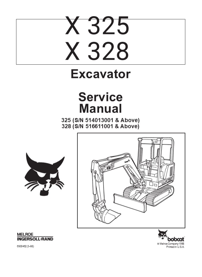
X 325
X 328
Excavator Service Manual 325 (S/N 514013001
Above) 328 (S/N 516611001 Above)
? Melroe Company 1998 Printed in U.S.A.
6900462 (398)
2
MAINTENANCE SAFETY
Instructions are necessary before operating or
servicing machine. Read and understand the
Operation Maintenance Manual, Operators
Handbook and signs (decals) on machine. Follow
warnings and instructions in the manuals when
making repairs, adjustments or servicing. Check
for correct function after adjustments, repairs
or service. Untrained operators and failure to
follow instructions can cause injury or
death. W-2003-0903
WARNING
Safety Alert Symbol This symbol with a warning
statement, means Warning, be alert! Your safety
is involved! Carefully read the message that
follows.
CORRECT B-10731a
CORRECT B-14148
CORRECT B-14142
Use the correct procedure to lift and support
the excavator. Always lift the blade fully before
installing jackstands.
Never service the Hydraulic Excavator
instructions.
Bobcat without
Cleaning and maintenance are required daily.
WRONG B-14147
WRONG B-14141
WRONG B-14145
Have good ventilation when welding or grinding
painted parts. Wear dust mask when grinding
painted parts. Toxic dust and gas can be
produced.
Vent exhaust to outside when engine must be run
for service. Exhaust system must be tightly
sealed. Exhaust Fumes can kill without warning.
Always lower the bucket and blade to the ground
before doing any maintenance. Never modify
equipment or add attachments not approved by
Bobcat Company.
WRONG B-14146
WRONG B-14143
WRONG B-6589
Stop, cool and clean engine of flammable
materials before checking fluids. Never service
or adjust machine with the engine running unless
instructed to do so in the manual.
Keep body, jewelry and clothing away from moving
parts, electrical contact, hot parts and
exhaust. Wear eye protection to guard from
battery acid, compressed springs, fluids under
pressure and flying debris when engines are
running or tools are used. Use eye protection
approved for type of welding. Keep rear door
closed except for service. Close and latch door
before operating the excavator.
Lead-acid batteries produce
flammable and explosive gases.
Keep arcs, sparks, flames and lighted tobacco
away from batteries. Batteries contain acid
which burns eyes or skin on contact. Wear
protective clothing. If acid contacts body,
flush well with water. For eye contact flush
well and get immediate medical attention.
Avoid contact with leaking
hydraulic fluid or diesel fuel
under pressure. It can penetrate the skin or
eyes. Never fill fuel tank with engine running,
while smoking or when near open flame.
Maintenance procedures which are given in the
Operation Maintenance Manual can be performed
by the owner/ operator without any specific
technical training. Maintenance procedures which
are not in the Operation Maintenance Manual
must be performed ONLY BY QUALIFIED BOBCAT
SERVICE PERSONNEL. Always use genuine Bobcat
replacement parts. The Service Safety Training
Course is available from your Bobcat dealer.
MSW20-0805
3
ALPHABETICAL INDEX
ACCUMULATOR . . . . . . . . . . . . . . . . . . .
. . . . . . . . . . . 21 AIR CLEANER . . . . . .
. . . . . . . . . . . . . . . . . . . . . . . . .
. 71 AIR CLEANER SERVICE . . . . . . . . . . .
. . . . . . . . . . . 11 ALTERNATOR . . . . . .
. . . . . . . . . . . . . . . . . . . . . . . . .
. 61 ALTERNATOR BELT . . . . . . . . . . . . . .
. . . . . . . . . . . . 11 ARM BUSHINGS . . . .
. . . . . . . . . . . . . . . . . . . . . . . . .
. 41 ARM CYLINDER . . . . . . . . . . . . . . .
. . . . . . . . . . . . . . . 21 AUXILIARY
SELECTOR VALVE . . . . . . . . . . . . . . . . .
21 BATTERY . . . . . . . . . . . . . . . . . . .
. . . . . . . . . . . . . . . . . 61 BLADE
CYLINDER . . . . . . . . . . . . . . . . . . . .
. . . . . . . . 21 BOOM . . . . . . . . . . . .
. . . . . . . . . . . . . . . . . . . . . . . . .
. . 41 BOOM BUSHING . . . . . . . . . . . . . .
. . . . . . . . . . . . . . . 41 BOOM CYLINDER .
. . . . . . . . . . . . . . . . . . . . . . . . .
. . 21 BOOM CYLINDER SHIELD . . . . . . . . . .
. . . . . . . . . . 21 BOOM SWING BRACKET . . .
. . . . . . . . . . . . . . . . . . 41 BOOM
SWING CYLINDER . . . . . . . . . . . . . . . . .
. . . . 21 BUCKET . . . . . . . . . . . . . . .
. . . . . . . . . . . . . . . . . . . . . .
41 BUCKET CYLINDER . . . . . . . . . . . . . . .
. . . . . . . . . . . 21 BUCKET SPECIFICATIONS .
. . . . . . . . . . . . . . . . . . . 81 BUILD
UP VALVE . . . . . . . . . . . . . . . . . . . .
. . . . . . . . . 21 BUZZER . . . . . . . . . .
. . . . . . . . . . . . . . . . . . . . . . . . .
. . 61 CAB . . . . . . . . . . . . . . . . . .
. . . . . . . . . . . . . . . . . . . . . . . 41
CAB/CANOPY REAR COVER . . . . . . . . . . . . .
. . . . . 41 CAB ELECTRICAL . . . . . . . . . .
. . . . . . . . . . . . . . . . . . 61 CASE
DRAIN FILTER . . . . . . . . . . . . . . . . . .
. . . . . . . 21 CENTER SWIVEL JOINT . . . . . .
. . . . . . . . . . . . . . . . 41 COOLING
SYSTEM . . . . . . . . . . . . . . . . . . . . .
. . . . . . 11 CORNER POST . . . . . . . . . . .
. . . . . . . . . . . . . . . . . . .
41 COUNTERWEIGHTS . . . . . . . . . . . . . . .
. . . . . . . . . . . 41 CRANKSHAFT AND
BEARINGS . . . . . . . . . . . . . . . . 71
CRANKSHAFT GEAR . . . . . . . . . . . . . . . . .
. . . . . . . . 71 CROSS PORT RELIEF VALVE . .
. . . . . . . . . . . . 21, 41 CYLINDER BORE .
. . . . . . . . . . . . . . . . . . . . . . . . .
. . . 71 CYLINDER HEAD . . . . . . . . . . . . .
. . . . . . . . . . . . . . . . 71 DECIMAL AND
MILLIMETER EQUIVALENTS . . . . 81 DIODES (325
S/N 514014900 Above) (328 S/N 516611001
Above) . . . . . . . . . . . . . . . . .
61 ELECTRICAL SYSTEM . . . . . . . . . . . . .
. . . . . . . 11, 61 ENGINE . . . . . . . . .
. . . . . . . . . . . . . . . . . . . . . . . . .
. . . 71 ENGINE COMPRESSION . . . . . . . . . .
. . . . . . . . . . . . 71 ENGINE COVER . . . .
. . . . . . . . . . . . . . . . . . . . . . . . .
. 11 ENGINE FLYWHEEL . . . . . . . . . . . . . .
. . . . . . . . . . . . 71 ENGINE LUBRICATION
SYSTEM . . . . . . . . . . . . . . . 11 ENGINE
OIL AND COOLING SPECIFICATIONS . . 81 ENGINE
SPECIFICATIONS . . . . . . . . . . . . . . . . .
. . . 81 FAN GUARD . . . . . . . . . . . . . .
. . . . . . . . . . . . . . . . . . . 71 FLOOR
MAT AND FLOOR PLATE . . . . . . . . . . . . . .
41 FLYWHEEL RING GEAR . . . . . . . . . . . . .
. . . . . . . . . . 71 FRONT ENGINE COVER . . .
. . . . . . . . . . . . . . . . . . . 41 FUEL
CAMSHAFT . . . . . . . . . . . . . . . . . . . .
. . . . . . . . 71 FUEL, COOLANT AND LUBRICANTS
. . . . . . . . . . . 81 FUEL INJECTOR NOZZLES
. . . . . . . . . . . . . . . . . . . . 71 FUEL
INJECTION PUMP . . . . . . . . . . . . . . . . .
. . . . . 71 FUEL LEVEL SENDER . . . . . . . . .
. . . . . . . . . . . . . . . 61 FUEL SHUTOFF
SOLENOID . . . . . . . . . . . . . . . . . . 71
FUEL SYSTEM . . . . . . . . . . . . . . . . . . .
. . . . . . . . . . . . 11 FUEL TANK . . . . . .
. . . . . . . . . . . . . . . . . . . . . . . . .
. . . 41 GAUGES . . . . . . . . . . . . . . . .
. . . . . . . . . . . . . . . . . . . . 61 GLOW
PLUGS . . . . . . . . . . . . . . . . . . . . . .
. . . . . . . . . . 71 HEATER AIR FILTER
SERVICE . . . . . . . . . . . . . . . . . 11
HORN . . . . . . . . . . . . . . . . . . . . . .
. . . . . . . . . . . . . . . . . 61
HYDRAULIC CONTROL VALVE (5Spool) Boost, Arm,
Boom Swing, Blade and Swing Section . . . . . .
21 HYDRAULIC CONTROL VALVE (5Spool) Left
Travel, Right Travel, Boom, Bucket and Auxiliary
. . . . . . . . . 21 HYDRAULIC CYLINDERS . . .
. . . . . . . . . . . . . . . . . . . . 21
HYDRAULIC EXCAVATOR SPECIFICATIONS (325 S/N
514013001514014899) . . . . . . . . . . . . . .
. 81 HYDRAULIC EXCAVATOR SPECIFICATIONS (325
S/N 514014900 Above) (328 S/N 516611001
Above) . . . . . . . . . . . . . . . . . .
81 HYDRAULIC FILTER ASSEMBLY . . . . . . . . . .
. . . . . . 21 HYDRAULIC PUMP . . . . . . . . .
. . . . . . . . . . . . . . . . . . .
21 HYDRAULIC RESERVOIR . . . . . . . . . . . . .
. . . . . . . . . 21 HYDRAULIC SERVICE
INFORMATION . . . . . . . . . . . 21 HYDRAULIC
SYSTEM . . . . . . . . . . . . . . . . . . . . .
. . . . . 11 HYDRAULIC SYSTEM TROUBLESHOOTING .
. . . . 21 IDLER GEAR AND CAMSHAFT . . . . . .
. . . . . . . . . . . . 71 INSTRUMENT
PANEL (325 S/N 514013001514014899) . . . . . . .
. . . . . . . . 61 JOYSTICK . . . . . . . . . .
. . . . . . . . . . . . . . . . . . . . . . . . .
. 31 JOYSTICK CONTROL CHANGE . . . . . . . . .
. . . . . . . . 21 LEFT CONSOLE (325 S/N
514013001514014899) 31 LEFT CONSOLE (325 S/N
514014900 Above) (328 S/N 516611001 Above)
. . . . . . . . . . . . . . . . . . 31 LEFT
CONSOLE COVER (325 S/N 514014900 Above) (328
S/N 516611001 Above) . . . . . . . . . . . . .
. . . . . 31 LEFT SIDE COVER . . . . . . . . . .
. . . . . . . . . . . . . . . . . . 41 LIFTING
AND BLOCKING THE EXCAVATOR . . . . . . 11
LUBRICATION OF THE EXCAVATOR . . . . . . . . . .
. . 11 MAIN RELIEF VALVES (Adjustable) . . . .
. . . . . . . . . . 21 MUFFLER . . . . . . . .
. . . . . . . . . . . . . . . . . . . . . . . . .
. . . . 71 OIL COOLER . . . . . . . . . . . . .
. . . . . . . . . . . . . . . . . . . . . 21 OIL
PUMP . . . . . . . . . . . . . . . . . . . . . .
. . . . . . . . . . . . . . 71 PISTON AND
CONNECTING ROD . . . . . . . . . . . . . . . 71
PORT BLOCK . . . . . . . . . . . . . . . . . . .
. . . . . . . . . . . . . . 21 PORT RELIEF
VALVES AND MID INLET MAIN RELIEF VALVES . . . . .
. . . . . . . . . . . . . . . . . . . 21
RADIATOR . . . . . . . . . . . . . . . . . . . .
. . . . . . . . . . . . . . . . 71 REAR ENGINE
COVER . . . . . . . . . . . . . . . . . . . . . .
. . . 41 REAR FLOOR PLATE . . . . . . . . . . .
. . . . . . . . . . . . . . . 41 RIGHT CONSOLE
(325 S/N 514013001514014899)31 RIGHT CONSOLE
(325 S/N 514014900 Above) (328 S/N 516611001
Above) . . . . . . . . . . . . . . . . . . 31
RIGHT CONSOLE COVER (325 S/N 514013001514014899)
. . . . . . . . . . . . . . . 31 RIGHT CONSOLE
COVER (325 S/N 514014900 Above) (328 S/N
516611001 Above) . . . . . . . . . . . . . . .
. . . 31 RIGHT SIDE COVER . . . . . . . . . . .
. . . . . . . . . . . . . . . . 41 ROCKER ARM
AND SHAFT . . . . . . . . . . . . . . . . . . . .
. 71 ROPS CANOPY . . . . . . . . . . . . . . .
. . . . . . . . . . . . . . . . 41 SEAT AND SEAT
MOUNT . . . . . . . . . . . . . . . . . . . . . .
. 41 SERVICE SCHEDULE . . . . . . . . . . . . .
. . . . . . . . . . . . . 11 SPARK ARRESTOR
MUFFLER . . . . . . . . . . . . . . . . . .
11 STEERING LEVER AND PEDALS . . . . . . . . . .
. . . . . 41 SWING BRACKET BUSHING . . . . . . .
. . . . . . . . . . . . . 41 SWING MOTOR . . .
. . . . . . . . . . . . . . . . . . . . . . . . .
. . . 41 SWING MOTOR COVER . . . . . . . . . . .
. . . . . . . . . . . . . 41 SWING MOTOR DRIVE
CARRIER . . . . . . . . . . . . . . . 41 325
(S/N 514013001 Above), 328 Excavator Service
Manual
Revised April 99
4
https//www.ebooklibonline.com Hello dear
friend! Thank you very much for reading. Enter
the link into your browser. The full manual is
available for immediate download. https//www.eb
ooklibonline.com
5
ALPHABETICAL INDEX (Contd) TIMER (325 S/N
514014900 Above) (328 S/N 516611001 Above)
. . . . . . . . . . . . . . . . . 61 TIMING
GEARCASE COVER . . . . . . . . . . . . . . . . .
. . 71 TIMING GEARS . . . . . . . . . . . . . .
. . . . . . . . . . . . . . . . 71 TOOL BOX . .
. . . . . . . . . . . . . . . . . . . . . . . . .
. . . . . . . . 41 TORQUE FOR GENERAL METRIC
BOLTS . . . . . . 81 TRACK . . . . . . . . . .
. . . . . . . . . . . . . . . . . . . . . . . . .
. . . 51 TRACK DAMAGE IDENTIFICATION . . . . .
. . . . . . . . 51 TRACK FRAME . . . . . . . .
. . . . . . . . . . . . . . . . . . . . . . .
51 TRACK IDLER . . . . . . . . . . . . . . . . .
. . . . . . . . . . . . . . . 51 TRACK ROLLER .
. . . . . . . . . . . . . . . . . . . . . . . . .
. . . . 51 TRANSPORTING THE HYDRAULIC EXCAVATOR
11 TRAVEL MOTOR . . . . . . . . . . . . . . . .
. . . . . . . . . 11, 51 TROUBLESHOOTING . . .
. . . . . . . . . . . . . . . . . . 61, 71 TWO
SPEED SWITCH . . . . . . . . . . . . . . . . . .
. . . . . . 61 UPPER STRUCTURE AND SWING CIRCLE
GEAR 51 US TO METRIC CONVERSION . . . . . . . .
. . . . . . . . . 81 VALVE CLEARANCE . . . . .
. . . . . . . . . . . . . . . . . . . . . 71
VALVE, VALVE SEAT AND GUIDE . . . . . . . . . . .
. . . 71 WATER PUMP . . . . . . . . . . . . . .
. . . . . . . . . . . . . . . . . . 71
Revised April 99
325 (S/N 514013001 Above), 328
Excavator Service Manual
6
CONTENTS
PREVENTIVE MAINTENANCE
FOREWORD . . . . . . . . . . . . . . . . . . . .
. . . . . . . . . . . . . . . . . . . . . . . . .
. . . . . . . . . iii SAFETY INSTRUCTIONS . . . .
. . . . . . . . . . . . . . . . . . . . . . . . .
. . . . . . . . . . . . . . v SERIAL NUMBER
LOCATIONS . . . . . . . . . . . . . . . . . . . .
. . . . . . . . . . . . . . . . . vii DELIVERY
REPORT . . . . . . . . . . . . . . . . . . . . .
. . . . . . . . . . . . . . . . . . . . . . . . .
vii HYDRAULIC EXCAVATOR IDENTIFICATION . . . . .
. . . . . . . . . . . . . . . . . . . . viii
PREVENTIVE MAINTENANCE . . . . . . . . . . . . .
. . . . . . . . . . . . . . . . . . . . . . .
11 HYDRAULIC SYSTEM . . . . . . . . . . . . . .
. . . . . . . . . . . . . . . . . . . . . . . . .
. . . . . 21 DRIVE SYSTEM . . . . . . . . . . .
. . . . . . . . . . . . . . . . . . . . . . . . .
. . . . . . . . . . . . . 31 UPPER WORKS
SWING SECTION . . . . . . . . . . . . . . . . . .
. . . . . . . . . . . . 41 MAIN FRAME TRACKS .
. . . . . . . . . . . . . . . . . . . . . . . . .
. . . . . . . . . . . . . . . 51 ELECTRICAL
SYSTEM . . . . . . . . . . . . . . . . . . . . .
. . . . . . . . . . . . . . . . . . . . . .
61 ENGINE SERVICE . . . . . . . . . . . . . . .
. . . . . . . . . . . . . . . . . . . . . . . . .
. . . . . . . 71 SPECIFICATIONS . . . . . . . .
. . . . . . . . . . . . . . . . . . . . . . . . .
. . . . . . . . . . . . . . . 81
HYDRAULIC SYSTEM
DRIVE SECTION
UPPER WORKS SWING SECTION
CALIFORNIA PROPOSITION 65 WARNING Diesel engine
exhaust and some of its constituents are known to
the State of California to cause cancer, birth
defects and other reproductive harm.
MAIN FRAME TRACKS
ELECTRICAL SYSTEM
ENGINE SERVICE
SPECIFICATIONS
325 (S/N 514013001 Above), 328
Excavator Service Manual
i
7
FOREWORD This manual is for the Bobcat hydraulic
excavator mechanic. It provides necessary
servicing and adjustment procedures for the
hydraulic excavator and its component parts and
systems. Refer to the Operation Maintenance
Manual for operating instructions, starting
procedure, daily checks, etc. A general
inspection of the following items must be made
after the hydraulic excavator has had service or
repair
1. Check that the ROPS/TOPS/ FOGS is in
good condition and is not modified.
9. Safety treads must be in good condition.
2. Check that ROPS/TOPS
10. Check for correct function of indicator
lamps (Optional on some models).
mounting hardware is
tightened and is Melroe approved.
3. The seat belt must be correctly installed,
functional and in good condition.
11. Check hydraulic fluid level, engine oil
level and fuel supply.
12. Inspect for fuel, oil or hydraulic fluid
leaks.
4. Inspect for loose or broken parts or
connections.
5. Machine signs must be legible and in the
correct location.
13. Lubricate the excavator.
6. Steering levers, control levers and foot
pedals must return to neutral. Check that
control lever locks are in working condition.
14. Check the condition of the battery and
cables.
7. Inspect the air cleaner for damage or leaks.
Check the condition of the element.
15. Check for any field modifications not
completed.
8. Check the electrical charging system.
Recommend to the owner that all necessary
corrections be made before the machine is
returned to service.
325 (S/N 514013001 Above), 328
Excavator Service Manual
iii
8
SAFETY INSTRUCTIONS
- Instructions are necessary before operating or
servicing machine. Read Operation Maintenance
Manual, Handbook and signs (decals) on machine.
Follow warnings and instructions in the manuals
when making repairs, adjustments or servicing.
Check for correct function after adjustments,
repairs or service. Failure to follow
instructions can cause injury or death. - W20030797
- The following publications provide information on
the safe use and maintenance of the excavator and
attachments - The Delivery Report is used to assure that
complete instructions have been given to the new
owner and that the machine is in safe operating
condition. - The Operation Maintenance Manual delivered with
the excavator gives operating information as well
as routine maintenance and service procedures.
It is a part of the excavator and must stay with
the machine when it is sold. Replacement
Operation Maintenance Manuals can be ordered
from your Bobcat Excavator dealer. - The excavator has machine signs (decals) which
instruct on the safe operation and care. The
signs and their locations are shown in the
Operation Maintenance Manual. Replacement signs
are available from your Bobcat Excavator dealer. - The Bobcat Hydraulic Excavator has a plastic
Operators Handbook fastened to the operator cab.
Its brief instructions are convenient to the
operator. The handbook is available from your
dealer in an English edition or one of many other
languages. See your Bobcat dealer for more
information on translated versions. - The CIMA Safety Manual delivered with the
excavator gives information for safe operating
and standard signals. - The Service Manual and Parts Manual are available
from your dealer for use by mechanics to do
shoptype service and repair work. - The Bobcat Compact Excavator Operator Training
Course is available through your local dealer.
This course is intended to provide rules and
practices of correct operation of the Hydraulic
Excavator. - The Bobcat SkidSteer Loader Safety Video is
available from your Bobcat Dealer.
Warnings on the machine and in the manuals are
for your safety. Failure to obey warnings can
cause injury or
This notice identifies procedures which must be
followed to avoid damage to the
machine. I20190284
death.
W20441285
Safety Alert Symbol This symbol with a warning
statement, means Warning, be alert! Your safety
is involved! Carefully read the message that
follows.
SI200498 325 (S/N 514013001 Above), 328
Excavator Service Manual
v
9
SERIAL NUMBER LOCATIONS Always use the complete
serial number (including the first four digits)
of the machine when requesting service
information or when ordering parts. Early or
later models (identification made by serial
number) may use different parts, or it may be
necessary to use a different procedure in doing
a specific service operation. Example
514013001 HYDRAULIC EXCAVATOR SERIAL NUMBER The
excavator serial number is on the right front
side of the machine frame A B.
A 325 S/N 514013001514014899 325 S/N 514013001514014899
N00386
B
B 325 S/N 514014900 Above
B 328 S/N 516611001 Above
N16370
ENGINE SERIAL NUMBER The engine serial number is
located on the engine block, near the fuel
injection pump C.
C
N16357
DELIVERY REPORT The Delivery Report items must
be explained to the owner/operator by the
dealer. The dealer is to fill out the form and
the owner/operator signs the form to indicate his
understanding D.
D
325 (S/N 514013001 Above), 328
Excavator Service Manual
Revised April 99
vii
10
HYDRAULIC EXCAVATOR IDENTIFICATION
OPERATOR SEAT
CONTROL LEVERS (JOYSTICK)
BOOM
AUXILIARY COUPLERS
SEAT BELT AUXILIARY SELECTOR VALVE
BUCKET CYLINDER
TWO SPEED SWITCH
BOOM CYLINDER
BUCKET LINK
BLADE CYLINDER
BUCKET GRAB HANDLES
CANOPY/CAB (ROPS/TOPS)
ARM CYLINDER
ENGINE COVER
ARM
UPPERSTRUCTURE
BLADE
TRACK
TRACK FRAME
B14274 B14275
FOGS (Falling Object Guards) is available from
your Bobcat Excavator dealer.
325 (S/N 514013001 Above), 328
Excavator Service Manual
viii
11
PREVENTIVE MAINTENANCE
Page Number
AIR CLEANER SERVICE Replacing The Filter Element
(325 S/N 514013001514014899) . . . . 17
Replacing The Filter Element (325 S/N 514014900
Above) (328 S/N 516611001 Above) . . . . . .
. . . . . . . . . . . . . . . . . . . . . . . .
19 ALTERNATOR BELT Adjustment . . . . . . . . .
. . . . . . . . . . . . . . . . . . . . . . . . .
. . . . . . . . . . . . . . . . . 115 COOLING
SYSTEM Coolant Level . . . . . . . . . . . . . .
. . . . . . . . . . . . . . . . . . . . . . . . .
. . . . . . . . . . 114 Coolant Replacement . .
. . . . . . . . . . . . . . . . . . . . . . . . .
. . . . . . . . . . . . . . . 114 ELECTRICAL
SYSTEM Using A Booster Battery (Jump Starting) .
. . . . . . . . . . . . . . . . . . . . . . . .
116 ENGINE COVER Opening The Engine Cover . . .
. . . . . . . . . . . . . . . . . . . . . . . . .
. . . . . . . . . 16 ENGINE LUBRICATION
SYSTEM Checking Engine Oil . . . . . . . . . . .
. . . . . . . . . . . . . . . . . . . . . . . . .
. . . . . . . 113 Engine Oil And Filter
Replacement . . . . . . . . . . . . . . . . . . .
. . . . . . . . . . . 113 FUEL SYSTEM Filling
The Fuel Tank . . . . . . . . . . . . . . . . . .
. . . . . . . . . . . . . . . . . . . . . . . .
110 Fuel Filter (325 S/N 514013001 514014899)
. . . . . . . . . . . . . . . . . . . . 111 Fuel
Filter (325 S/N 514014900 Above) (328 S/N
516611001 Above) . . . . . . . . . . . . . . .
. . . . . . . . . . . . . . . . . 111 Fuel
Specifications . . . . . . . . . . . . . . . . .
. . . . . . . . . . . . . . . . . . . . . . . . .
. . 110 Fuel System Maintenance . . . . . . . .
. . . . . . . . . . . . . . . . . . . . . . . . .
. . . . . 111 Removing Air From The Fuel
System (325 S/N 514013001 514014899) . . . . . .
. . . . . . . . . . . . . . . . . . . . . .
112 Removing Air From The Fuel System (325 S/N
514014900 Above) (328 S/N 516611001 Above)
. . . . . . . . . . . . . . . . . . . . . . . . .
. . . . . 112 HEATER AIR FILTER SERVICE (325 S/N
514013001514014899) . . . . . . . . . . . . . .
. . . . . . . . . . . . . . . . . 125 (325 S/N
514014900 Above) (328 S/N 516611001 Above)
. . . . 125 HYDRAULIC SYSTEM Checking And Adding
Fluid . . . . . . . . . . . . . . . . . . . . . .
. . . . . . . . . . . . . . . 117 Replacing The
Drain Line Filter . . . . . . . . . . . . . . . .
. . . . . . . . . . . . . . . . . 118 Replacing
The Hydraulic Filter . . . . . . . . . . . . . .
. . . . . . . . . . . . . . . . . . . .
118 Replacing The Hydraulic Oil . . . . . . . .
. . . . . . . . . . . . . . . . . . . . . . . . .
. . . 118 LIFTING AND BLOCKING THE
EXCAVATOR Procedure . . . . . . . . . . . . . . .
. . . . . . . . . . . . . . . . . . . . . . . . .
. . . . . . . . . . . . 14 LUBRICATION OF THE
EXCAVATOR . . . . . . . . . . . . . . . . . . .
. . . . . . . . . 122 SERVICE SCHEDULE Chart .
. . . . . . . . . . . . . . . . . . . . . . . . .
. . . . . . . . . . . . . . . . . . . . . . . . .
. . . . . 13 SPARK ARRESTOR MUFFLER Cleaning The
Spark Arrestor Muffler (325 S/N
514013001514014899) . . . . . . . . . . . . . .
. . . . . . . . . . . . . . 119 Cleaning The
Spark Arrestor Muffler (325 S/N 514014900
Above) (328 S/N 516611001 Above) . . . . . .
. . . . . . . . . . . . . . . . . . . . . . . .
120 TRANSPORTING THE HYDRAULIC
EXCAVATOR Procedure . . . . . . . . . . . . . . .
. . . . . . . . . . . . . . . . . . . . . . . . .
. . . . . . . . . . . . 15 TRAVEL MOTOR Checking
The Oil Level . . . . . . . . . . . . . . . . . .
. . . . . . . . . . . . . . . . . . . . . .
121 Draining And Refilling . . . . . . . . . . .
. . . . . . . . . . . . . . . . . . . . . . . . .
. . . . . . 121
325 (S/N 514013001 Above), 328
Excavator Service Manual
Revised April 99
11
12
SERVICE SCHEDULE Maintenance work must be done
at regular intervals. Failure to do so will
result in excessive wear and early failures. The
service schedule is a guide for correct
maintenance of the Hydraulic Excavator. Instructi
ons are necessary before operating or servicing
machine. Read Operation Maintenance Manual,
Handbook and signs (decals) on machine. Follow
warnings and instructions in the manuals when
making repairs, adjustments or servicing. Check
for correct function after adjustments, repairs
or service. Failure to follow instructions can
cause injury or death. W20030797
ITEM SERVICE REQUIRED 810 50 100 250 500 1000
Engine Air Cleaner Replace the filter element only when the red ring shows in the indicator window. Check for leaks and damaged components.
Engine Oil Check the oil level and add oil as needed.
Engine Coolant System Check coolant level in recovery tank.
Indicator Lights Check for correct operation.
Operator Cab Check the fastening bolts, nuts, and condition of cab/canopy.
Seat Belt Check the condition and that fasteners are tight.
Safety Signs (Decals) Check for damaged signs (decals) replace as needed.
Tracks Check and adjust tension.
All Machinery Pivot Points Lubricate 23 grease fittings.
Hyd. Fluid, Hoses and Tubelines Check fluid level and add as needed. Check for damage and leaks. Repair and replace as needed.
Fuel Tank/Fuel Filter Drain water and sediment from fuel tank/fuel filter.
Swing Circle Lubricate two grease fittings.
Swing Pinion Lubricate one grease fitting.
Spark Arrestor Muffler Clean spark chamber.
Alternator/Fan Belt Check and adjust tension.
Engine Oil and Filter Replace oil and filter element.
Travel Motor Check fluid level and add oil as needed.
Fuel Filter Replace filter element.
Battery Check cables, connections and electrolyte level. Add distilled water as needed.
Cooling System Clean the radiator fins.
Alternator and Starter Check the condition.
Hydraulic Filter Replace filter element.
Case Drain Filter Clean filter with solvent, dry with air pressure.
Engine Valve Clearance Check and adjust as needed
Cooling System Drain, flush and add new coolant to the cooling system.
Hydraulic Tank Change the fluid, clean fill neck strainer.
Travel Motor Change the oil.
Cab Heater Air Filter Clean the filter.
After the first 50 hours of machine operation do
the following Replace the engine oil and
filter. Check the condition of the alternator/fan
belt. After the first 100 hours of machine
operation do the following procedures Change
oil in final drive case. Clean case drain
filter. Replace hydraulic filter. Or Every 12
Months.
325 (S/N 514013001 Above), 328
Excavator Service Manual
13
13
LIFTING AND BLOCKING THE EXCAVATOR Procedure
A
P06204
Instructions are necessary before operating or
servicing machine. Read Operation Maintenance
Manual, Handbook and signs (decals) on machine.
Follow warnings and instructions in the manuals
when making repairs, adjustments or servicing.
Check for correct function after adjustments,
repairs or service. Failure to follow
instructions can cause injury or death
A. W20030797
B
P08369
Put jackstands under the front axles and rear
corners of the frame before running the engine
for service. Failure to use jackstands can allow
the machine to fall or move and cause injury
or death. W20170286 Always park the machine
on a level surface. Raise the machine using the
boom and arm A. Fully raise the blade and
install jackstands under the blade A and track
frame B. Lower the boom until all the machine
weight is on the jackstands. Repeat the
procedure for the other side. Stop the engine.
325 (S/N 514013001 Above), 328
Excavator Service Manual
14
14
- TRANSPORTING THE HYDRAULIC EXCAVATOR
- Make sure the parking brakes on the transport
vehicle are engaged and wheels are blocked. - Align the ramps with the center of the transport
vehicle. Secure the ramps to the truck bed and
be sure ramp angle does not exceed 15 degrees. - Use metal loading ramps and slip resistant
surface. - Make sure the ramps are the correct length and
width, and can support the weight of the
machine. - Determine the direction of the track movement
before moving the machine (blade forward).
Engage the swing lock pin to lock the
upperstructure. - Move the machine forward onto the transport
vehicle - A.
- Do not change direction of the machine while it
is on the ramps. - After loading the machine, position the arm and
bucket as shown B. - Lower the boom.
- Stop the engine and remove the key.
- Use the following procedure to fasten the
Excavator to the transport vehicle - Put blocks under the front and rear of the track
shoes.
A
P08421
B
P08422
C
P02278
D
P12016
Adequately designed ramps of sufficient strength
are needed to support the weight of the machine
when loading onto a transport vehicle. Wood
ramps can break and cause personal
injury. W20580494
325 (S/N 514013001 Above), 328
Excavator Service Manual
15
15
ENGINE COVER Opening The Engine Cover
A
P12023
AVOID INJURY OR DEATH Never service or adjust the
machine when the engine is running unless
instructed to do so in the manual. W20120497 Kee
p the engine cover closed when operating the
machine.
W21410189
B
4
Open the engine cover to service the engine. Pull
on the latch and lift the engine cover up until
it is fully raised A.
Adjustment Of The Engine Cover Latch Open the
engine cover. Loosen the nuts (Item 1) B and
adjust the stop (Item 2) B. Tighten the nuts
(Item 1) B when the stop (Item 2) B is in the
correct position. Loosen the two bolts (Item 3)
B and adjust the striker plate (Item 4) B
until it is in the correct position. Tighten the
two bolts (Item 3) B.
2
1
3
N16350
325 (S/N 514013001 Above), 328
Excavator Service Manual
16
16
AIR CLEANER SERVICE (Contd) Replacing The
Filter Element (325 S/N 514013001
514014899) See the SERVICE SCHEDULE, Page 13
for the correct service interval. Replace the
filter element when the red ring shows in the
window of the condition indicator (Item 1)
A. NOTE Push the button on the condition
indicator, start the engine and run the engine
at high idle. If the red ring does not show, do
not replace the filter element. Service the air
cleaner as follows Remove the cover wing nut
(Item 1) B. Remove the cover (Item 2) B.
A
1 1 1
P06180
B
2 1 2 1 2 1
P06181
Remove the wing nut (Item 1) C at the primary
filter element.
C
1
P06182
D
P06183
Remove the primary filter element D. NOTE
Make sure all sealing surfaces are free of dirt
and debris.
325 (S/N 514013001 Above), 328
Excavator Service Manual
Revised April 99
17
17
- AIR CLEANER SERVICE (Contd)
- Replacing The Filter Element (Contd)
- Install the new filter element and tighten the
wing nut. Install the dust cover and tighten the
wing nut. - Only replace the inner filter element (Item 1)
A under the following conditions - Replace the inner filter element every third time
the primary filter element is replaced. - Replace the inner filter element when the red
ring still shows in the condition window after
the primary filter element is replaced.
A
1 1 1
P06184
Revised April 99
325 (S/N 514013001 Above), 328
Excavator Service Manual
18
18
AIR CLEANER SERVICE Replacing The Filter Element
(325 S/N 514014900 Above) (328 S/N 516611001
Above) See the SERVICE SCHEDULE Page 13 for
the correct service interval. Check the air
intake hose for damage. Check the air cleaner
housing for damage. Check to make sure all
connections are tight. Replace the large (outer)
filter element only when the red ring shows in
the window of the connection indicator (Item 1)
A. NOTE Push the button on the condition
indicator (Item 1) A and start the engine. If
the red ring does not show, do not replace the
filter element. Service the air cleaner as
follows Remove the dust cover clamps (Item 2)
A. Remove the dust cover (Item 3) A. Remove
the large air filter element (Item 1) B.
A 2 2
1 3 2 1 3 2 1 3 2
N16352
B
1 1 1
N16353
- Install the new filter element. Install the dust
cover and latch the two clamps. - NOTE Make sure all sealing surfaces are free of
dirt and debris. - Only replace the inner filter element (Item 1)
C under the following conditions. - Replace the inner filter element every third time
the outer filter element is replaced. - Replace the inner filter element when the red
ring still shows in the condition indicator
window after the outer filter element is
replaced. - NOTE After replacing the primary (large) filter
element, recheck the condition of the inner
filter element by pushing the button on the
condition indicator (Item 2) C and start the
engine. Run the engine at full throttle. If the
red ring on the condition indicator shows,
replace the inner filter element. - Reinstall the dust cover D.
C
2 1 2 1 2 1
N16354
D
N16352
Revised April 99
325 (S/N 514013001 Above), 328
Excavator Service Manual
19
19
FUEL SYSTEM Fuel Specifications Use only clean,
high quality diesel fuel, Grade No. 2 or Grade
No. 1. The following is suggested blending
guideline which should prevent fuel gelling
problems. Temp. F? (C?) No.2 No.1
A 325 S/N 514013001514014899 325 S/N 514013001514014899
1 2 1 2 1 2
N00398
15? (9?) Down to 20? (29?) Below 20? (29?)
100 50 0
0 50 100
For local recommendations, the operator can
contact his fuel supplier.
B
325 S/N 514014900 Above
Stop and cool the engine before adding fuel.
NO SMOKING! Failure to obey warnings can cause
an explosion or fire. W20630887
328 S/N 516611001 Above
2
Filling The Fuel Tank The fuel level in the tank
is indicated by the fuel gauge (Item 1) A
B when the ignition switch is ON.
1
N16260
C
1 1 1
N16366
NOTE When the fuel level reaches the 1.7 gals.
(6,5 L) (325 S/N 514013001514014899) or
2.5 gals. (9,3 L) (325 S/N 514014900 Above)
(328 S/N 516611001 Above) fuel setting, the
low fuel light (Item 2) A B will come ON
to alert the operator of this condition. Use the
start key to unlock the fuel fill door (Item 1)
C. Turn the fill cap to remove it D. Use a
clean, approved safety container to add fuel to
the tank. Add fuel only in an area that has a
free movement of air and no open flames or
sparks. NO SMOKING! After the tank is full,
install and tighten the fuel fill cap. Close and
lock the fuel door.
D
N16367
Always clean up spilled fuel or oil. Keep heat,
flames, sparks or lighted tobacco away from fuel
and oil. Failure to use care around combustibles
can cause explosion or fire which can result in
injury or death. W21031285
Revised April 99
325 (S/N 514013001 Above), 328
Excavator Service Manual
110
20
FUEL SYSTEM (Contd) Fuel System Maintenance See
the SERVICE SCHEDULE, Page 13 for the correct
service interval. To remove the water and
sediment from the fuel tank, turn the
upperstructure until the fuel tank is centered
between the rear tracks. Open the drain valve
(Item 1) A at the bottom of the fuel
tank. Drain contaminated fuel into a container.
A
1 1 1
P02620
Fuel Filter (325 S/N 514013001514014899) See the
SERVICE SCHEDULE, Page 13 for the service
interval when to drain the fuel filter. Loosen
the drain valve (Item 1) B at the bottom of the
filter element to drain any water from the fuel
filter. Tighten the drain valve when all the
water has been removed. See the SERVICE
SCHEDULE, Page 13 for the service interval when
to replace the fuel filter. Remove the filter
element (Item 2) B. Clean the area around the
filter housing. Put oil on the seal of the new
filter element. Install the fuel filter and hand
tighten. Remove the air from the fuel filter.
(See Page 112.)
B
2
1
P06187
C
2 1 2 1 2 1
N16355
Fuel Filter (325 S/N 514014900 Above) (328
S/N 516611001 Above) See the SERVICE
SCHEDULE, Page 13 for the service interval when
to drain the fuel filter. Loosen the drain (Item
1) C at the bottom of the filter element to
drain any water from the fuel filter. Tighten the
drain when all the water has been removed. See
the SERVICE SCHEDULE, Page 13 for the service
interval when to replace the fuel filter. Remove
the filter element (Item 2) C. Clean the area
around the filter housing. Put oil on the seal
of the new filter element. Install the fuel
filter and hand tighten. Remove the air from the
fuel filter. (See Page 112.) Always clean up
spilled fuel or oil. Keep heat, flames, sparks
or lighted tobacco away from fuel and oil.
Failure to use care around combustibles can
cause explosion or fire which can result in
injury or death. W21031285
325 (S/N 514013001 Above), 328
Excavator Service Manual
Revised April 99
111
21
FUEL SYSTEM (Contd) Removing Air From The Fuel
System (325 S/N 514013001514014899) After
replacing the fuel filter or when the fuel tank
has run out of fuel, the air must be removed
from the fuel system before starting the
engine. Open the vent (Item 1) A on the top of
the fuel filter housing. Operate the hand pump
(priming bulb) (Item 1) B until the fuel flows
from the vent (Item 1) A with no air
bubbles. Tighten the vent plug (Item 1)
A. Start the engine. It may be necessary to
open the vent (Item 2) B at the fuel injection
pump briefly until the engine runs smoothly.
A
1 1 1
P06188
B
2
1
Always clean up spilled fuel or oil. Keep heat,
flames, sparks or lighted tobacco away from fuel
and oil. Failure to use care around combustibles
can cause explosion or fire which can result in
injury or death. W21031285
P06189
Removing Air From The Fuel System (325 S/N
514014900 Above) (328 S/N 516611001
Above) After replacing the fuel filter or when
the fuel tank has run out of fuel, the air must
be removed from the fuel system before starting
the engine. Open the vent (Item 1) C on the
fuel filter housing.
C
1 1 1
N16355
Operate the hand pump (priming bulb) (Item 1) D
until the fuel flows from the vent with no air
bubbles. Tighten the vent. Start the engine. It
may be necessary to open the vent (Item 2) D
at the fuel injection pump briefly until the
engine runs smoothly.
D
2 1 2 1 2 1
N16356
Revised April 99
325 (S/N 514013001 Above), 328
Excavator Service Manual
112
22
ENGINE LUBRICATION SYSTEM Checking Engine
Oil Check the engine oil every day. Stop the
engine. Open the rear cover. Remove the dipstick
(Item 1) A. Keep the oil level between the
marks on the dipstick. Use a good quality motor
oil that meets the correct API Service
Classification. (See FUEL, COOLANT AND
LUBRICATION Chart, Page 81.) Replacement Of
Oil And Filter See the SERVICE SCHEDULE, Page
13 for the correct service interval. NOTE The
following procedure is shown on machine 325 S/N
514014900 Above and 328 S/N 516611001 Above.
The procedure is the same for all serial number
machines. Run the engine until it is at operating
temperature. Stop the engine. Open the rear
cover. Remove the drain plug (Item 1) B from
the oil pan. Drain the oil into a
container. Remove the oil filter (Item 1) C,
using a filter wrench. Clean the filter housing
surface. Put clean oil on the filter gasket.
Install the new filter and hand tighten
only. NOTE Use only a Melroe approved oil
filter. A nonapproved filter may not be of the
quality needed to last 250 hrs. of engine
operation, and could cause engine damage. See
your parts book or microfiche for the correct
oil filter part number.
A
1 1 1
N16357
B
1 1 1
N16376
C
1 1 1
N16359
D
1 1 1
N16358
Remove the oil fill cap (Item 1) D. Put in 7.5
qts. (7,1 L.) of oil into the engine. (SEE FUEL,
COOLANT AND LUBRICANTS Chart, Page 81.) Start
the engine and let it run for several minutes.
Stop the engine. Check for leaks at the oil
filter and the oil drain plug. Check the oil
level and add oil as needed if it is not at
the top mark on the dipstick.
325 (S/N 514013001 Above), 328
Excavator Service Manual
Revised April 99
113
23
COOLING SYSTEM Coolant Level When the engine is
cool, the coolant level in the recovery tank
(Item 1) A must be half full. If the coolant
level is low, add premixed coolant to the
recovery tank (See type of coolant information
below). Coolant Replacement See the SERVICE
SCHEDULE, Page 13 for the correct service
intervals.
A
1 1 1
P06192
Do not remove radiator cap when the engine
is hot. You can be seriously burned. W20701285
B
1
Turn the upperstructure so there is access to the
engine and radiator from between the tracks.
Stop the engine. When the engine is cool, loosen
and remove the radiator cap (Item 1) B. Open
the radiator drain valve (Item 1) C at bottom
of radiator. Drain the coolant into a
container. Open the engine block drain valve
(Item 1) D and drain the coolant into a
container. After all the coolant is removed,
close both drain valves. Remove all coolant from
the coolant recovery tank (Item 1) A. Mix
the coolant in a separate container.
(See SPECIFICATIONS Page 81, for correct
capacity.) NOTE The excavator is factory filled
with propylene glycol. DO NOT mix propylene
glycol with ethylene glycol. Add premixed
coolant 47 water and 53 propylene glycol to
the recovery tank if the coolant level is
low. One gallon and one pint of propylene glycol
mixed with one gallon of water is the correct
mixture of coolant to provide a 34?F (37?C)
freeze protection. Use a refractometer to check
the condition of propylene glycol in your
cooling system. Fill the radiator with the
premixed coolant until it is full. Add coolant
to the recovery tank until it is half full. Run
the engine at idle speed for about 510 minutes
to remove the air from the cooling system (leave
the radiator cap off during this
operation). Stop the engine. Check the coolant
level and add as needed to bring it up to the
radiator filler neck. Install the radiator cap
and tighten. Add coolant to the recovery tank as
needed.
P06193
C
1 1 1
N16359
D
1 1 1
N16361
325 (S/N 514013001 Above), 328
Excavator Service Manual
114
24
ALTERNATOR BELT Adjustment To adjust the belt
tension, use the following procedure Stop the
engine. Open the engine cover. The belt should
deflect about 0.500 inch (13 mm) when pressed
between the water pump pulley and crankshaft
pulley with approximately 13 lbs. (58 Nm)
pressure A.
A
P06207
If the tension is not correct, remove the seat
and seat mount. (See Page 41.) Loosen the
alternator mounting bolt (Item 1) B. Loosen
the alternator adjustment bolt (Item 2) B.
Move the alternator until the belt tension is
correct. Tighten the adjustment bolt and
mounting bolt. Replace the belt if it has
stretched or there are cracks in the belt. Check
the pulley grooves, make sure the belt is not in
contact with the bottom of the grooves in the
pulleys.
B
2
1
N16379
325 (S/N 514013001 Above), 328
Excavator Service Manual
115
25
Suggest If the above button click is invalid.
Please download this document first, and then
click the above link to download the complete
manual. Thank you so much for reading
26
ELECTRICAL SYSTEM Using A Booster Battery (Jump
Starting)
A
P06097
If jump starting the excavator from a second
machine When jump starting the excavator from a
battery installed in a second machine. Make
sure that the second machine is NOT running
while using the glow plugs. High voltage spikes
from a running machine can burn out the glow
plugs. I20600195
B
2
If it is necessary to use a booster battery to
start the engine. BE CAREFUL! Make sure the
swing lock is in the engaged position. The key
switch must be in the OFF position. The booster
battery must be 12 volt. Using the start key,
unlock the side cover lock. Tilt the top of the
side cover out and lift up on the side cover to
remove A. Connect the end of the first cable
to the positive () terminal of the booster
battery. Connect the other end of the same cable
to the positive () terminal (Item 1) B of the
machine battery. Connect the end of the second
cable to the negative () terminal of the
booster battery. Connect the other end of the
same cable to the frame (Item 2) B. NOTE See
Cold Temperature Starting Procedure, in the
correct Operation and Maintenance Manual. Start
the engine. After the engine is running, remove
the cable (Item 2) B connected to the frame
first. Disconnect the cable from the machine
battery (Item 1) B.
1
2
1
P06222
Keep arcs, sparks, flames and lighted tobacco
away from batteries. When jumping from booster
battery make final connection (negative) at
engine frame. Do not jump start or charge a
frozen or damaged battery. Warm battery to 60?F.
(16?C.) before connecting to a charger. Unplug
charger before connecting or disconnecting
cables to battery. Never lean over battery while
boosting, testing or charging. Battery gas can
explode and cause serious
injury.
W20661296
- Damage to the alternator can occur if
- Engine is operated with battery cables
disconnected. - Battery cables are connected when using a fast
charger or when welding on the loader. (Remove
both cables from the battery.) - Extra battery cables (booster cables) are
connected wrong. - I20231285
325 (S/N 514013001 Above), 328
Excavator Service Manual
116
27
https//www.ebooklibonline.com Hello dear
friend! Thank you very much for reading. Enter
the link into your browser. The full manual is
available for immediate download. https//www.eb
ooklibonline.com
Recommended
CrystalGraphics Presentations


