
CASE IH 9130 Tractor Service Repair Manual Instant Download PowerPoint PPT Presentation
Title: CASE IH 9130 Tractor Service Repair Manual Instant Download
1
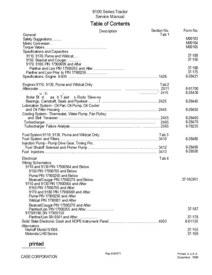
9100 Series Tractor Service Manual Table of
Contents Description
Section No. Tab 1
Form No.
General Safety Suggestions .......... Metric
Conversion .
M00103 M00104 M00105
Torque Values ....................................
............................. Specifications and
Capacities 9110, 9130, Puma and Wildcat.....
9150, Bearcat and Cougar................ 9170,
9180, PIN 17900699 and After Panther and Lion PIN
17900255 and After ...............................
. Panther and Lion Prior to PIN 17900255
......................
37-189 37-156
37-188 37-175 8-28421
Specifications, Engine 6-830 .....................
..................................................
............................ 1426
Engines 9110, 9130, Puma and Wildcat Only Aftercooler ......................................................................................... Tab 2 ..................................... 2011 8-91700
ea Et r .................... ' 2415 8-28430
l!nder BI d aa h T aist s Rods 'Sleeves Bearings,
Camshaft, Seals and Flywheel ............!
............................ .....................
........... 2425 Lubrication System - Oil Pan,
Oil Pump, Oil Cooler and Oil Filter Housing
.............................................
........................ .........................
......... 2445 Cooling System - Thermostat, Water
Pump, Fan Pulley and Belt Tensioner
..................................................
..................................................
........... 2455 Turbocharger.....................
..................................................
..................................................
... 2465 Turbocharger Failure Analysis
..................................................
................... ....... ..................
2565
8-28440
8-28450
8-28460 8-28470 9-78235
Fuel System 9110, 9130, Puma and Wildcat Only Tab
3
8-28480
Fuel System and Filters ..........................
..................................................
............................... 3410
Injection Pump - Pump Drive Gear, Timing
Pin, Fuel Shutoff Solenoid and Primer Pump
..................................................
........................... 3412 Fuel
Injectors...............................,.........
..................................................
................................. 3413
8-28490 8-28500
Electrical Tab 4
Wiring Schematics
9110 and 9130 PIN 17900564 and Below
9150 PIN 17900705 and Below
Puma PIN 17900250 and Below Bearcat/Cougar PIN 17900270 and Below 37-16OR1
9110 and 9130 PIN 17900564 and After
9150 PIN 17900705 and After
9170 and 9180 PIN 17900669 and After
Puma PIN 17900250 and After
Wildcat PIN 1790001 and After
Bearcat/Cougar PIN 17900270 and After Panther/Lion PIN 17900255 and After............................. 37-187
9170/9180 SN 17900150
Panther/Lion SN 6501 and After..................... Panther/Lion SN 6501 and After..................... 37-178
Solid State Electronic Dash and ROPS Instrument Panel..................... ................................. 4003 Solid State Electronic Dash and ROPS Instrument Panel..................... ................................. 4003 8-81130
Alternators Niehoff Model N1056 . Alternators Niehoff Model N1056 . 37-155
Motorola LHB Series Motorola LHB Series 37-169
printed
Rac 8-91571
Printed in U.S A Dcccmbcr, 1989
CASE CORPORATION
2
9100 Series Tractor Service Manual Table of
Contents Description
Section No. Tab5
bOfm NO.
Steering
Steering Column ..................................
...................
37-093 37-153 8-81100
Steering Controls Unit............................
..................................................
....................... Front Axle
Steering..........................................
..................................................
....................... 5001
Power Train Tab 6
Controlled Traction Electric Shift Unit...................................................................................... Controlled Traction Electric Shift Unit...................................................................................... M0100
K598-60/70 and K598-64/74 Axle............................................................................................ K598-60/70 and K598-64/74 Axle............................................................................................ 37-163
K598-60/70 Axle ("NOK" Seal)................................................................................................. 6002 K598-60/70 Axle ("NOK" Seal)................................................................................................. 6002 8-81090
AP3445 Axle ............................................................................................................................. AP3445 Axle ............................................................................................................................. 37-171
K592-20/30 Axle..............................................................................................,........................ 6003 K592-20/30 Axle..............................................................................................,........................ 6003 8-81120
EW-16 Powershift Transmission, Removal and Installation .................................................... EW-16 Powershift Transmission, Removal and Installation .................................................... 37-174
EW-16 PowerShift Transmission, Repair ...........................................,........,........,..........,........ EW-16 PowerShift Transmission, Repair ...........................................,........,........,..........,........ 37-168
Powershift Transmission Charge Pump .................................................................................. 6012 Powershift Transmission Charge Pump .................................................................................. 6012 8-81660
PTO Drive Unit .... . PTO Drive Unit .... . 37-170
Brakes Tab 7 Caliper Disc Brake System ........................ Brakes Tab 7 Caliper Disc Brake System ........................ 37-179
Hydraulics Tab 8 Hydraulic Specifications and Schematics .......... Hydraulics Tab 8 Hydraulic Specifications and Schematics .......... 37-166
Three Point Hitch Alignment and Valve Service ...................................................................... 8021 Three Point Hitch Alignment and Valve Service ...................................................................... 8021 8-81670
Chassis Tab 9 Tab 9
37-172
H Ui i dB
d n 9110,"9130 91'50 " " " " ' "" "
37-177 37-136 37-180
t
E,
Heating,' Ventilating, Air Conditioning 9170,
9180'Panther and'Lion..........................
......I... Air Ride Seat ........................
..................................................
..................................................
How k Works Tab 10
Printed in U S A December 1989
Rac 8-91571
3
Safety Suggestions The manufacturer, dealer
and/or agent can not anticipate every possible
circumstance that might involve potential hazard.
The Warnings, Cautions and Safety Suggestions in
this manual are therefore not all inclusive. If
an operating procedure, tool device, maintenance
or work method not specif- ically recommended is
used, you must also ensure that the product will
not be damaged or made unsafe by the procedures
you choose.
- Always weld and/or grind only in safe areas away
from any flamable or explosive materials.
- Always read the operation instructions and
understand the proper use of test equipment or
other special tooling.
- Always inspect all lift tie chains and/or slings
periodically, replace any that show signs of
damage.
Whenever you see this symbol, it means Attention!
Become Alert! Your safety is involved.
- Always use a rated alloy chain for lifting or a
sling of a size and type adequate for the
intended usage.
- Always observe and heed all caution and
warning signs or other decals wherever they may
appear.
- Always relieve all pressure in air, oil or water
systems before any lines, fittings or related
items are disconnected or removed. Be alert for
possible fluid pressure or spring force when
disconnecting or repairing any device from a
system that utilizes fluid pressure or spring
force.
- Always install the locking bar between the front
and rear frames whenever possible -
- Before service work is done near center of
tractor - Before lifting or transporting the tractor on
another vehicle - Before operating stationary PTO driven equip-
ment
- Always reinstall all fasteners with the same part
number. Do not use a lessor quality fastener if
replacements are necessary.
- Always wear eye protection a'hen charging,
boosting or performing other services to or
around batteries.
- Never perform any service or maintenance in the
center hinge area of a 4 wheel-drive articu-
lated tractor unless the engine is shut off and
the switch key removed.
- Never spin or rotate bearings with compressed
air.
- Never clean, service or adjust the tractor or any
equipment operated by it until the tractor
engine is shut down and all machine motion is
stopped, unless specific instructions are g iven
for a particular repair or procedure.
- Never attempt to lift or jack an object that
exceeds the weight capacity of the lifting
fixture (jack, hoist, fork lift etc.).
- Never wear loose fitting clothing around rotating
shafts or machinery. Long hair should always be
netted.
- Always direct compressed air away from the body
and towards a safe area. Use only an approved
air nozzle and wear adequate eye protection.
- Do not try to locate high pressure fluid leaks
with your hands. Use cardboard or wood to
search for suspected leaks. High pressure fluid
escaping from a very small area can be nearly
invisible. If injured by high pressure fluid,
seek immediate medical attention. Serious
infection or reaction can develop if proper
medical treat- ment is not administered
immediately.
- Always keep hand tools in good condition and
proper working order. Replace any that are
damaged.
- Always have electrical equipment and cords
serviced and/or inspected periodically. Use only
properly grounded electrical equipment.
- Do not use unguarded grinding tools or other
power tools requiring a guard. Wear safety
glasses and safety shoes whenever they may be
required.
- Always keep shop floors dry and clean to pre-
vent falls of people and/or equipment.
M00103
Printed in U.S.A.
4
https//www.ebooklibonline.com Hello dear
friend! Thank you very much for reading. Enter
the link into your browser. The full manual is
available for immediate download. https//www.ebo
oklibonline.com
5
- Do not attempt to separate or disassemble
hydraulic cylinders with the use of compressed
air or hydraulic pressure. - Do not attempt tire repairs unless you have the
proper equipment and know how to perform the
repair correctly and safely. - Do not work on anything that is supported only
by lift jacks or a hoist. Always use adequate
blocks or proper stands to support the product
before performing any service work. - Use only approved cleaning solvents. Never use
gasoline or other flamable or explosive
materials for cleaning. - Report or correct any unsafe areas or practices
immediately. - Before doing any electrical work, disconnect the
battery. Do not damage wiring durin g
removal operations. Reinstall the wiring so it
is not damaged nor will it be damaged in
operation by contacting sharp corners, or by
rubbing against objects or sharp corner. - If guards or shields must be removed to perform
the repair or service, use extra caution. After
the repair is completed, be sure to reinstall
any quard or shield that was removed. - These are a few of the most common causes of
personal injuries. There are a great many more
and shops are continually finding accidents
happening that they never heard of before. - The only known way to reduce personal injury, is
to teach and practice Safety First.
Printed in U.S.A.
6
GENERAL SPECIFICATIONS
AND CAPACITIES Case IH 9110 and 9130
Series P.I.N. 17900564 and After Steiger Puma
1000 Series P.I.N. 17900250 and After Steiger
Wildcat 1000 Series P.I.N. 17907001 and After
Service Manual
CASE CORPORATION
37-189 (2M, 10-87)
Issued October, 1987 Printed in U.S.A.
7
Contents Axle ....................................
............................. 1 Brakes
..................................................
............ 1 Cab ...............................
.................................. 2 Fuel System
..................................................
...... 2 Electrical .............................
.............................. 3 Transmission
..................................................
..... 3 Hydraulic System .........................
......................... 4 3-Point Hitch
..................................................
..... 4 PTO System ...............................
......................... 4 Engine
..................................................
...... ..... 5 Shipping Weight Warranted Weight
............................ 6 Speed Chart
..................................................
...... 6 Frame Dimensions ........................
......................... 7 Tire Loads
Inflation Pressures ............................
... . 8 Ballast ..........................
............... ............... 9, 10 Tread
Setting Dimensions ...............................
..... 10-13 Wheel Adjustment Procedure
................................ 13, 14 Torque
Values ..........................................
...... 15-17
Issued October, 1987 37-189
Printed in U.S.A.
8
IMPORTANT All fluid capacities list- ed
throughoutthissection area guide
to the quantities required. Always
use dipsticksor level plugstoensure
that the units are filled to the correct
level.
General Specifications Axle (Puma and
91IO) Model AP-3445 Adjustable Bar (front rear
torque proportional limited slip differential)
Type Single reduction inboard planetary, spiral
bevel ring gear and pinion Bar Diameter 4.0 in.
(10.16 cm) Axle Length 119.5 in. (303.5
cm) Wheel Spacing Adjustable from 60.0 in.
(152.4 cm) to 130.0 in. (330.2 cm)
Ratio 26.151 Oil Capacity 8.0 US gal. (30.2
L) Oil Type HD 80W-90 gear oil or other quality
oils that meet API classification GL-5 and/or
MII-L-2105B military specifications Axle (Wildcat
and 913O) Model Raba K592 Ajustable Bar Type
Single reduction inboard planetary, spiral bevel
ring gear and pinion Bar Diameter 4.0 in. (10.16
cm) Axle Length 119.5 in. (303.5 cm) Overall
Ratio 25.2941 Wheel Spacing Adjustable from
60.0 in. (152.4 cm) to 130.0 in. (330.2 cm) Oil
Capacity 11.75 US gal. (44.5 L) Oil Type HD
80W-90 gear oil or other quality oils that meet
API classification GL-5 and/or MII-L-2105B
military specifications Brakes Type Hydraulic,
self-adjusting single caliper, dual piston, disc
brake Disc Diameter 15 in. (38.1 cm) Mounting
Transmission Park Brake Integral with service
brake caliper, hand operated, cable
actuated Master Cylinder Hydraulic Fluid Type
SAE-J1703D or DOT-3 brake fluid Fluid Capacity 1
qt (0.946L) Disc Resurfacing Limits 0.015 in.
(0.38 mm) maximum per side
Figure 1 AP-3445 Axle
Figure 2 K592 Axle
1
9110, 9130, Puma/Wildcat 1000 Specifications Print
ed in U.S.A.
Issued October, 1987 37-189
9
General Specifications
ROPS Four post design certified to OSHA- 29CFR
1928 subpart C and/or ASAE S383, SAE J1194 to
44,000 lb (19,958 Kg) and CSA B352- M1980 clause
5 _at_ 44,000 lb. Mounting Rubber isolator (4)
Glass Tinted-all Access Door Left hand
damper used for opening Seat Mechanical
deluxe, fabric covered cush- ion, swiveling,
fully adjustable (air suspension
optional). Radio Optional AM/FM stereo or AM/FM
stereo cassette Steering Wheel Tilt/Telescoping
type column Climate Control Constant flow cab
pressuriza- tion, A/C and heating, aspirated cab
air intake filtration svstem Instruments
Centralized solid state electronic dash display
with function indicator lights and digitized LCD
readouts for MPH, Engine and PTO rpm and gear
selected. ROPS post gauge panel for hourmeter,
fuel level, voltmeter, engine coolant
temperature, engine and trans- mission oil
pressure. Windshield Wipers electric front
center (std)
Capacity 115 US gals. (435L), integral with rear
frame Fuel Type Grade No. 1D or Grade No. 2D
fuel as defined by ASTM designation D975 for
Diesel Fuels. Use No. 2D when ambient tempera-
tures are consistantly above 32 F (0 C).
2
Issued October, 1987 37-189
9110, 9130, Puma/Wildcat 1000 Specifications Print
ed in U.S.A.
10
General Specifications Electrical Type Parallel
12 volt, negative ground system Batteries Two
(2) 12 volt. 1250 CCA _at_ 0 F (-17.8 C) 625 CCA
per battery _at_ 0 F (-17.8 C) Alternator 105 amp
with built-in regulator Engine Block Heater 750
watt, 110 volt Ether Start Aid Optional Starter
12 volt negative ground, solenoid acti- vated
positive engagement Lighting Six (6) halogen
sealed beam lights (four front and two rear) 2
rear reflectors. Hazard flasher with integral
turn signals. Rear remote electrical receptacle,
one cab dome light. Diagnostic warning lights and
back lighting of dash readout, eyebrow lighting
of overhead console and right side control
console. Hourmeter RPM actuated (300 rpm
minimum) Tractor Monitor System Audio warning
alarm and indicator warning lights for both
critical and non-critical functions. Circuit
Breakers Automatic reset type Overhead Console
Drop down type for access to electrical
circuitry Bulb or Lamp Replacement Front
Headlamps (65W high - 35 low) No. H6054
Front Rear Flood Lamps (60W) P/N 20-1822T1
Electronic Dash Indiator Bulbs No. 194
Overhead Console Bulbs No. 53
Right Side Control Console Bulbs P/N 20-1384T1
ROPS Post Gauge Panel Bulbs No. 1893
Stop/Tail Lamp Bulb No. 1157
Cab Dome Lamp Bulb No. 1141
Hazard Flasher Lamp Bulb No. 1156
Transmission Type Powershift Model EW16 Speeds
12 forward, 2 reverse Master Clutch Wet
hydraulic type, integral with transmission.
Modulated engagement, pressure lubricated and
oil cooled. Oil Type Hydraulic/Transmission oil,
blended to JDM J20B or equivelant. DO NOT use
multi- viscosity oils. Oil Capacity 9 US gal.
(34.0L) approx
Always allow transmission fluid ample time to
warm up following engine startup before shifting
out of neutral when ambient temperatures fall to
40o F (5 C) or lower. If temperatures remain
consistently below 40 F (5 C) oil blended to
JDM J20A or equivelant is acceptable.
IMPORTANT Do not use multi-viscosity oil. Check
transmission oil level once every ten hours
of operation. Check oil level only after engine
has been stopped for at least 30 minutes and
tractor is parked on a level surface. Fill only
to full mark on the dipstick. Do not overfill.
3
9110, 9130, Puma/Wildcat 1000 Specifications Print
ed in U.S.A.
Issued October, 1987 37-189
11
General Specifications Hydraulic System Type
Closed center, load sensing, pressure
compensating Reservoir Capacity 18.0 US gals.
(68.0L). Pres- surized to 5 psi (34.45 kPa) and
225 F (105 C) warning sensor. Steering
Articulated, full priority, load sensing
hydrostatic with 2 double acting cylinders Front
Steer Axle (Optional) Type Single double acting
cylinder, operated from load sensing hydrostatic
steering con- trol valve. Provides 6 left/right
front axle turning capability. Micro-processor
controlled system. Remote Control Valve Closed
center, stack type. Remote mounted and direct
linkage actu- ated. Detented in the working
position with hydraulic kick-outs. Individual
section float positions and flow control 2 to
27 gpm (7.6 to 102.2 L/min) System Operating
Pressure 2500 psi (172.4 bar, 17,225 kPa)
maximum Pump Capacity Approx 27 gpm (102.2
L/min) _at_ 2100 rpm Filtering System Eight micron
special micro- glass element. Suction screen
inside reservoir Oil Type Hytran Plus
Hydraulic/Transmssion fluid, or 10W Antiwear
Hydraulic Fluid Couplers ISO standard, lever
type couplers and male tips
Figure 8
3-Point Hitch (Optional) Type Category III
free-link hitch - meets or exceeds SAEJ715
standards for attachment to Category III
implements. Lift capacity 24 in. (61 cm) behind
draft arm uniball - 10,000 Ibs (4540
kg) Quick-Coupler Category III, meets or
exceeds SAE-J909b standards for attach ment to
Cate- gory III implements. PTO System
(Optional) Type Live and independent system
integral with transmission. Lever actuated,
hydraul- ically operated wet clutch with integral
hydraul- ically applied brake when control is
shut-off. Shaft turns free when engine is shut
off. Speed 1000 rpm _at_2100 engine rpm Output
Shaft 1.75 in. (4.4 cm) diameter, 20 splines and
flip-up shield Lubrication Type SAE 10W 30
Capacity 1.7 US qts (1.6 L)
4
Issued October, 1987 37-189
9110, 9130, Puma/Wildcat 1000 Specifications Print
ed in U.S.A.
12
General Specifications
10
Engine Left Side
Engine Right Side
- Coolant Surge Tank
- A/C Compressor
- Fuel Injection Pump
- Ether Start
- Engine Air Cleaner
- Fuel Shutoff Solenoid
- Water Separator
- Fuel Filter
- Fuel Lift Pump
- Oil Fill
1-CooIant Heater 2-Starter 3-Oil Filter
- CooIant Filter
- Oil Drain 6-AIternator
Engine
Tractor Model Puma Wildcat
Engine Mîlke Case Case
Type I n-Line 6 In-Line 6
M0deI 6T830 6TA830
DispIaceiTlent 504.5 cu in. (8.27L) 504.5 cu in. (8.27L)
Rated H0fS90W9r 190 (141.5 Kw) 220 (163.9 Kw)
Rzted RPM (R/mÎn) 1700-2100 1700-2100
High IdIe n0 I0ad) 2310 approx 2310 approx
Low idle 850 approx 850 approx
Operating TorqUe (2100 rpm) 475 ft Ib (644 N.m) 550 ft Ib (746 N.m)
Torque Rise 30 30
B0re StFoke 4.49 x 5.32 in. (114 x 135 mm) 4.49 x 5.32 in. (114 x 135
Û0ITIF9SSI0I1 ÎÎ3IÏ0 16.51 16.51
Firing Order 1-5-3-6-2-4 1-5-3-6-2-4
Valve Settillg (C0Id) I ntake - 0.012 in. (0.30 mm) Exhaust - 0.024 in. (0.61 mm) Intake - 0.012 in. (0.30 mm) Exhaust - 0.024 in. (0.61 mm)
Oil Capacité (includes filters) 23.7 US qts (22.4L) 23.7 US qts (22.4L)
C00l8nt CapaCitÿ 35 US qts (33.1L) 35 US qts (33.1L)
Oil PressMre (mlnimum) Low idle 10 psi (69 k Pa) High idle 30 psi (207 kPa) Low idle 10 psi (69 kPa) High idle 30 psi (207 kPa)
Lubricating Oil Use multi-viscosity, preferable
15W-40 meeting API Classification CC/CD NOTE
10W-30 may be used in ambients consisiantly below
23 F (-5 C).
5
lssued October, 1987 37-189
9110, 9130, Puma/Wildcat 1000 Specifications Print
ed in U.S.A.
13
General Specifications Approximate Shipping
Weight Puma 1000 9110
Maximum Warranted Weight 24,000 lbs. (10,896 Kg)
Puma and 9110 26,000 lbs. (11,778 Kg) Wildcat and
9130
18,879 Ibs. (8,571 Kg) with 18.4 x 38 RI (6
ply) singles, PTO and steerable front axle less
fuel and operator. Add 1736 lb (788 Kg) for TPH
and Ouick Coupler.
NOTE The maximum warranted weight listed is the
maximum ballasted G VW with a 60 front and 40
rear static split.
Wildcat 1000 and 9130 25,022 lbs. (11,334 Kg)
with 18.4 x 38 RI Hub Style Duals. 21,530 lbs.
(9,775 Kg) with 18.4 x 38 RI singles. Front steer
axle, PTO and TPH with Quick Coupler, less fuel
and operator.
Speed Chart
Tire And Ground Speed Data There are many
variables to consider when deter- mining ground
speed. For example, the rolling radii of tires
are not absolute values, on some tire sizes there
could be as much as 3 variation between tire
manufacturers. The indicated values shown are
static dimensions dynamic values cannot be used
because they vary with tractor weight, weight
trans- fer, soil conditions and tire air
pressure. These variables can account for
another 3-5 variation. In addition, normal
field operations are performed with 10-15 slip.
Engine RPM 2100
Transmission Powershift
Puma and Puma and 9110
Gear MPH (KPH)
1 1.9 (3.1)
2 2.3 (3.7)
3 2.9 (4.7)
4 3.5 (5.6)
5 4.2 (6.7)
6 5.1 (8.2)
7 6.2 (9.9)
8 7.4 ( 11.9)
9 9.1 (14.6)
10 11.2 (18.0)
11 13.4 (21.5)
12 16.5 (26.5)
R1 2.5 (4.0)
R2 4.6 (7.4)
Wildcat and 9130 Wildcat and 9130 Wildcat and 9130
Gear MPH (KPH)
1 2.0 (3.3)
2 2.5 (3.9)
3 3.0 (4.9)
4 3.7 (5.9)
5 4.4 (7.1)
6 5.5 (8.8)
7 6.5 ( 10.5)
8 7.8 (12.5)
9 9.6 (15.4)
10 11.7 (18.9)
11 14.1 (22.7)
12 17.3 (27.9)
R 1 2.7 (4.3)
R2 4.8 (7.8)
With all of these variables considered, the
published ground speed chart is for reference
only. Use the chart provided with multiplier
factors for the various tire sizes and engine
speeds if more precise speed data is required.
Speeds shown represent following tire sizes at
rated rpm (2100)
NOTE Variable ground speeds are possible with
high torque rise engines within 2100 rpm and
17Ifi0 rpm.
18.4 x 38 R1 24.5 x 32 LS2
23.1 x 34 R1 20.8 x 38 R1
24.5 x 32R1 30.SL x 32 R1
To determine speed for other tire sizes use the
following chart multipliers Engine Speeds I f
MPH is wanted for engine speeds other than rated,
MPH MPH (Chart) x Engine RPM Rated
RPM Example If chart speed was 14.6 MPH and
tractor has engine with rated speed of 2100 RPM
and MPH wanted at 1800 RPM
Average Static Loaded R.R. Tire Size Factor
30.5 14.9 x 38 .96
30.5 16.9 x 38 .96
30.7 20.8 x 34 RI .96
33.5 20.8 x 38 R2 1.05
33.7 18.4 x 42 R 1 1.05
34.6 20.8 x 42 RI 1.09
33.0 30.5L x 32 R2 1 03
32.5 30.5L x 32 LS2 1.02
Example of Use If chart speed was 14.6 MPH and
tractor was equipped with 20.8 x 34 R1 tires,
Then MPH
14.6 x 1800 12.5 MPH 2100
Then MPH (Chart) x (Factor) MPH 14.6 x .96
14.0 MPH Issued October, 1987 37-189
6
9110, 9130, Puma/Wildcat 1000 Specifications Print
ed in U.S.A.
14
General Specifications
Frame Dimensions Wheel Base 120.0 in (304.8 cm)
std. frame 124.0 in. (314.9 cm) with front steer
Turning Radius (SAE) 14.0 ft (4.25 m) std.
frame 12.8 ft (3.9 m) with front steer Ground
Clearance at Drawbar 16.0 in. (40.6 cm)
Frame Articulation 40 left/right Frame
Oscillation 13 (26 total) 11 (22 total)
w/PTO Front Axle Steer (optional) 6 left/right
Specifications are subject to change without
prior notice.
7
Issued October, 1987 37-189
9110, 9130, Puma/Wildcat 1000 Specifications Print
ed in U.S.A.
15
General Specifications
Recommended Tire Loads inflation Preasures Tire
load limits at cold inflation pressure at 20 mph
(32.1 ) kph) maxim um speed
Tlre Type \ply) Slngle er Dual MiXimUItI Tire Lead _at_ rtted Inllttlsn /l0C0nImeNded PSI (kPa) (tee Nate 2) IïIaXimIJiTI PSI kPz) see 8ote 3) MaXimflnl GVW (see Nate I)
14.9 x 38 R-1 (6) D 3630 Ib _at_ 20 psi 18-16 20-18 24,000 Ibs
(1644 Kg) _at_ (138 kPa) (124)-(110) (138)-(124) (10,896 Kg)
16.9 x 38 R-1 (6) 4140Ib _at_ 18 psi 16-14 18-16 24,000 Ibs
(1875 Kg) _at_ (124 kPa) (110)-(96) (124)-(110) (10,896 Kg)
16.9 R x 38 R-1 D 4340 Ib _at_ 18 psi 16-14 18 24,000 Ibs
(1966 Kg) _at_ (124 kPa) (110)-(96) (124) (10,896 Kg)
18.4 x 34 R-1 (6) 43601b _at_ 16 psi 14-12 16-14 24,000 Ibs
(1975 Kg) _at_ (110 kPa) (96)-(83) (110)-(96) (10,896 Kg)
18.4 x 38 R-1, R-2 (6) D 4620 Ib _at_ 16 psi 14-12 16-14 24,000 Ibs
(2093 Kg) _at_ (110 kPa) (96)-(83) (110)-(96) (10,896 Kg)
18.4 x 38 R-1 (8) S 5980Ib _at_ 20 psi 20 20 21,500 lbs
(2709 Kg) _at_ (138 kPa) (138) (138) (9740 Kg)
18.4 R x 38 R-1 S 6000lb y6 18 psi 18 18 21,500Ibs
(2718 Kg) _at_ (124 kPa) (124) (124) (9740 Kg)
18.4 x 42 R-1 (10) S 7360Ib _at_ 20 psi 20 20 24,000Ibs
(3334 Kg) _at_ (138 kPa) (138) (138) (10,896 Kg)
18.4 R x 42 R-1 S 7400 lb _at_ 24 psi 24 24 24,000Ibs
(3352 Kg) _at_ (169 kPa) (169) (169) (10,896 Kg)
20.8 x 38 R-1, R-2 (8) S 6820Ib _at_ 18 psi 18 18 22,500 Ibs
(3089 Kg) _at_ (124 kPa) (124) (124) (10,192 Kg)
20.8 R x 38 R-1 S 7150Ib _at_ 18 psi 18 18 24,000Ibs
(3239 Kg) _at_ (124 kPa) (124) (124) (10,896 Kg)
20.8 x 38 R-1 (10) S (3475 Kg) _at_ (152 kPa) (138) (152) (10,896 Kg)
23.1 x 34 R-1, R-2 (8) S 7110 Ib _at_ 16 psi 16 16 24,000 Ibs
(3221 Kg) _at_ (110 kPa) (110) (110) (10,896 Kg)
24.5 x 32 R-1, R-2 (10) S 8700Ib _at_ 20 psi 16 16 24,000Ibs
(3941 Kg) _at_ (138 kPa) (110) (110) (10,896 Kg)
24.5 x 32 LS-2 (12) S 9680Ib _at_ 24 psi 16 24 24,000Ibs
(4385 Kg) _at_ (169 kPa) (110) (169) (10,896 Kg)
30.5 L x 32 R-1, R-2 (10) S 9120Ib _at_ 18 psi 16 18 24,000Ibs
(4131 Kg) _at_ (124 kPa) (110) (124) (10,896 Kg)
30.5 LR x 32 R-1 10,5001b _at_ 18 psi 16 18 24,000 Ibs
(4757 Kg) _at_ (124 kPa) (110) (124) (10,896 Kg)
30.5 L x 32 LS-2 (12) S (4707 Kg) _at_ (138 kPa) (110) (138) (10,896 Kg)
NOTE 1 The weight indicated is the maximum
ballasted tractor weight with a 60 front and 40
rear static split. Maximum CVW is also limited by
tire rating.
NOTE 2 When two numbers appear, they represent
the inflation pressures of the inside main
and outside dual tires respectively.
WARNING Use safety cage or chain, clip on chuck,
extension hose, wear eye protection and stand
away from the tire while inflating to prevent the
possibility of personal injury due to blowoffs,
etc.
NOTE 3 Tractor drive tires used in severe
service, it is permissable to increase inflation
pressure up to 4 psi (28 kPa) aiove that shown
in the Maximum PSI table with no increase in
tire load.
8
9110, 9130, Puma/Wildcat 1000 Specifications Print
ed in U.S.A.
Issued October, 1987 37-189
16
General Specifications
Ballast Weight Information Rather than
weighting the tractor down to pull heavy loads,
try reducing the load. Pulling a lighter load at
higher speed is cheaper and more efficient.
be times when it is desirable to weight the
tractor to decrease slippage and increase balance
or stability. Use no more ballast than necessary,
and remove ballast when it is no longer needed.
Liquid ballast should never be added until a
deter- mination is made for the need, however,
there may Liquid Weighting Valve Level (75)
Table The following table provides data on the
filling of front and rear tractor tires with
calcium chloride solution, based on 75 fill or
approximately valve level. The table is based on
the use of Type 1 (77) commercial calcium
chloride flake. If Type 2 (940/)calcium chloride
flake is used, reduce the "Lbs. CaCI2" weights in
the table by 25.
Water Only Water Only 3-1/2 lbs. CaCI 3-1/2 lbs. CaCI 3-1/2 lbs. CaCI
Tire Size Gallons WI. Lbs. Gal. H0 Lbs CaCIz Total WI. Gal. H20 Lbs. CaCI Total Wt.
14.9-38 67 559 57 200 675 54 270 720
16.9-38 90 751 77 270 912 73 365 974
18.4-34 100 834 85 298 1007 81 405 1081
18.4-38 110 917 94 329 1113 89 445 1187
18.4-42 115 959 98 343 1160 93 465 1240
20.8-38 140 1168 120 420 1420 114 570 1521
20.8-42 148 1234 127 444 1503 120 600 1600
23.1-34 159 1326 136 476 1610 128 640 1708
24.5-32 170 1418 146 51 i 1729 138 690 1841
30.5L-32 217 1809 186 651 2202 176 880 2347
To extend tire life and avoid excessive wear of
drive train components, avoid continuous full
load opera- tions at ground speeds below 3.5 mph
(5.6 km/h).
traction or stability, this ratio should be
maintained in all drawbar applications. When dual
wheels are used do not add liquid ballast to the
outside dual tires.
NOTE I f 3-Pt hitch or PTO equipped, it may not
be possible to achieve a 60-40 static
split. Desirable wheel slippage should be 10-15
percent in average conditions. This slippage rate
is important in order to gain the optimum tire
and power train life.
If liquid ballast is required, ballast to 60-40
percent, which will result in approximately 50
percent weight distribution under load. For
example if 4000 lbs of weight is to be added,
the 60-40 percent static weight ratio must be
maintained. Do not exceed the maximum warranted
vehicle gross weight for Agri- culture or
continuous duty drawbar usage.
6O
There are many factors that affect traction
and balance that need to be considered before
adding liquid ballast such as soil conditions
and/or topo- graphy, draft load of the implement
or equipment being used etc.
When using liquid ballast, use a solution of
water and calcium chloride to prevent water from
freezing. Where freezing temperatures never
occur, plain water can be used, but the weight
added will be 20 less than calcium chloride
solution.
Desirable tractor static weight distribution is
approxi- mately 40 percent of the weight on the
rear axle and 60 percent of the weight on the
front axle. If it becomes necessary to add liquid
ballast for better
Where anti-freeze protection is needed, use 3-1/2
lbs of commercial calcium chloride flake per
gallon
9
9110, 9130, Puma/Wildcat 1000 Specifications Print
ed in U.S.A.
Issued October, 1987 37-189
17
General Specifications of water, which is
completely safe to 12 below zero. For protection
to 52 below 0 use 5 lbs. of calcium chloride
flake per gallon of water.
Rear Ballast
When using front mounted utility blades or other
attachments it will usually be required to add
liquid ballast to the rear tires only to provide
stability and balance. Fill the rear inside tires
to the level required to achieve approximately 50
percent of the total static weight on each axle.
Utility blades and other mounted equipment must
be considered as ballast. Because of this, to
main- tain stability and balance, specific
ballast instruc- tions must be followed. Liquid
ballast should always be removed when not
required, if liquid ballast is required, it must
always be used in the proper ratio for the
intended application.
Combined static weight of front attachment and
rear ballast must not exceed the maximum vehicle
gross warranted weight.
Front Ballast
When fully or semi-mounted rear attachments are
used it may be desirable to add liquid ballast to
the front tires to maintain stability and
balance. Do not add ballast to the rear tires
when using fully or semi- mounted rear
attachments.
Front Mount Attachments
SPECIAL NOTE Total maximum allowable weight is
2500 lbs (1135 Kg) for front frame mounted liquid
tanks. Weighting beyond 2500 lbs (1135 Kg)
requires additional front frame structure. Remove
all ballast from he front axle tires.
Fill the front inside tires to the required level
to provide stability and balance.
Combined static weight of the tractor and front
ballast must not exceed maximum vehicle gross
warranted weight.
Tread Setting Dimensions Dual combinations using
Steiger wheel equipment will provide spacing for
30 inch and 32 inch rows. However, if 18.4 x 42
R-1 or 20.8 x 38 R-1 tires are used some tread
settings will require the use of steering
cylinder stops and oscillation stop adjust- ment
to prevent cab/tire interference and/or front to
rear tire interference in a full turn and/or
oscillation mode. IMPORTANT If other after
market wheel equipment is used, you must always
check for cab/tire interfer- ence in a full turn
and/or oscillation mode. Figure 12 Articulation
Cylinder Stop
9110, 9130, Puma/Wildcat 1000 Specifications Print
ed in U.S.A.
Issued October, 1987 37-189
10
18
General Specifications Tread Setting
Dimensions Steering cylinder stops are furnished
with the tractor only if the tractor is shipped
from the factory with wheel equipment requiring
stops. Contact your dealer if articulation or
oscillation stops are needed. (Each set of stops
measure 0.75 in. (19 mm) in length. Some tread
settings may require one set of stops per
cylinder while other settings may require two
sets of stops per cylinder.)
Figure 13 Articulation Cylinder Stops
In addition to the steering cylinder stops, the
oscilla- tion stop bolt may require the
installation of one or more 0.25 in. (6.35 mm)
thick washers in addition to the one washer
installed as standard. Reference the
Articulation and Oscillation Stop Setting Chart
for steering cylinder stop requirements and
oscillation stop washer requirements. If chart
shows standard (std) in the respective
osciIIaton or steering cylinder stop column, no
stop adjustment is required.
Articulation and Oscillation Stop Settings For
Steiger Wheel Equipment
Treed width 14.9 x 38 16.9 x 38 18.4 x 34 8.4 x 38 R-1 18.4 x 38 R -2 ouale 30 Inch 32 Inch Std Std Std Std Std Std Std Std Std Std Std Std Std Std Std Std Std Std Std Std Singles ouale 30 Inch 32 Inch Std Std Std Std Std Std Std Std Std Std Std Std Std Std Std Std Std Std Std Std Singles ouale 30 Inch 32 Inch Std Std Std Std Std Std Std Std Std Std Std Std Std Std Std Std Std Std Std Std Singles ouale 30 Inch 32 Inch Std Std Std Std Std Std Std Std Std Std Std Std Std Std Std Std Std Std Std Std Singles
18.4 x 38 R-1, R-2 Std Std Std Std
i . 25 in (5) 4 50 in. i .25 in. (5) 4.50 in.
20.8 x 38 R-1 i . 25 in. (S) i .50 in i .25 in (5) y.50 in.
20.8 x 38 R-2 1.50 in. (6) 1.50 in. 1.50 in. (6) 1.50 in.
23.1 x 34 R -1. R-2 See Note 3 See Note 3 See Note 3 See Note 3
24.5 x 32 See Note 3 See Note 3 See Note 3 See Note 3
30.5 x 32 See Note 3 See Note 3 See Note 3 See Note 3
IMPORTANT NOTICE When 18.4 x 38 or 18.4 x 42
fires are used at a 60 inch tread setting on
models equipped with an optional front steer
axle, tire wall to cab mount clearance is
normally close. To avoid tire damage due to
production tolerances, if 18.4 x 38 or 18.4 x 42
tires are used at a 60 inch tread setting, tire
call to cab mount interference must always be
checked in both directions.
There should be a minimum of one-fourth (1f4)
inch clearance between the tire wall and front
cab mount in both directions of steering. Adust
the wheel hub on the axle slightly if necessary
to assure the minimum clearance requirements.
NOTE 1 Dimension s tated is length of steering
cylinder stops required.
20.8 x 38 tires cannot be used at a 60 inch tread
setting on models equipped with a front steer
axle.
NOTE 2 Number in ( ) denotes total number of .25
in. washers required.
NOTE 3 I f these size tires are used as singles,
in tread widths of 118 in. or greater, always
check for cab/tire and/or Iront to rear fire
interference, aojos/ ocillation stops andf or add
steering cylinder stops as required to o6tain
clearance. SPECIAL NOTE I f PTO is installed,
1.50 in. of oscillation slop adjustment is
required.
11
Issued October, 1987 37-189
9110, 9130, Puma/Wildcat 1000 Specifications Print
ed in U.S.A.
19
General Specifications Tread Setting
Dimensions NOTE Minim um tread width B for
sing/es is 60 in. (152.4 cm) maximum tread width
C or E for singles or duals and all wheel
combinations is limited to 130 in. (330.2 cm).
Wheel Spacing Tread Setting Dimensions
Tire Size s0e N0t0(J) A B D D D D
Tire Size s0e N0t0(J) Nin Nin (Igax Nax Disc In Nin (MaX) Disc In Nin (MaX) Disc Out Nin IYIaX) Disc Out Nin IYIaX) Disc In Min NaX Disc In Min NaX Disc Out Nin (NOX) Disc Out Nin (NOX)
14.9 x 38 45 60 (71) 75 119 (130) 109 (120) 134 (145) 124 (135)
16.9 x 38 43 60 (71) 77 119 (130) 109 (120) 136 (147) 126 (137)
18.4 x 34 42 60 (71) 117 119 (130) 109 (120) 137 (148) 127 (138)
18.4 x 38 (1) 42 60 (71) 117 119 (130) 109 (120) 137 (148) 127 (138)
18.4 x 42 42 60 (119) 137 N/A N/A N/A N/A N/A N/A N/A N/A
Disc out
18.4 x 42 54 72 (130) 148 N/A N/A N/A N/A N/A N/A N/A N/A
Disc in
20.8 x 38 Disc out 20.8 x 38 Disc in 39 51 60 (119) 72 (130) 140 151 Note 2 N/A N/A N/A N/A N/A N/A N/A N/A N/A N/A N/A N/A N/A N/A N/A N/A
23.1 x 34 Disc out 23.1 x 34 Disc in 41 46 64 (122) 69 (127) 145 Note 2 150 Note 2 N/A N/A N/A N/A N/A N/A N/A N/A N/A N/A N/A N/A N/A N/A N/A N/A
24.5 x 32 Disc out 24.5 x 32 Disc in 40 44 64 (123) 68 (126) 147 Note 2 150 Note 2 N/A N/A N/A N/A N/A N/A N/A N/A N/A N/A N/A N/A N/A N/A N/A N/A
30.5 32 Disc out 30.5 x 32 Disc in 39 39 70 (119) 70 (130) 150 Note 2 161 Note 2 N/A N/A N/A N/A N/A N/A N/A N/A N/A N/A N/A N/A N/A N/A N/A N/A
Letters refer to Wheel Spacing Chart. All
dimensions are stated in inchs. N/A denotes
not approved In dual configuration. NOTE 1 Max
single dimension is same as file max dual
dimension. NOTE 2 Refer to steering cylinder
and oscillation stop chart. Check
forneedofsteering cylinderstops and/oroscilIation
stop adjustment. Refer to the following page for
Disc In or Disc Out information.
9110, 9130, Puma/Wildcat 1000 Specifications Print
ed in U.S.A.
Issued October, 1987 37-189
12
20
General Specifications Tread Setting
Dimenaiona Inner wheel hub locking bolts must
face to the outside. With dual tires, space A
between bias-ply tires must be at least 4 in.
(100 mm). More space may be needed between radial
ply tires.
Outer Wheel Disc In igure 15 Inner W'fiee/ Hot
Bo/is fo Outside
Outer Wheel Disc Out Figure 16 Inner Wheel Hub
8o/rs to Outside
- Wheel Adjustment Procedure
- Park the tractor on a level surface, apply the
park brake. Lift and support the tractor only
hig h enough to allow the tire to clear so that
the wheel assembly will slide on the axle
shaft. - Loosen and remove the four hub lock ing cap-
screws and washers (Item 1 ). Replace these
capscrews with the four special jack screws
suppl ied with the tractor.
Figure 18 Jack Screws
9110, 9130, Puma/Wildcat 1000 Specifications Print
ed in U.S.A.
Issued October, 1987 37-189
13
21
General Specifications
- Loosen and back the oth er two remaining cap-
screws (3) out th ree complete turns (approx.
1/4 in. 63.5 mm). - Tig hten th e four special jack screws (2) on eac
h bushing half alternately and evenIy to
break loose the tapered bus hing halves from the
wheel hub and axle.
5. Adjust the wheel(s) to the desired work
ing position at on g the bar axle. Reference the
wheel spacing chart for correct dimensions
relative to tire size and disc "in" or "out"
placement. Normally all wheels shoul d be the
same distance from the tractor center line.
Reference the Tread Setting Chart .
Figure 19
- If the desired dual wheel tread setting cannot be
obtained because of outer wheel disc position,
the outer wheel disc position cannot be changed
on the same side of tractor. To change wheel rim
disc position and maintain proper direction of
tire rotation, move each tire to the opposide
side of the tractor. - After the wheel hub is positioned on the bar,
remove the four special jacking screws and
replace them with the original capscrews and
washers removed in step No. 2. - Next tig hten the th ree (3) capscrews on the
bushing half assem bly (A), with the key and
dowel pins, alternately and evenly to 280 14 Ib
ft (379 N.m). The face of this bushing half
must contact the face of the hub. - Repeat the same procedure described above to tig
hten the capscrews on the remaining bushing half
(B) without the dowel. The face of this bushing
must not contact the face of the hub. - IMPORTANT Follow the above described procedure
for each wheel requiring removal or adjustment. - After the wheel spacing setting is completed,
and before placing the tractor under load, run
the tractor a short distance (approx. 200 yards - 183 m ) and recheck each bushing capscrew for
the specified torque. - IMPORTANT On new tractors, check the hub
bushing capscrews to the speci(ied torque after
the first 3 hours oi operation and every 10 hours
of operation thereafter until the capscrews
remain tight. This must be done any time the
wheel hubs have been loosened for any reason. Be
sura axlo har end snap ring Is In piace after
wheel removal or
'heel
other work to rezfzzce the possibility ol the
sliding all II loosened. Issued October,
1987 37-189
14
9110, 9130, Puma/Wildcat 1000 Specifications Print
ed in U.S.A.
22
General Specifications Special Torque Values
Cab Mount Attaching Bolts Torque all cab mount
attaching bolts to 564 34 ft lb (765 1 46
N.m). CAUTION If the ROPS cab must ever be
removed or replaced, make certain that the proper
hardware is used and that the proper torque
values are applied to the attaching
bolts. WARNING The protection offered by the
ROPS cab will be impaired if it is subjected to
any modification, struc- tural damage, or has
been involved In an overturn. The ROPS cab must
be replaced after a roll over. Wheel Bolt
Torque Tighten the wheel lug bolts to 600 lb ft
(814 N.m) every 10 hours for the first 50 hours.
Repeat when- ever the wheels are removed and
remounted. IMPORTANT The 600 lb ft (814 N.m)
specification will apply when lug bolts are clean
and dry. I f lug bolts are clean and dipped in
SAE 30 oil, tighten the bolts to 450 lb ft (610
N.m).
Dual Bolt Torque (Spacer Band Style) T ighten
the dual bolts on spacer band style wheels to 200
Ib ft (271 N.m) every 10 hours for the first 50
hours. Repeat whenever the wheels are removed and
remounted. Tighten the dual bolts evenIy until
the spacer is seated. Then tig hten alternately
and evenIy in a star configuration to 200 Ib ft
(271 N.m). Do not over tighten.
Figure 24
9110, 9130, Puma/Wildcat 1000 Specifications Print
ed in U.S.A.
Issued October, 1987 37-189
15
23
General Speeifications
Acijustable Wheel Bushing Capscrew
Torque Tighten the bushing half capscrews to 280
ft lb (379 N.m) after the first 3 hours of
operation and every 10 hours of operation
thereafter until the capscrews remain tight. This
must be done any time the hub bushings have been
loosened for any reason. NOTE See Axle Wheel
Adjustment Procedure for additional information.
I/I/henever the wheel hubs are removed, all the
contact surfaces of the wheel bushings should be
greased before installation. Use multi-purpose
gun grease.
Axle To Frame Bolt Torque The front and rear
axle mounting bolts - tighten to 695 ft lb (942
N.m).
Lower Vertical Hinge Pin Lower vertical hinge
pin - tighten 1200 ft lb (1627 N.m)
Figure 27
Issued October, 1987 37-189
16
9110, 9130, Puma/Wildcat 1000 Specifications Print
ed in U.S.A.
24
Suggest If the above button click is invalid.
Please download this document first, and then
click the above link to download the complete
manual. Thank you so much for reading
25
General Specifications
Drawbar clevis Bolt Torque The drawbar clevis
bolt must be tightened to 600 ft Ib (814 N.m)
whenever the clevis is rotated from top to bottom.
Figure 28
3-Point Hitch (Option) Rockershaft pillow block
bolts - tighten to 460 ft lb (624 N.m).
Front Steerable Axle Bolt Torque The optional
front steerable axle structure must have bolts
"A" and "B" checked and tightened to the
specified torque at the first 50 and 100 hours of
operation . Tighten bolts "A" and "B" to 255
12 ft Ib (346 16 N.m)
Figure 30
17
9110, 9130, Puma/Wildcat 1000 Specifications Print
ed in U.S.A.
Issued October, 1987 37-189
26
https//www.ebooklibonline.com Hello dear
friend! Thank you very much for reading. Enter
the link into your browser. The full manual is
available for immediate download. https//www.ebo
oklibonline.com
Recommended
