

2017 Yamaha YZ250FX YZ250FXH Service Repair Manual Instant Download (Part No. B29-28199-82) PowerPoint PPT Presentation
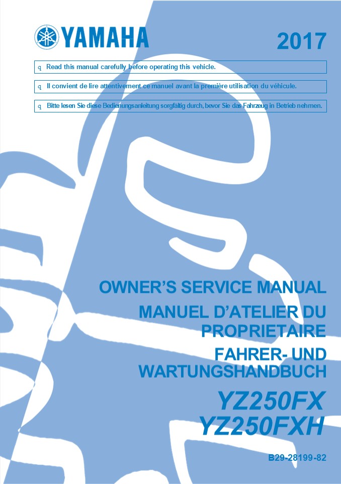
Title: 2017 Yamaha YZ250FX YZ250FXH Service Repair Manual Instant Download (Part No. B29-28199-82)
1
2017
q Read this manual carefully before operating
this vehicle.
q Il convient de lire attentivement ce manuel
avant la première utilisation du véhicule.
q Bitte lesen Sie diese Bedienungsanleitung
sorgfältig durch, bevor Sie das Fahrzeug in
Betrieb nehmen.
OWNERS SERVICE MANUAL MANUEL DATELIER
DU PROPRIETAIRE FAHRER- UND WARTUNGSHANDBUCH YZ250
FX YZ250FXH B29-28199-82
2
2017
Read this manual carefully before operating this
vehicle.
OWNERS SERVICE MANUAL YZ250FX YZ250FXH B29-28199-
82-E0
3
TABLE OF CONTENS
1
GENERAL INFORMATION
2
SPECIFICATIONS
PERIODIC CHECKS AND ADJUSTMENTS
3
4
CHASSIS
5
ENGINE
6
COOLING SYSTEM
7
FUEL SYSTEM
8
ELECTRICAL SYSTEM
9
TROUBLESHOOTING
10
TUNING
4
https//www.ebooklibonline.com Hello dear
friend! Thank you very much for reading. Enter
the link into your browser. The full manual is
available for immediate download. https//www.ebo
oklibonline.com
5
GENERAL INFORMATION LOCATION OF IMPORTANT
LABELS............................................
................1-1
1
DESCRIPTION.......................................
..................................................
.........1-4
IDENTIFICATION ...................................
..................................................
........1-5 VEHICLE IDENTIFICATION NUMBER
..................................................
....1-5 ENGINE SERIAL NUMBER .....................
..................................................
1-5 INCLUDED PARTS ..............................
..................................................
..........1-6 SPARK PLUG WRENCH
..................................................
.........................1-6 NIPPLE
WRENCH............................................
..........................................1-6 HAND
LEBAR PROTECTOR ..................................
....................................1-6 FUEL HOSE
JOINT COVER ......................................
................................1-6 COUPLER FOR
CONNECTING OPTIONAL PART..........................
.........1-6 IMPORTANT INFORMATION
..................................................
........................1-7 PREPARATION FOR
REMOVAL AND DISASSEMBLY...........................
.1-7 REPLACEMENT PARTS............................
................................................1-
7 GASKETS, OIL SEALS AND O-RINGS
..................................................
...1-8 LOCK WASHERS/PLATES AND COTTER PINS
......................................1-8
BEARINGS AND OIL SEALS ...........................
..........................................1-8
CIRCLIPS .........................................
..................................................
........1-8 BASIC SERVICE INFORMATION............
..................................................
......1-9 ELECTRICAL SYSTEM.......................
..................................................
.....1-9 SPECIAL TOOLS ..........................
..................................................
............... 1-13 CONTROL FUNCTIONS
..................................................
.............................. 1-19 WARNING
LIGHTS ...........................................
.......................................
1-19 ENGINE STOP SWITCH...........................
...............................................1-1
9 START SWITCH....................................
..................................................
.1-19 CLUTCH LEVER ...............................
..................................................
.....1-19 SHIFT PEDAL ............................
..................................................
............ 1-20 THROTTLE GRIP...................
..................................................
................1-20 FRONT BRAKE LEVER
..................................................
.........................1-20 REAR BRAKE
PEDAL.............................................
................................. 1-20 SIDESTAND
..................................................
........................................... 1-20
STARTER KNOB/IDLE ADJUSTING SCREW.................
........................ 1-20 FUEL TANK CAP
..................................................
...................................1-21
6
STARTING AND BREAK-IN ............................
..............................................1-22
FUEL ............................................
..................................................
.......... 1-22 HANDLING NOTE ....................
..................................................
..............1-22 AIR FILTER MAINTENANCE
..................................................
................. 1-22 STARTING A COLD ENGINE
..................................................
................1-22 STARTING A WARM
ENGINE............................................
.....................1-23 BREAK-IN PROCEDURES
..................................................
.................... 1-23 MAINTENANCE AFTER
BREAK-IN .........................................
..................... 1-24 MAJOR
MAINTENANCE.......................................
...................................1-24 TORQUE-CH
ECK POINTS .......................................
.....................................1-25 MOTORCY
CLE CARE AND STORAGE..............................
..........................1-27 CARE...............
..................................................
.......................................
1-27 STORAGE .....................................
..................................................
.........1-28
7
LOCATION OF IMPORTANT LABELS LOCATION OF
IMPORTANT LABELS Please read the following
important labels carefully before operating this
vehicle. 1,2,3 4,5,6 7,8 9,10,11
13 12
CAN
8
LOCATION OF IMPORTANT LABELS
EUR
9
LOCATION OF IMPORTANT LABELS
AUS, NZL, ZAF
10
DESCRIPTION
DESCRIPTION
2,3 4
1
9
8 7 6 5
10
11
14
13 12
19 18 17 16 15
1. Clutch lever
11. Radiator
2. Engine trouble warning light 12. Coolant drain bolt
3. Fuel level warning light 13. Rear brake pedal
4. Front brake lever 14. Air filter
5. Throttle grip 15. Drive chain
6. Start switch 16. Shift pedal
7. Radiator cap 17. Oil level check window
8. Fuel tank cap 18. Starter knob/idle screw
9. Engine stop switch 19. Front fork
10. Fuel tank
TIP Designs and specifications of the vehicle
are subject to change without notice. Therefore,
please note that the descriptions in this manual
may be different from those for the vehicle you
have pur- chased.
11
IDENTIFICATION
- IDENTIFICATION
- There are two significant reasons for knowing the
serial number of your vehicle - When ordering parts, you can give the num-
- ber to your Yamaha dealer for positive iden-
tification of the model you own. - If your vehicle is stolen, the authorities will
- need the number to search for and identify your
vehicle. - VEHICLE IDENTIFICATION NUMBER
- The vehicle identification number 1 is stamped
into the right side of the frame.
1
ENGINE SERIAL NUMBER The engine serial number 1
is stamped into the elevated part of the
right-side of the engine.
1
12
INCLUDED PARTS
INCLUDED PARTS SPARK PLUG WRENCH The spark plug
wrench 1 is used to remove or install the spark
plug.
FUEL HOSE JOINT COVER The fuel hose joint covers
1 are used to pre- vent mud, dust, and other
foreign materials from entering the inside when
the fuel hose is disconnected.
1
1
1
NIPPLE WRENCH The nipple wrench 1 is used to
tighten the spoke.
COUPLER FOR CONNECTING OPTIONAL PART The coupler
1 is used for connecting the op- tional Power
Tuner and so on.
NOTICE
When no optional parts, etc. are connected,
connect the connection terminal to the orig- inal
coupler. Before disconnecting the coupler, thor-
oughly wipe off any mud or water stuck to it.
HANDLEBAR PROTECTOR Install the handlebar
protector 1 with the mark a facing forward. A
1
a
Part name Part number
GYTR Power Tuner (For USA) 33D-H59C0-V2
YZ Power Tuner (Except for USA) 33D-859C0-11
1 A
The Power Tuner is an optional part.
13
IMPORTANT INFORMATION IMPORTANT
INFORMATION PREPARATION FOR REMOVAL AND DIS-
ASSEMBLY 1. Before the jobs, completely remove
mud, dust, and the like in order to prevent the
en- try of them into the inside during the jobs.
- During disassembly, clean each of the parts, and
store them in trays for each section. - Flammable. Keep servicing areas away
- from any source of fire.
- During servicing, take special care not to re-
ceive an injury or a burn on the engine, the
exhaust pipe, the silencer, or the like. - If coolant is left adhered to the chassis, paint
and plating will be damaged. Therefore, rinse
it out with water in good time.
- Before cleaning with high-pressure water of
washers, cover the following parts. - Air duct
- Silencer exhaust port
- Drain hole on the cylinder head (right side) Hole
under the water pump housing
WARNING
- Coolant is potentially harmful and should be
handled with special care. - If it enters your eyes, wash it away with wa-
- ter enough and then get medical attention
- If it splashes on your skin or clothes, quickly
wash it away with water and then with soapy
water. - If it is swallowed, immediately induce vom-
iting and get medical attention.
REPLACEMENT PARTS Make sure that the parts and
grease or oil to be used for repair of the
vehicle, including periodic replacement parts,
are new YAMAHA genuine parts and recommended
parts. Do not use any used parts, because these
may not be genuine though they have similar ap-
pearances or because the quality may be changed
by aging.
2. Use proper special tools and equipment. See
SPECIAL TOOLS.
3. During disassembly, check and measure the
required parts, and make a record of them so that
you may refer to the record when in- stalling
them. Moreover, arrange gears, cyl- inders,
pistons, and other parts for each section so as
not to confuse or lose them.
14
- IMPORTANT INFORMATION
- GASKETS, OIL SEALS AND O-RINGS
- When overhauling the engine, replace all gaskets
and O-rings. All gasket surfaces, oil seal lips,
and O-rings must be cleaned so that there may be
no dust on them. - During assembly, always apply proper oil to
bearings and proper grease to oil seal lips
before installation.
- Oil
- Lip
- Spring
- Grease
- LOCK WASHERS/PLATES AND COTTER PINS
- After removal, replace lock washers/plates 1
- and cotter pins with new ones. After the bolt or
nut has been tightened to specification, firmly
bend the lock tabs along a flat of the bolt or
nut.
CIRCLIPS When assembling parts, always use new
cir- clips. During installation of a circlip,
make sure that the edge 2 of the circlip 1 is
positioned opposite to the force 3 that the
circlip re- ceives. Install the circlip with its
end aligned with the center of the spline,
without opening the circlip more than necessary.
BEARINGS AND OIL SEALS Install bearings 1 and
oil seals 2 with their manufacturers marks or
size symbols facing outward. During installation
of an oil seal, make sure that its main lip faces
the oil chamber (the target to be sealed). Before
installation, always apply a light coat of grease
to the oil seal lip.
NOTICE
Do not spin the bearing with compressed air
because this will damage the bearing sur- faces.
15
BASIC SERVICE INFORMATION BASIC SERVICE
INFORMATION ELECTRICAL SYSTEM Electrical parts
handling
NOTICE
Never disconnect a battery lead while the engine
is running otherwise, the electrical components
could be damaged.
NOTICE
Be sure to connect the battery leads to the
correct battery terminals. Reversing the battery
lead connections could damage the electrical
components.
NOTICE
When disconnecting the battery leads from the
battery, be sure to disconnect the nega- tive
battery lead first, then the positive bat- tery
lead. If the positive battery lead is
disconnected first and a tool or similar item
contacts the vehicle, a spark could be gen-
erated, which is extremely dangerous.
NOTICE
When connecting the battery leads to the battery,
be sure to connect the positive bat- tery lead
first, then the negative battery lead. If the
negative battery lead is connect- ed first and a
tool or similar item contacts the vehicle while
the positive battery lead is being connected, a
spark could be generat- ed, which is extremely
dangerous.
TIP If a battery lead is difficult to
disconnect due to rust on the battery terminal,
remove the rust us- ing hot water.
NOTICE
Make sure that the engine is stopped after
pushing and holding the engine stop switch before
disconnecting or connecting any electrical
components.
16
BASIC SERVICE INFORMATION
NOTICE
Checking the electrical system TIP Before
checking the electrical system, make sure that
the battery voltage is at least 12 V.
Handle electrical components with special care,
and do not subject them to strong shocks.
NOTICE
NOTICE
Electrical components are very sensitive to and
can be damaged by static electricity. Therefore,
never touch the terminals and be sure to keep the
contacts clean.
Never insert the tester probes into the cou- pler
terminal slots. Always insert the probes from the
opposite end a of the coupler, taking care not
to loosen or damage the leads.
a
TIP Push and hold the engine stop switch to
turn off the engine when resetting the ECU
(Electronic Control Unit). Disconnect the starter
motor lead of the starter relay, and then push
the starter switch. Be sure to wait for five
seconds or lon- ger before pushing the start
switch after the en- gine is stopped.
NOTICE
For waterproof couplers, never insert the tester
probes directly into the coupler. When performing
any checks using a water- proof coupler, use the
specified test har- ness or a suitable
commercially available test harness.
17
- BASIC SERVICE INFORMATION
- Check
- Lead
- Coupler
- Connector
- Moisture ? Dry with compressed air. Rust/stains ?
Connect and disconnect sev- eral times.
- Checking the connections
- Check the leads, couplers, and connectors for
stains, rust, moisture, etc. - Disconnect
- Lead
- Coupler
- Connector
- Check
- All connections
- Loose connection ? Connect properly.
- TIP
- If the pin 1 on the terminal is flattened, bend
it up. - After disassembling or assembling a coupler,
- pull on the leads to make sure that they are in-
stalled securely.
NOTICE
- When disconnecting a coupler, release the
coupler lock, hold both sections of the
coupler, and then disconnect the coupler. - There are many types of coupler locks
therefore, be sure to check the type of cou- - pler lock before disconnecting the cou-
- pler.
1
NOTICE
When disconnecting a connector, do not pull the
leads. Hold both sections of the connector, and
then disconnect the con- nector.
18
- BASIC SERVICE INFORMATION
- Connect
- Lead
- Coupler
- Connector
- TIP
- When connecting a coupler or connector, make
sure that both terminals are connected securely. - Make sure all connections are tight.
- Check
- No continuity
Pocket tester 90890-03112 Analog pocket tester
YU-03112-C YU-03112-C
- TIP
- If there is no continuity, clean the terminals.
- When checking the wire harness, perform steps
(1) to (4). - As a quick remedy, use a contact revitalizer
available at most part stores.
19
- SPECIAL TOOLS
- SPECIAL TOOLS
- The following special tools are required for
accurate and complete adjustment and assembly.
Using the correct special tool will help prevent
damage caused by the use of improper tools or
improvised techniques. The shape and tool number
used for the special tool differ by country, so
two types are provided. Refer to the list
provided to avoid errors when placing an order. - TIP
- For U.S.A. and Canada, use tool number starting
with YM-, YU-, or ACC-. - For others, use tool number starting with
90890-.
Tool name/Part number How to use Illustration
Dial gauge stand set This tool is used to check
90890-01252 parts for runout or bend.
Dial gauge set
YU-03097-B
Crankshaft installer pot This tool is used to install the
90890-01274 crankshaft.
Installing pot
YU-90058
Crankshaft installer bolt This tool is used to install the
90890-01275 crankshaft.
Bolt
YU-90060
Adapter (M12) This tool is used to install the
90890-01278 crankshaft.
Adapter 3
YU-90063
Piston pin puller set This tool is used to remove
90890-01304 the piston pin.
Piston pin puller
YU-01304
20
SPECIAL TOOLS
Tool name/Part number How to use Illustration
Radiator cap tester This tool is used to check the
90890-01325 radiator and the radiator cap.
Mityvac cooling system tester
kit
YU-24460-A
Radiator cap tester adapter This tool is used to check the
90890-01352 radiator and the radiator cap.
Pressure tester adapter
YU-33984
Steering nut wrench This tool is used to remove or
90890-01403 tighten the steering nut.
Exhaust flange nut wrench
YU-A9472
Cap bolt wrench This tool is used to remove or
90890-01500 tighten the base valve.
Cap bolt wrench
YM-01500
Cap bolt ring wrench This tool is used to loosen or
90890-01501 tighten the damper assem-
Cap bolt ring wrench YM-01501 bly.
Fork seal driver This tool is used to install the
90890-01502 oil seal of the front fork.
Fork seal driver (48)
YM-A0948
Spoke nipple wrench (67) This tool is used to tighten the
90890-01521 spoke.
Spoke nipple wrench (67)
YM-01521
21
SPECIAL TOOLS
Tool name/Part number How to use Illustration
Pocket tester This tool is used to measure
90890-03112 the voltage, current, and re-
Analog pocket tester sistance of electrical compo-
YU-03112-C nents.
Timing light This tool is used to measure
90890-03141 the ignition timing.
Timing light
YU-03141
Pressure gauge This tool is used to measure
90890-03153 the fuel pressure.
Pressure gauge
YU-03153
Fuel pressure adapter This tool is used to mount the
90890-03186 pressure gauge.
Fuel pressure adapter
YM-03186
Test harness S pressure This tool is used to check the
sensor (3P) throttle position sensor input
90890-03207 voltage.
Test harness S pressure
sensor (3P)
YU-03207
Test harness lean angle This tool is used to check the
sensor (6P) lean angle sensor output volt-
90890-03209 age.
Test harness lean angle
sensor (6P)
YU-03209
FI diagnostic tool sublead This tool is used to connect
90890-03212 the Yamaha diagnostic tool
FI diagnostic tool sublead YU-03212 to a battery.
Yamaha diagnostic tool This tool is used to check er-
90890-03231 ror codes or carry out self-di-
Yamaha diagnostic tool (US) 90890-03234 agnosis.
22
SPECIAL TOOLS
Tool name/Part number How to use Illustration
Valve spring compressor 90890-04019 Valve spring compressor YM-04019 This tool is used to discon- nect or connect the valve and the valve spring. YM-04019
Spacer (crankshaft installer) 90890-04081 Pot spacer YM-91044 This tool is used to install the crankshaft. YM-91044
Universal clutch holder 90890-04086 Universal clutch holder YM-91042 This tool is used to hold the clutch when removing or in- stalling the clutch boss secur- ing nut.
Valve guide remover (ø5) 90890-04097 Valve guide remover (5.0 mm) YM-04097 This tool is used to replace the valve guide.
Valve guide installer (ø5) 90890-04098 Valve guide installer (5.0 mm) YM-04098 This tool is used to replace the valve guide.
Valve guide reamer (ø5) 90890-04099 Valve guide reamer (5.0 mm) YM-04099 This tool is used to replace the valve guide.
23
SPECIAL TOOLS
Tool name/Part number How to use Illustration
Valve lapper 90890-04101 Valve lapping tool YM-A8998 This tool is used to remove the valve lifter or lap the valve.
Valve spring compressor at- tachment 90890-04108 Valve spring compressor adapter 22 mm YM-04108 This tool is used to discon- nect or connect the valve and the valve spring.
Valve guide remover (ø4.5) 90890-04116 Valve guide remover (4.5 mm) YM-04116 This tool is used to replace the valve guide.
Valve guide installer (ø4.5) 90890-04117 Valve guide installer (4.5 mm) YM-04117 This tool is used to replace the valve guide.
Valve guide reamer (ø4.5) 90890-04118 Valve guide reamer (4.5 mm) YM-04118 This tool is used to replace the valve guide.
Rotor puller 90890-04142 Rotor puller YM-04142 This tool is used to remove the rotor.
Crankcase separating tool 90890-04152 Crankcase separating tool YU-A9642 This tool is used to remove the crankshaft.
Ignition checker 90890-06754 Oppama pet4000 spark checker YM-34487 This tool is used to check the spark performance of the ig- nition coil.
24
SPECIAL TOOLS
Tool name/Part number How to use Illustration
Digital tachometer 90890-06760 Digital tachometer YU-39951-B This tool is used to measure the engine speed.
Yamaha bond No. 1215 90890-85505 (Three bond No.1215) This sealant (Bond) is used for crankcase mating sur- face, etc.
25
CONTROL FUNCTIONS
CONTROL FUNCTIONS WARNING LIGHTS 1 2
ENGINE STOP SWITCH The engine stop switch 1 is
located on the left handlebar. Continue pushing
the engine stop switch till the engine comes to a
stop.
- Engine trouble warning light
- Fuel level warning light
START SWITCH The start switch 1 is located on
the right han- dlebar. Push this switch to crank
the engine with the starter.
Engine trouble warning light This warning
light comes on or flashes if a prob- lem is
detected in the electrical circuit monitor- ing
the engine. If this occurs, have a Yamaha dealer
check the vehicle. The electrical circuit of the
warning light can be checked by pushing the start
switch. The warn- ing light should come on for a
few seconds, and then go off. If the warning
light does not come on initially when the start
switch is pushed, or if the warn- ing light
remains on, have a Yamaha dealer check the
electrical circuit.
CLUTCH LEVER The clutch lever 1 is located on
the left han- dlebar. The clutch lever disengages
or engag- es the clutch. Pull the clutch lever
toward the handlebar to disengage the clutch, and
release the lever to engage the clutch.
Fuel level warning light This warning light
comes on when the fuel level drops below
approximately 2.1 L (0.55 US gal, 0.46 Imp.gal).
When this occurs, refuel as soon as possible. The
electrical circuit of the warning light can be
checked by pushing the start switch. The
warn- ing light should come on for a few seconds,
and then go off. If the warning light does not
come on initially when the start switch is
pushed, or if the warn- ing light remains on,
have a Yamaha dealer check the electrical circuit.
26
CONTROL FUNCTIONS
SHIFT PEDAL The shift pedal 1 has adopted a
method of 1 down 5 ups (press-down
kick-ups). Press it down for N (neutral) to 1st,
and kick it up for 2nd to 6th.
1
SIDESTAND This sidestand 1 is used to support
only the machine when standing or transporting it.
WARNING
- Never apply additional force to the sides- tand.
- Hold up the sidestand before starting out.
THROTTLE GRIP The throttle grip 1 is located on
the right han- dlebar. The throttle grip
accelerates or deceler- ates the engine. For
acceleration, turn the grip toward you for
deceleration, turn it away from you.
1
STARTER KNOB/IDLE ADJUSTING SCREW Starting a cold
engine requires a larger amount of intake air,
which is supplied by the starter knob/idle screw
1. Pulling the knob toward a turns ON the
start- er, resulting in a larger amount of intake
air. Pushing the knob toward b turns OFF
the starter.
FRONT BRAKE LEVER The front brake lever 1 is
located on the right handlebar. Pull it toward
the handlebar to acti- vate the front brake.
WARNING
1
While handling the starter knob/idle screw, take
care not to burn yourself on exhaust pipes.
b
a
1
REAR BRAKE PEDAL The rear brake pedal 1 is in
the right of the chassis. Press down on the brake
pedal to ac- tivate the rear brake.
27
CONTROL FUNCTIONS
- FUEL TANK CAP
- Fuel tank cap 1 is located under the fuel tank
cap cover 2. - Remove the fuel tank cap cover to open the fuel
- tank cap.
- TIP
- To remove the fuel tank cap cover, insert fin-
gers under part a, and then use both hands to
lift it up towards the rear of the vehicle. - Install the fuel tank cap cover after placing the
bands 3 all the way in under the seat.
1
3
2
a
2
28
STARTING AND BREAK-IN
STARTING AND BREAK-IN FUEL Always use the
recommended fuel as stated below. Also, be sure
to use new gasoline the day of a race.
NOTICE
- If the throttle is open the air/ fuel mixture
may be too lean for the engine to start. - Before starting the machine, perform the checks
in the pre-operation check list.
Recommended fuel Premium unleaded gasoline Fuel tank capacity
7.5 L (2.0 US gal, 1.7 Imp.gal) Fuel reserve amount 2.1 L (0.55 US gal, 0.46 Imp.gal) 7.5 L (2.0 US gal, 1.7 Imp.gal) Fuel reserve amount 2.1 L (0.55 US gal, 0.46 Imp.gal)
AIR FILTER MAINTENANCE According to CLEANING THE
AIR FILTER ELEMENT section in the CHAPTER 3,
apply the Yamaha foam air filter oil or other
quality foam air filter oil to the element.
(Excess oil in the element may adversely affect
engine start- ing.) STARTING A COLD ENGINE
NOTICE
Use only unleaded gasoline. The use of leaded
gasoline will cause severe damage to the engine
internal parts such as valves, piston rings, and
exhaust system, etc.
NOTICE
For maximum engine life, never accelerate hard
when the engine is cold!
TIP Your Yamaha engine has been designed to use
premium unleaded gasoline with a pump oc- tane
number (RM)/2 of 91 or higher, or a re- search
octane number of 95 or higher. If knocking (or
pinging) occurs, use a gasoline of a different
brand.
- In order for the ignition circuit cut-off system
to enable starting, one of the following
conditions must be met - The transmission is in the neutral position.
- The transmission is in gear with the clutch le-
ver pulled. - 1. Pull the starter knob/idle screw 1 to its
full - length.
- TIP
- When the ambient temperature is 15 C (59 F) or
below, use the starter knob/idle screw.
WARNING
- For refueling, be sure to stop the engine and
use enough care not to spill any fuel. Also be
sure to avoid refueling close to a fire. - Refuel after the engine, exhaust pipe, etc. have
cooled off.
1
Gasohol (For USA and Canada) There are two types
of gasohol gasohol con- taining ethanol and that
containing methanol. Gasohol containing ethanol
can be used if the ethanol content does not
exceed 10 . Gaso- hol containing methanol is not
recommended by Yamaha because it can cause damage
to the fuel system or vehicle performance prob-
lems. HANDLING NOTE
- Completely close the throttle.
- Start the engine by pushing the start switch. If
the engine fails to start when using the start
switch, release it, wait a few seconds, and then
try again. - Each starting attempt should be as short as
possible to preserve the battery. Do not crank
the engine more than 10 seconds on any one
attempt.
WARNING
Never start or run the engine in a closed ar- ea.
The exhaust fumes are poisonous they can cause
loss of consciousness and death in a very short
time. Always operate the ma- chine in a
well-ventilated area.
29
STARTING AND BREAK-IN
TIP If the engine fail to start, fully open the
throttle grip and push the start switch few
seconds to clear the engine of the rich air-fuel
mixtare re- tained in it.
NOTICE
If the starter motor will not turn when the start
switch is pushed, stop pushing it im- mediately
in order to avoid placing extra load on the
starter motor.
TIP If the engine fail to start, fully open the
throttle grip and push the start switch few
seconds to clear the engine of the rich air-fuel
mixture re- tained in it.
BREAK-IN PROCEDURES A break-in is important so
that rotating portion, sliding surfaces, and
mounted areas may fit one another, and that the
rider may become ac- customed to the machine.
4. When the engine starts running, warm this up
one or two minutes at a steady speed (of 3000 to
5000 r/min), and then return the starter
knob/idle screw to its original posi- tion.
NOTICE
Before running, do maintenance on the air filter
element. Refer to CLEANING THE AIR FILTER
ELE- MENT on page 3-12.
- After warming up the engine, drive it for about
20 minutes at a throttle opening of 1/2 or less. - Make a pit stop, and check mounted areas for
looseness, oil leaks, or other problems. - Then, drive it for about 40 minutes at a throt-
tle opening of 3/4 or less. - Make a pit stop again, and thoroughly check
- mounted areas for looseness, oil leaks, or other
problems. Thorough checks and ad- justments are
required in particular for stretch of cables,
free play of the brake, stretch of the drive
chain, looseness of the spoke, and so on.
WARNING
Since exhaust gas contains harmful ingre- dients,
do not start or warm it up at an ill- ventilated
place or a closed narrow place.
5. To stop the engine, push the engine stop
switch 1. TIP Continue pushing the engine
stop switch till the engine comes to a full stop.
NOTICE
- After a break-in or after each race, always check
the points shown in TORQUE- CHECK POINTS for
tightening torques and retighten them. (Refer to
TORQUE-CHECK POINTS on page 1-25.) - Also when the following parts are replaced, a
break-in is required. - Cylinder and Crankshaft A break-in is re-
quired for about an hour. - Piston, Piston ring, Valve, Camshaft, and
- Gear A break-in is required for about 30 minutes
at a throttle opening of 1/2 or less. - Observe the condition of the engine careful-
- ly during a break-in.
- For checkpoints for a break-in, see MAIN-
TENANCE AFTER BREAK-IN. If any prob- - lem is found, immediately stop the engine and
make a checkup.
STARTING A WARM ENGINE Follow the same procedure
as for starting a cold engine with the exception
that the starter is not required when the engine
is warm.
30
Suggest For more complete manuals. Please go to
the home page. https//www.ebooklibonline.com If
the above button click is invalid. Please
download this document first, and then click the
above link to download the complete manual. Thank
you so much for reading
31
MAINTENANCE AFTER BREAK-IN
- MAINTENANCE AFTER BREAK-IN
- After a break-in, perform careful maintenance to
get ready for the next practice or race. - Refer to PRE-OPERATION INSPECTION
- AND MAINTENANCE on page 3-7.
- MAJOR MAINTENANCE
- For the engine
- Leaks around the engine
- Check for pressure leaks from the cylinder head
or the cylinder, oil leaks from the crankcase or
the case cover, leaks from the coolant system,
and other leaks. - Check that the valve, the cylinder head, the
cylinder, the piston, and the piston ring fit
one another, and that contact between the valve
and the cylinder head, and that be- tween the
cylinder and the piston are cor- rect. - Engine oil change
- Drain the oil, and check for dirt and foreign
materials such as metal chips. (If any foreign
material is mixed, disassemble and check the
crankcase.) - Pour the specified amount of the recom- mended
oil. - AC magneto
- Check for looseness in mounted areas of the rotor
and the stator. - Check that the connector is not being dis-
- connected.
- Silencer
- Check the main body and stay for cracks. Check
for leaks. - Mounting bolts and nuts
- Cable
- Grease and adjust cables.
- Drive chain
- Lubricate the drive chain and adjust its ten-
sion. - Fuel tank
- Clean the inside of the fuel tank. Check for
leaks. - Suspension
- Check for oil leaks in the front fork or the rear
shock absorber. Check that the mounted conditions
are good. - Sprocket
- Check for looseness in the sprocket mount- ed on
the rear wheel. - Mounting bolts and nuts
- Check mounted areas for looseness.
NOTICE
After a break-in or before each race, always
check the points shown in TORQUE- CHECK POINTS
for tightening torques and retighten them. (Refer
to TORQUE-CHECK POINTS on page 1-25.)
- Greasing and oiling
- Always grease or oil the specified points.
32
TORQUE-CHECK POINTS
TORQUE-CHECK POINTS
Frame construction Frame construction Frame construction Frame construction Frame to rear frame
Frame construction Frame construction Frame construction Frame construction Frame to engine protector
Combined seat and fuel tank Combined seat and fuel tank Fuel tank to frame
Engine mounting Engine mounting Engine mounting Engine mounting Frame to engine
Engine mounting Engine mounting Engine mounting Engine mounting Engine bracket to engine
Engine mounting Engine mounting Engine mounting Engine mounting Engine bracket to frame
Seat Seat Seat Seat Seat to frame
Steering Steering Steering stem to handlebar Steering stem to handlebar Steering stem to frame
Steering Steering Steering stem to handlebar Steering stem to handlebar Steering stem to upper bracket
Steering Steering Steering stem to handlebar Steering stem to handlebar Upper bracket to handlebar
Suspension Front Steering stem to front fork Steering stem to front fork Front fork to upper bracket
Suspension Front Steering stem to front fork Steering stem to front fork Front fork to lower bracket
Suspension Rear Link Link Assembly of links
Suspension Rear Link Link Link to frame
Suspension Rear Link Link Link to rear shock absorber
Suspension Rear Link Link Link to swingarm
Suspension Rear Mounting of rear shock absorber Mounting of rear shock absorber Rear shock absorber and frame
Suspension Rear Mounting of swingarm Mounting of swingarm Tightening of pivot shaft
Wheel (s) Wheel (s) Mounting of wheel Front Tightening of wheel axle
Wheel (s) Wheel (s) Mounting of wheel Front Tightening of axle holder
Wheel (s) Wheel (s) Mounting of wheel Front Tightening of spoke nipple
Wheel (s) Wheel (s) Mounting of wheel Rear Tightening of wheel axle
Wheel (s) Wheel (s) Mounting of wheel Rear Wheel to rear wheel sprocket
Wheel (s) Wheel (s) Mounting of wheel Rear Tightening of spoke nipple
Brake(s) Brake(s) Brake(s) Front Brake caliper to front fork
Brake(s) Brake(s) Brake(s) Front Brake disc to wheel
Brake(s) Brake(s) Brake(s) Front Tightening of union bolt
Brake(s) Brake(s) Brake(s) Front Brake master cylinder to handle- bar
Brake(s) Brake(s) Brake(s) Front Tightening of bleed screw
Brake(s) Brake(s) Brake(s) Front Tightening of brake hose holder
Brake(s) Brake(s) Brake(s) Rear Brake pedal to frame
Brake(s) Brake(s) Brake(s) Rear Brake disc to wheel
Brake(s) Brake(s) Brake(s) Rear Tightening of union bolt
Brake(s) Brake(s) Brake(s) Rear Brake master cylinder to frame
Brake(s) Brake(s) Brake(s) Rear Tightening of bleed screw
Brake(s) Brake(s) Brake(s) Rear Tightening of brake hose holder
Shift pedal Shift pedal Shift pedal Shift pedal Shift pedal to shift shaft
Fuel system Fuel system Fuel system Fuel system Fuel pump to fuel tank
Fuel system Fuel system Fuel system Fuel system Fuel sender to fuel tank
33
https//www.ebooklibonline.com Hello dear
friend! Thank you very much for reading. Enter
the link into your browser. The full manual is
available for immediate download. https//www.ebo
oklibonline.com
Recommended

