
CASE CK25 CK28 Crawler Excavator Service Repair Manual Instant Download PowerPoint PPT Presentation
Title: CASE CK25 CK28 Crawler Excavator Service Repair Manual Instant Download
1
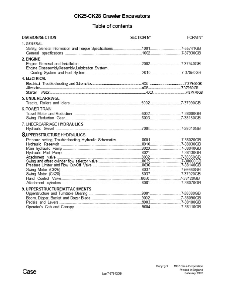
- CK25-CK28 Crawler Excavators
- Table of contents
- DIVISION/SECTION SECTION N FORM N
- GENERAL
- Safety, General Information and Torque
Specifications ..............................1001.
................................7-55741GB General
specifications ..................................
...............................................100
2.................................7-37930GB - ENGINE
- Engine Removal and Installation
..................................................
..............2002................................
.7-37940GB - Engine Disassembly/Assembly, Lubrication System,
- Cooling System and Fuel System ...................
........................................2010......
...........................7-37950GB - ELECTRICAL
- Electrical Troubleshooting and Schematics.........
........................................400J
.................................7-37960GB
Alternator........................................
..................................................
...........4002.................................7-
37980GB - Starter Motor....................................
..................................................
..........4003.................................7-3
7970GB - UNDERCARRIAGE
- Tracks, Rollers and Idlers........................
..................................................
..5002.................................7-37990GB - POWER TRAIN
- Travel Motor and Reduction .......................
................................................60
02.................................7-38000GB - Swing Reduction Gear..............................
..................................................
.6003.................................7-38150GB - UNDERCARRIAGE HYDRAULICS
- Hydraulic Swivel ................................
..................................................
........7004.................................7-380
10GB
Copyright
1995 Case Corporation Printed in England February
1995
Case
Lep 7-37912GB
2
Section
11 SAFETY INSTRUCTIONS, GENERAL INFORMATION AND
TORQUE SPECIFICATIONS
Copyright O 1991 JI Case Company Printed in
England Noverriaer 1991
J I Case
Lap 7-55741
3
1001-3
SAFETY
This sym6ol means ATTENTION ! BECOME ALERT ! YOUR
SAFETY IS INVOLVED. The message that follows the
symbol contains important information about
safety. Carefully read fhe message, Make sure you
fully understand the causes of possible injury or
death.
To prevent injury always follow the Warning,
Caution and Danger notes in this section and
throughout the manual. Put the warning tag shown
below on the key for the keyswitch when servicing
or repairing the machine. One warning tag is
supplied with each machine. Additional tags Part
Number 331-4614 are available from your service
parts supplier.
Before starting engine, study Operator's Manual safety messages. Read all safety 9ns on iriachine. Clear the area of other persons. Learn and practise safe use of controls before operating. It is your responsibility to understand and follow manufacturers instrucitons on machine operation, service, and to observe pertinent laws and regulations. Operator's and Serw"ce Manuals maybe obtained from your J.I. CASE dealer. Before starting engine, study Operator's Manual safety messages. Read all safety 9ns on iriachine. Clear the area of other persons. Learn and practise safe use of controls before operating. It is your responsibility to understand and follow manufacturers instrucitons on machine operation, service, and to observe pertinent laws and regulations. Operator's and Serw"ce Manuals maybe obtained from your J.I. CASE dealer.
If you wear clothing that is too loose or do not use tfie correct safety equipment for your jo6, you can be injured. Always wear clothing that 'ill not catch on objects. Extra salety equipment that can be required includes hard hat, safety shoes, ear protection, eye or face protection, heavy gloves and reflector clothing.
When worldnp in the area of the fan 6eIt with the engine running, avoid loose clothing if possible, and use extreme caution.
When doing checks and tests on the equipment hydraulics, follow the procedures as they are written. DO NOT change the procedure.
When putting the hydraulic cylinders on this machine through the necessary cycles to check operation or to remove air from a circui make sure all people are out of the rna .
See Other Side
Reason
B004
Read fhe operator's manual to familiarize yourself with the correct control functions.
Operate the machine and equipment controls from the seat position only. Any other method could result in serious injury.
Operate the machine and equipment controls from the seat position only. Any other method could result in serious injury.
Operate the machine and equipment controls from the seat position only. Any other method could result in serious injury.
This is a one man machine, no riders aIIow'ed.
!
Lep 7-55741
Issued 11-91
Printed in England
4
https//www.ebooklibonline.com Hello dear
friend! Thank you very much for reading. Enter
the link into your browser. The full manual is
available for immediate download. https//www.ebo
oklibonline.com
5
1001-4
mittens
when
When servicing or repairing the machine. Keep
the shop floor and operator's compartment and
steps free of oil, water, grease, tools, etc. Use
an oil a6sor6ing material and or shop cloths as
required. Use safe practices at all times.
Use insulated gloves working with hot pans.
Lower all attachments to the ground or use
stands to safety support the attachments
6efore you do any maintenance or service.
Some components of this machine are very heavy.
Use suitable lifting equipment or additional help
as instructed in this Service Manual.
Pin sized and smaller streams of hydraulic oil
under pressure can penetrate the skin and resv/I
in serious infection. If hydraulic oil under
pressure does penetrate the sixIn, seex medical
treatment immediately.
Maintain all hoses and tubes in good condition.
Make sure all connections ara tight. Make a
replacement of any tube or hose that is damaged
or thought to be
Engine exhaust fumes can cause death. If it
is necessary to start the engine in a closed
place, remove the exhaust fumes from the
area with an exhaust pipe extension. Open
the doors and get outside air into the area.
damaged. DO NOT use your hand to check for leaks,
use a piece of cardboard or w'ood.
When the battery elea ne is frozen, the battery
can explode if (1), you try to charpe the
battery, or (2), you try to jump start and mn the
engine. To prevent the battery electrolyte from
freezing, try to keep the battery at full charge.
If you do not follow these insfrocffofis, YOU Of
Others in the area can be injured.
When removing hardened pins such as a pivot pin,
or a hardened shaft, use a sofi head (brass or
bronze) hammer or use a driver made from brass
orbronze andasteel head hammer.
When using a hammer to remove and install
pivot pins or separate parts using compressedair
or using a grinder, near eye protection that
completely encloses the eyes (approved 9agIes or
other approved eye protectors).
Batteries contain acid and explosive
gas. Explosions can result from sparks, flames or
wrong cable connections. To connect the jumper
cables correctly to the battery of this machine
see the Operator's Manual. Failure to follow
these instructions can cause serious injury or
death.
Use suitable floor (service) jacks or chain
hoist to raise wheels or tracks off the floor.
Always 6lock machine in place with suitable
safety stands.
Issued 11-91
Printed in England
Lep 7-55741
6
1001-5
GENERAL INFORMATION SEAL RINGS, O RINGS AND FLAT
SEALS
CLEANING
Glean all metal components, except bearings, with
steam or white spirit. Do not use caustic soda
when steam-cleaning. After cleaning, dry and
oil the components. Clean oil lines with
compressed air. Clean bearings in kerosene, dry
them completely and oil them.
Always install new seal rings, O-rings and flat
seals, if removed. Lubricate seal rings and
O-rings with petroleum jelly.
SHAFTS
Check all shafts showing signs of damage or wear.
Check particularly to make sure that any surface
of the shaft in contact with bearings or seal
rings is not damaged.
INSPECTIONS
Carefully examine all disassembled components.
Replace all parts showing signs of wear or damage.
Light scores and scratches can be removed by
honing or with a buffing compound. Fast, abnormal
wear of components can be avoided by careful
examination and early detection of wear and
pitting.
SERVICE PARTS
Always use genuine CASE service parts. To order
service parts, see the Spare Parts Catalog and
remember to give the correct reference of the
necessary CASE part. No warranty claims will be
considered for failures involving parts which are
not of CASE origin.
BEARINGS
Check that bearings run freely. Replace bearings
that show signs of too much play or seizing.
Clean bearings in a good solvent or kerosene and
allow them to dry naturally. DO NOT DRY
BEARINGS WITH COMPRESSED AIR.
LUBRICATION
Never use oil or grease which is different from
that specified in the Operator's Manual or the
Service Manual. No warranty claims will be
considered for failures due to the use of wrong
oil or grease.
NEEDLE BEARINGS Before installing needle
bearings in their housing, remove any metal edges
inside or around the housing. When installing
bearings with a hydraulic press, grease the
inside and the outside of the bearing with
petroleum jelly.
GEARS Check all gears for signs of damage or
wear. Replace damaged or wom gears.
Issued 11-91
Printed in England
Lep 7-55741
7
Section
2002
ENGINE REMOVAL AND INSTALLATION
Copyright O 1992 J I Case Company Printed in
England May 1992
J I Case
Don 7-37940
8
2002-3
Removal and Installation STEP 1
STEP 5
Remove the Hydraulic Oil Reservoir, refer to
Section 8010.
Park the machine on hard level ground. Lower the
attachment to the ground. Release pressure in the
hydraulic circuits and stop the engine. STEP 2
STEP 6
Disconnect the battery, positive () terminal
first. NOTE For Installation, install and
tighten the negative () terminal first. STEP 3
Remove the Cab or Canopy, refer to Section
9004. STEP4
ut a container with a capacity of at least5
Litres under
the radiator drain valve and drain the
coolant. NOTE For Installation, install coo/am
to the corec/ level. STEP 7
2 lemove the bolts (1) and the protector
(2). NOTE For Installation, apply Loctite 271
to the 6oks and tighten to a torque of M12 - 77
to 90 Nm M16 - 166 to 197 Nm Remove the hood
mounting bolts (1) from the inside of the engine
compartment. NOTE For Installation, apply
Loctite 271 to the bolts (1) and tighten to a
torque of M10 - 48 to 56 Nm M12 - 77 to 90 Nm
Issued 5-92 Printed in England
Don 7-37940
9
2002-4
STEP 10 Remove the battery and the fluid level
sensor.
STEP 8
Remove the bolts (2) and slide the control box (1 Remove the bolts (2) and slide the control box (1
STEP 11
forwards. STEP 9
Disconnect and cap the radiator hoses (1) and
(2). STEP 12
. """ Disconnect and remove the gas
strut (1) on the hood. Support the hood on
suitable lifting equipment. Remove the
hood. Disconnect and cap the oil cooler hoses (1)
and radiator return hose (2). STEP 13
Remove the radiator/oil cooler assembly.
NOTE When the hood (1) is closed make sure the
catch (2) comes in close contact wit/? the
bracket (4). \I\then opening the hood (1) make
sure the catch (2) easi/y'comes off the
bracket(4), ifnecessaiy adjust with shims (5).
NOTE For Installation, make sure the radiator
(1) and fan (2) have the foIIOWlng clearances A
30 mm or more B 15 mm or more C 20 mm or
more
Don 7-37940
Issued 5-92 Printed in England
10
2002-5
STEP 17
STEP 14
z Disconnect the throttle cable (1), tachometer
cable (2), fuel hose (3) and clamp (4).
Disconnect and cap the hoses (1) and (2) from the
hydraulic pump.
NOTE For Installation, refer to Section 9003 for
throttle cable adjustment.
STEP 18
STEP 15
Support the engine on suitable lifting equipment.
Remove the engine mounting bolts (1).
Remove the cover next to the right control lever
stand. Disconnect the main electrical harness
from the engine.
NOTE For Installation, apply Loctite 271 to the
engine mounting bolts and tighten to a torque
of M10 - 48 to 56 Nm M12 - 77 to 90 Nm M14 - 124
to 147 Nm.
STEP 16
JR Disconnect and cap the heater hoses, (if
equipped).
Issued 5-92 Printed in England
Don 7-37940
11
2002-6 STEP 19
Carefully remove the engine from the
machine. NOTE For Installation, follow the same
procedure in reverse order. Open the heater
valve, situated on top of the engine, to allow
the coolant to circulate. Sta/t and run the
engine for approximately 5 minutes. Stop the
engine and check the coolant level, engine
oi/level and hydraulic oil level. Add coolant or
oil if necessary.
WARNING Never run an engine in an closed
building. Proper ventilation is required under
all circumstances.
Issued 5-92 Printed in England
Don 7-37940
12
2010-8
SHOP EQUIPMENT TOOLS
- TORQUE WRENCH, OEM 6474 AND OEM 6477
- VALVE SPRING COMPRESSOR, OEM 6414
- PISTON RING EXPANDER, OEM 6266
- SPRING TESTER, OEI\4 1282
- PISTON RING COMPRESSOR, OEM 6269
- PULLER, OEM 4212
- COOMNG SYSTEM PRESSURE TESTER, OEM 1347
- DEPTH MICROMETER, CAS10064-IM
- MICROMETER (0 to 25 mm), OEM 10057M
- MICROMETER (25 to 50 mm), OEM 10058M
- SMALL HOLE GAUGE SET. OEM 1023
- D!AL GAUGE, CAS 10066-1A
- AND MAGNETIC BASE, CAS 10149
- TELESCOPING GAUGE, OEM 1015
- TELESCOPING GAUGE, OEM 1017
- TELESCOPING GAUGE, OEM 1018
- TELESCOPING GAUGE, OEM 1019
- CYLINDER BORE GAUGE, OEM 10540
TOOLS TO BE MADE
200(7.87) 80(3.1 5)
3. SMALL END BUSHING DRIVER
4. CRANKSHAFT BEARING 1 DRIVER
2. IDLER GEAR BUSHING DRIVER
5. GOVERNOR GEAR HOLDER BUSHING DRIVER issued
6-92 Primed in England
Don 7-37950
13
2010-9
CYLINDER HEAD STEP 5
Removal and Installation STEP 1
Remove the drain plug and drain the engine oil.
Drain the coolant from the cylinder block. STEP
2 Remove the air filter assembly and
muffler. NOTE For Installation, install the
mufflergasket with the steel side facing the
muffler.
STEP 3
Remove the rocker cover retaining nuts. Remove
the rocker cover (1) and discard the gasket.
NOTE For Installation, install a new
rockercovergasket and tighten tfie retaining nuts
to a torque of 6.9 to 8.8 Nm (5 to 6.5 lb
It) STEP 6
Remove the altemator (1), fan belt (2) and
fan. NOTE For Installation, tighten the fan
be/ito 7 to 9 mm deflection at 98 N. STEP
4 Remove the rocker shaft retaining nuts and
remove the rocker shaft assembly. Remove the push
rods. NOTE For lnstallation, flghten the
rockershafiretaining nuts to a torque of 21.6 to
26.5 Nm (16 to 19.5 Ib ft)
Remove and cap the fuel injection pipes. Remove
the fuel overflow pipes. Remove the nozzle holder
assemölies (1). NOTE For Installation, tighten
the nozzle holder assemblies to a torque of 49 to
68.6 Nm (36 to 50.6Ib It) and the
fuelinjectionpipenuts to a torque of24.5to 34.3
Nm (18 to 25 lb ft)
Don 7-37950
lssued 6-92 Printed in England
14
2010-10 STEP 7
Disassembly and Assembly STEP 9
14 18 10 O.. .O
6
3
11
2 O
7 O
15 O
o
O 17
O o O 9 8 13 5 J2
16
loosen the clamp and remove the coolant return
pipe. Remove the cylinder head retaining bolts
(14 to 1 for 3 cylinder engines) or (18 to 1 for
4 cylinder engines) and remove the cylinder head.
Remove and discard the gasket.
NOTE For Installation, install a new cylinder
head gasket. Install and tighten the cy//nder
head bolts (1 to 14 for 3 cylinder engines)or (1
to 18 for 4 cylinder engines) to a torque of 63.7
to 68.6 Nm (47 to 51 lb It).
Remove the valve cap (1). Use a valve spring
compressor to compress the valve spring, remove
the collet (2), retainer (3), valve spring (4)
and valve (5). Remove and discard the seal (A).
NOTE Check the torque of the cylinderhead bolts
after approximately 30 minutes running.
NOTE For Assembly, install a new seal (A).
STEP 8
Remove the tappets (1) from the crankcase. Put
identification marks on the tappets (1) for
installation. NOTE Coat the tappets (1) will?
c/ean engine oil before installation. NOTE For
Installation, follow the same procedure in
reverse order.
Don 7-37950
Issued 6-92
Printed in England
15
2010-11
CRANKCASE STEP 4
Disassembly and Assembly STEP 1
Remove the engine stop solenoid (1). Remove and
discard the gasket.
Remove the fuel feed pump (1) and tachometer
drive housing plate.
NOTE For Assembly, install a new engine stop
solenoid gasket.
STEP 2
STEP 5
Remove the water pump assembly. Remove
and discard the gasket.
Remove the speed control plate (1) and governor
spnngs.
NOTE For Assembly, install a new water pump
gasket.
NOTE 7ake care not to drop the governor springs
into the crankcase.
STEP 3
NOTE For Assembly, insiatl a new speed control
plate gasket.
Remove the front gear cover. Remove and discard
the gasket. NOTE For Assembly, install a new
front cover gasket.
Don 7-37950
Issued 6-92
Printed in England
16
2010-12 STEP 6
STEP 8
Align the control rack pin (3) with the notch (1)
in the crankcase and remove the injection pump
(2). Remove the injection pump shims, make a note
of the number of shims removed.
Remove the oil pressure pump. Remove the snap
ring (1) from the governor shaft. Remove the
governor shaft assembly (2).
- NOTE ForAssembiy, make sure the controliackpin
(3) is located in the groove of the fork and
ihrust lever. - IMPORTANT Install the same amount of shims
between the crankcase and injection pump, as
removed in Step 6. Check the injection timing,
adding or removing one shim retards or advances
ihe injection timing by 1.5 degrees. - STEP 7
- SNAP RING
- GOVERNOR SHAFT
- GOVERNOR SHAFT BUSHING
- Before installing the governor shaft (2) into the
crankcase, install a new bushing (3) using the
Bushing Installation Driver, refer to Tools to be
Made, Page 8. Install the shaft (2) and snap ring
(1), check the shaft (2) rotates freely.
Remove the fuel camshaft retaining bracket (1).
Remove the fuel camshaft (3) and timing gear (2).
Issued 6-92 Printed in England
Don 7-37950
17
2010-13
STEP 9
STEP 11
lemove the cover (1), spring (4) and shaft (5).
Remove
Remove the snap ring (A) and idler gear (1).
Remove the camshaft retaining bolts (8) and
carefully remove the camshaft gear (3) and
camshaft (2).
the spacer (2) and bearing (3). Remove the levers
(6) and (7.
NOTE For Assembly, install a new gasket onto the
cover (1).
NOTE For Assembly, make sure the timing marks
are aligned, as shown.
STEP 10
nstall the lever (6) to the RH side of the fuel
limit bolt (8), as shown.
Don 7-37950
Issued 6-92 Printed in England
18
2010-14 PISTON AND CONNECTING RODS Removal and
Installation STEP 2 STEP 1
Remove the oil pan retaining screws. Remove the
oil pan, remove and discard the gasket. Remove
the oil strainer (1), remove and discard the
o-ring. NOTE For Installation, install a new
a-ring onto the oil strainer, install the oil
strainer. Install a new oil pan gasket and
install the oil pan. When tightening the oil pan
retaining boils, tighten diagonally from the
center.
Remove the connecting rod cap retaining screws.
Remove the connecting rod cap. NOTE For
Installation, coat the ietaining screws lightly
with clean engine oil. Tighten to a torque ot41.2
to 46.1 Nm (30.4 to 34 lb fi). NOTE For
Installation, align the identification marks on
the connecflng rod and cap. STEP 3
Turn the flywheel until the No. 1 piston is at
top dead center. Remove the piston and connecting
rod.
Don 7-37950
Issued 6-92 Printed in England
19
2010-15
STEP 4
STEP 7
(d)
(b)
osition the piston rings on the piston, as shown.
nstall the connecting rod (7) into the piston (2)
with the
casting mark (9) and identification numbers (10)
in the same direction.
STEP 5
STEP 8
180
Use a ring compressor (1) and install the piston
and connecting rod using a hammer shaft, as
shown. NOTE Make sure the identification marks
on the connecting rod and cap are facing ihe
inecfion pump. IMPORTANT DO NOT interchange
the pistons and liners. Disassembly and
Assembly STEP 6
a PISTON PIN HOLE b. TOP RING GAP
c. SECOND RING GAP d. OIL RING GAP
Install the oil ring onto the piston with the
expander joint (11) on the opposite side to the
gap (12). Install the remaining piston rings with
the manufacturers marks (13) facing the top of
the piston.
Remove the piston rings (4, 5 and 6). Remove the
snap ring (3) and piston pin (1). Remove the
connecting rod (7) from the piston (2).
Don 7-37950
Issued 6-92 Printed in England
20
2010-16
CRANKSHAFT STEP 3
Removal and Installation STEP 1
Lock the flywheel and remove the retaining bolts.
Use a suitable extractor to remove the
flywheel. NOTE For Installation, tighten the
retaining bolts to a torque of 53.9 to 58.8 Nm
(39.8 to 43.4 lb ft). STEP 2
Remove the crankshaft bearing retaining screws
(5) and carefully remove the crankshaft. NOTE
For Installation, install the ciankshaft with
the holes in the 6eanng case (2) aligned with
the cylinder block (1). Install and tighten the
remaining screws (5) to a torque of 49 to 53.9 Nm
(36.2 to 39.8 lb ft). Check the side clearance of
the crankshaft, refer to Specifications, Page 4.
Remove the bearing case retaining screws and
remove the bearing case (3). Remove and discard
the oil seal. NOTE For Assembly, install a new
oil seal. Install a new gasket onto the fearing
case. Install the fearing case (3) with the mark
UP(4), in the position shown. Tighten the
retaining screws diagonally to a torque of 29.4
to 34.3 Nm (21.7 to 25.3 lb ft).
Don 7-37950
Issued 6-92 Printed in England
21
2010-17
Disassembly and Assembly STEP 4
STEP 5
(C) (B)
Clean the oil passage in the bearing case. Apply
clean engine on the thrust bearings and bearings.
Make sure the bearing cases are installed on the
crankshaft in the same position as removed.
lemove the two screws from the bearing case (1).
Remove the bearing case (1) from the crankshaft.
Remove the thrust bearing (3) and bearing from the
bearing case. Repeat procedure for the remaining
bearing cases.
NOTE For Assembly, make sure the/bce of the
bearing case marked FLYWHEEL is facing towards
the flywheel and the oil grooves in the thrust
bearings lace onwards from the bearing cases.
Don 7-37950
Issued 6-92 Printed in England
22
Suggest If the above button click is invalid.
Please download this document first, and then
click the above link to download the complete
manual. Thank you so much for reading
23
2010-18
CYLINDER HEAD STEP 2
inspection
Install the valve into the cylinder head and
using a depth micrometer measure the distance
between surface of the valve and cylinder head.
If the measurement is not within specification,
replace the valve. If the measurement is still
greater than specification check the valve seat
face and correct if necessary. Valve recess
0.05 to 0.15 mm (0.4 mm maximum) STEP 3 Valve and
Valve Guide
Thoroughly clean the surface of the cylinder
head. Check the cylinder surface for warpage,
using a straight edge and feeler gauge in the
positions shown. NOTE II the measurement is more
than 0.05 mm the cylinder head must 6e machined
or replaced. IMPORTANT It the cylinder head has
been machined, refer to Step 2 to check the va/ve
recess.
Measure the outside diameter of the valve stem
and the inside diameter of the valve guide. If
the clearance is greater than 0.10 mm, replace
the valve guide or valve. Refer to
Specifications, Page 4, for the O.D. of the valve
stem and I.D. of the valve guide.
Issued 6-92 Printed in England
Don 7-37950
24
https//www.ebooklibonline.com Hello dear
friend! Thank you very much for reading. Enter
the link into your browser. The full manual is
available for immediate download. https//www.ebo
oklibonline.com
Recommended
