
CASE IH 955 1055 Tractor Service Repair Manual Instant Download PowerPoint PPT Presentation
Title: CASE IH 955 1055 Tractor Service Repair Manual Instant Download
1
Ii
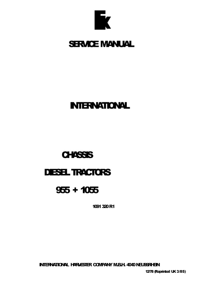
SERVICE MANUAL
INTERNATIONAL
CHASSIS DIESEL TRACTORS 955 1055 1091 320 R 1
INTERNATIONAL HARVESTER COMPANY M.B.H. 4040
NEUSS/RHEIN 12/78 (Reprinted UK 3/85)
2
TABLE OF CONTENTS
Section
Page
Introduction 34
General Technical Data
Wheels and Tires 612
Rear Axle 1317
Service Brake 1824
Parking Brake 2527
Pneumatic Trailer Brake 2835
Front Axle and Bolster 3639
Front Wheel Drive Axle APL 3052 4050
Front Wheel Drive 5155
Dual Clutch 5663
Engine Removal and Installation 6465
Accelerator Linkage and Bowden Control 66-67
Radiator 68-69
Air Cleaner 70
Fuel Tank 71-72
Cab 73-77
Electrical Equipment 7885
Special Tools 8688
Index 89
1 091 320 R 1 2.78
- 2 -
3
INTRODUCTION General Key to Symbols
The following symbols are shown on some IIlusts.
in this manual.
This Chassis Service Manual has been prepared as
part of and to complete a series of manuals
such as for engine, transmission, hydrostatic
steering and hydraulic draft control for the
guidance of the skilled serviceman who is
responsible for the repair and overhaul of
Internatio- nal Tractors.
Replace on every tear-down
Use Special Tool
In addition to being a comprehensive workshop
guiae nis Service Manual also points out the
various possibilities of re-equipment -and
replacement to improve the tractor's performance
for a specific application. Special Tools
A minimum of special tools is required. For
details see corresponding section of this Service
Manual and/or Parts Catalog.
For general directions e.g. special torques etc.
see Service Manual General Service Information.
SI Measurements A standard of measurement known
as International System of Units (SI) has been
adopted for world-wide use. These units are used
throughout this manual. E.oylish Equivalent
mm milimeter cm centimeter cm3 cubic
centimeter m3 cubic meter liter kg
kilogram kPa kilopascal MPa Megapascal N
Newton daN dekanewton Nm Newton rr.eter
daNm dekanewton meter of degrees-Celsius kW
kilowatt I/min liter/minute km/h -
Kilonneter/hour 1/min
0.039 inches 0.39 inches 0.06 cubic inches 35.31
cubic feet 1.057 qaart 2.205 pounds
weight 0.145 psi 145 psi 0.225 pounds force 2.25
pounds force 0.738 foot pounds force 7.38 foot
pounds force OFahrenheit 1.8 x OC 32 1.34
horsepower 0.219 gallons per minute 0.621 miles
per hour rpm
091 320 R 1 12.78
.3-
4
https//www.ebooklibonline.com Hello dear
friend! Thank you very much for reading. Enter
the link into your browser. The full manual is
available for immediate download. https//www.ebo
oklibonline.com
5
INTRODUCTION
Safety Precautions
This symbol is used to call your attention to
instructions concerning your personal safety. Be
sure to ob- serve and follow these instructions.
- Caution is the most effective safeguard against
accidents during a repair. - Keep the place of repair, surrounding area as
well as ladders, tools, etc. free of oil and
grease. - When working on rear axle or removing engine,
block front axle with wooden wedges to prevent
tilting. - Be extra careful in the vicinity of a running
engine, fan blades or exposed shaft ends. Wear
tight clothing. - Never attempt to loosen or tighten hose couplings
or fittings of air pressure or hydraulic system
while the engine is running or power cylinders
are under pressure. - Beware of hot oil and coolant when draining.
- Keep your tools in good condition. Worn or
damaged tools may cause accidents or spoil good
machine parts. - Keep lifting equipment in proper order. Do not
overload! Tie heavy parts securely before
lifting. - Take care when removing preloaded springs! Keep
under control until spring is relieved. - Wear approved protective goggles when grinding
and cleaning with compressed air.
For wdding repairs carefully observe all safety
regulations.
1 091 320 R1 12.78
-4-
6
GENERAL TECHNICAL DATA
Service Brake
Hydraulically operated, twin disk type wet brake,
acting on the rear wheels.
Parking Brake
Mechanical band and drum type acting on the
differential drive
Clutch Dual Clutch Make
F S
Model Engine Clutch PTOClutch
-singTetypedry disk - single type dry disk
Front Wheel Drive Axle Make Type
ZF APL 3052
Advanced drive of front wheels in respect to rear
wheels in
5 to -1
Ratio front to rear axle
1.376
Dimensions (in mm) Dimensions (in mm) 955 955 1055 1055
Standard Four wheel drive version Standard Four wheel drive version
Length overall (with three-point suspension hitch) Length overall (with three-point suspension hitch) 4194 4229 4194 4229
Width overall (to outside edge of rear wheel fenders) Width overall (to outside edge of rear wheel fenders) 2306 2306 2306 2306
Height overall (to top of exhaust muffler) Height overall (to top of exhaust muffler) 2744 2884 2778 2918
Height overall (to top of cabin) max. Height overall (to top of cabin) max. 2649-2675 2649-2675 2649-2699 2649-2699
Wheel base Wheel base 2627 2587 2627 2587
Ground clearance (under front axle) Ground clearance (under front axle) 512 412 512 412
(under transmission) 401 401 401 401
Turning radius, with steering brake applied Turning radius, with steering brake applied 4400 4700 4400 4700
without steering brake applied without steering brake applied 5050 5350 5050 5350
/\lore Dimensions apply to the following tire
equipment
Front 7.50 18 AS Rear 18.4/15 34 AS 6 PR FWD
11.2/10 28 AS 6 PR with 18.4/15 34 AS 6 PR
09J 320 R1 12.78
7
M Al
WHEELS AND TIRES
Removal
General
To ensure maximum tire life and satisfactory
performan- ce of wheels, rims and disks must be
in good condition, i.e. out-of-round as well as
out-of-true must not exceed specified limits and
tread lugs on rims must not be loose or
distored. The above faults are mainly due to a
slight warpage or distortion of the disk or rim,
caused by incorrect moun- ting of wheel weights
or by hitting solid obstacles with the wheel
side. Four wheel drive tractors can be equipped
with various tire combinations, see charts on
following pages.
It is important to adhere to these tire
combinations.
I IIust. 1 Rear wheel
Loss of power, excessive tire wear and damage to
the power train may result if the relationship
between front axle and rear axle is disturbed by
an unauthorized tire combination.
- R im nuts
- Wheel nuts or bol ts
- R im
- - Disk
- Axle flange
Caution! Never attempt to mount tires with- out
proper equipment and knowledge to use it.
Loosen nuts (5) IIlust. 1.
The following tools should be available Jack of
sufficient capacity 2 tire levers (one cranked
end) 1 Icng lever 1 removing tool (to loosen
beads) 1 rubber hammer 1 pressure gauge tire
lubricant, soap suds or a similar gliding agent.
Jack up until wheels clear the ground and safely
support the tractor.
Remove wheels and deflate tires. Drain off liquid
weight if tires are water-ballasted (refer to
Operators Manual)
Loosen tire beads from rim flanges all around use
ng a suitable commercial tool. Never attempt to
loosen beads with hammer and wedge because damage
to rim and beads may result.
Be sure the shop floor is clean and dry. Oil and
grease affect tires and tubes.
o
For details, such as tire pressure, loading
capacity, speed limitations, etc. refer to the
tire manufacturer's instruc- tions or see your
tire representative. Specifications
Maximum permissible Maximum permissible
out-of-round out-of-true
Wheel disks 0.4 2.0
Rear wheel rims 5.0 5.0
Front wheel rims (also on four-wheel-drive tractors) 2.5 2.5
lMust
- Valve
- Tire lever
- Wooden block
- Opposite beads
Torque Data
daNm
R im nuts, front wheel FWD 30
R im nuts rear wheel M 14 18
R im nuts rear wheel M 8 35
Risk nuts rear wheel 35
Uisk bolts front wheel 151b
Disk nuts front wheel FWD 35
Dual tires, nuts 1618
Starting near valve (1) IIlust. 1a work the bead
over the rim flanpe using two tire levers (2)
Make sure opposite beads (4) are well in the rim
base. Place tire wall on wooden block (3) to
facilitate this work. Remove tube Use a long tire
lever (1) Illust 1b to work the second bead over
the rim flange. It is good practise \o apply some
soap suds to facilitate removal An assistent may
drive the bead ( I) over the rim flange.
1 091 320 R1 12 78
- 6 -
8
WHEELS AND TlFtES
e
Before remounting tire on wheel, clean rust from
rim base and bead seats by wire bushing or sand
blasting. Paint these surfaces, preferably with
one coat of zinc chromate, red lead, or a good
grade of aluminium paint, and allow paint to dry
thoroughly. Inspect the tire for tear and other
damage, giving special attention to the bead and
side wall areas. Recapping is remommended only if
the cord body is still in good condition. If in
doubt, consult a reputable recap- per firm.
IIlust. 1b
- Tire bead
- Long tire lever
Mounting
Never lever in line with your head.
It is important to match tires and rims
correctly. Rims have a rim size code near the
valve hole. See also manufacturers matching
records. Make sure the arrow on the tire points
in forward drive direction (self-cleaning effect).
Cleaning, Inspection and Repair
Note Use soap suds as mounting a d.
Mounting of Tires with Inner Tube Clean rim and
apply some soap suds to tire beads and rim
flanges. Place rim with valve hole up. Apply some
talcum powder and install tube into tire so that
valve stem can be inserted into valve hole later
on.
IIlust. 1c
Slightly inflate tube to prevent crumbling. Pull
the tube (1) Illust. J d out of the tore opposite
the valve stem (2) to prevent damage.
- R inn profile
- - R inn lug
- R ivets (on some applications welded)
- R im base
- Bead seat
- Rim flange
2
Bolt rear wheel disks, rims and front wheels to
their respective hubs or axles and check for
out-of-true on flange (6) Illust. 1c and
out-of-round on bead seat (5) while spinning the
wheel. When checking run-out on wheel disks.
measure on the outer diameter. lnspect wheel
bolts and ball flange nuts for serviceability.
Check wheel disks for cracks around holes and
replace with new parts, if necessary. Do not
attempt welding! Check each welding seam on rim
lugs for cracks.
IIlust. 1d
- Tube
- Valve
\1 necessary cut out cracks by grinding and
reweld.
R inns and wheel disks are cold extruded
sections. No heat, whatsoever, must therefore be
used for straighte- ning!
Lever the thus cleared lower bead over the rim
flange using a cranked end tire lever. Use a
hammer to help the last bead section over the rim
flange. Make sure the inner tube is in the tire
without twist and the valve stem is pro- perly
secured. Fit the upper bead in the same way
start- ing on the far end of the valve see
IIlust. 2. Support the lower bead of the tire
with a wooden block on the oppo- site side when
working over the last section. Be sure tire beads
are in all around.
Dents and other deformations on the rim flange
are easy to be taken out.
Out-of-true can be corrected, if within
reasonable limits. Excessive out-of-round calls
for replacement o1 the rim.
091 320 R 1 2.78
-7 -
9
VVHEELSANDTIRES Be sure that tire seats
properly on its rim before inflating to max.
assembly pressure. Recheck correct seating of
beads. When properly moun- ted the centering
marker on the tire should be an even distance to
the rim flange all around. Deflate to specified
operating pressure. For water ballasting refer to
Operator's Manual. Refer to the manufacturers
instructions for cold weather precautions. lMust.
2 Protect inflation valves with dust caps.
Maunting of Tubeless Tires Use a new valve
assembly and install with a commercial fitting
tool. Apply some gliding agent to the tapered
sec- tion of the valve stem.
Mounting of l/!/heeIs
Tighten bolts and nuts to the torque values shown
under "Torque Data. Retighten wheel nuts or
bolts after 20 operating hours.
1t is good practice to apply some soap suds to
beads and rim flanges. Be careful not to damage
beads or rim flan- ges. Use good tools to ensure
tight sealing. Fit tire in the same way as
described at tire mounting with inner tube.
Assemble dual tires using the spacer hexagon
provided for this purpose and the specified
square neck carriage bolts (5) Illust. 3.
Retighten these bolts after the trial run and
after each day o1 operation, until they have ta-
ken a set. Torque of theses bolts must not be
exceeded!
Inflation
Replace lock washers (6) that have lost
tension. As a rule tire beads will seal on rim
flanges. Removing stem of inflation valve makes
air blast more effective. Should this present
problems or beads do not stay in contact roll
the wheel assembly somewhat. This usual- ly helps
to start up inflation. If not use a commercial
tightener strap around the tire tread to spread
beads against rim flanges. To seat tires properly
on their rims inflate tire to twice of operating
pressure. Take care that beads are not twisted or
distorted, but seat properly on both rim fanges.
If not do not inflate above max. operaGng
temperature. ReMeve pressureand correct the tire
seat on the rim.
If an improperly mounted tire is inflated above
max. operating pressure there is a danger of
stretching the wire core of the bead or even
breaking it which might cause accidents.
Illust. 3 Mounting of dual tires
- Inner wheel
- Outer wheel
- Disks
- Spacer hexagon
- Square neck bolt
- Lock washer
- Nut
- A 29 mm minimum
Check coat of tire lubricant on beads and improve
where
1 091 320 R1 12.78
10
II
WHEELS AND TIRES
Tire Combinations, 25 km/h Version F-I4/D-Tractor
s
AS-Farmer
a
!CON TI DUNLOP
T 84 A
d
9
T 33
5
T 32
w
f
0 N
z B
F 151
FIPES TONE
ATC
F-UL DA
AS-Pionier
8
2
FR I25 R
GOODPICH
Powergrip B
Y
P
F
k
G 800 Traction
ST
GOOD YEA P
TSG
SGAS
b
R
A
Vl0 Super 5i0
KLEBE R
Vf0 Super- Trocsol
h
ME TZEL ER
A 7
6
Bibogrip 3 AK 6
e
MICHEL IN PHOENIX
S
L
r
Z
3
SEMPEP IT
M P
M l7l
TM 52 AS Agrar
m 10
VEI TH PIREL LI
T
1
TSG R TT
VRED ESTEIN
Z
0
G
\ PP
8 6 6 6 6 8 6 6 6 6
VOPDER REIFEN FRONT TI R ES PNEUS A VANT
I
Explanation of Tire Combinationchart Only
front and rear tires with the same letter and/or
the same number must be used. Example
size PR make letter
Rear tire 18.434 8 Dunlop T32 H
Front tire 11.228 6 Good Year SGAS
1 091 320 R1 12.78
- 10 -
11
WHEELS AND TIRES
CONTI AS-Farmer AS-Farmer TXYZ abcd PQV CDERS fprtuv 5,9 GHIJK Limns w I, 2, 4 BHIJK Lnsw I, 2, 3, 4
Agrar Agrar Agrar FHIJK Lnsw I, 2
OUNLOP T 101 Dylon T 101 Dylon ASTU VW frtuv 6,7,8 CDEMP ORSprt uv 5, 9 f--GHIJK Lnsw 1,2,3
TS2 TS2 TS2 H !9
F-IRESTONE F UI F UI IKL kn
GOOD ilCH FR 125 R FR 125 R CDEPR SUfprt uv 8, 9 BIJKLN Ohknw l,2 FGH me
ST ST ST ASTU VW frtu 6,7,8 CDEIL MPOSh kpr 5, 9 FifiHlJK Lmnsw I, 2, 3, 4
GOOD YEAR TSG TSG FHJ 4
SGAS SGAS SGAS FHJ
KLEBER Vl0 Super 50 Vl0 Super 50 AUW nu 6,7,8 BIKLO hkn S gi
METZELER A7 A7 A TUVW tu 6,7,8
MICHELIN Bibagrip Delta 3 Bibagrip Delta 3 TVXYZ abcdeq v 6,8 CDEIMPO RSUfhkp rtuv 5, 8 BFifiHlJKL NOhkns w I, 2, 3, 4
SEMPERIT M l7l M l7l TUVXYZ abcde qv 6 BHIJKL nsw I, 2, 3, 4
VEITH PIRELLI VEITH PIRELLI rM s2 CDEIPR STUfrt uv 6, 7, 8 A FifiHIJL mns 4, 10
VEITH PIRELLI VEITH PIRELLI AS-Agrar CDEIMP ORSkp r 5,9 BHIJKL Nnsw l,2,4 BHIJKL nsw I, 2, 3, 4
VREDESTEIN TSGR TSGR CDEPRS Ufprtu v 8 BIJKLN Ohknw 1 2 ii AFGH gims
PR 8 8 8 8
HINTERREIF-EN REA R TIRES PNEUS ARRI RE HINTERREIF-EN REA R TIRES PNEUS ARRI RE HINTERREIF-EN REA R TIRES PNEUS ARRI RE I I I
1 09J 320 R 1 12.79
- 1 J
12
WH EELS AND TIRES Tire Combinations, 30 km/h
Version rwo-rralttors
CONTl AS-f'armer AS-f'armer R
T 32 T 32 T 32 A
DuNLo DuNLo r ss
T 84 A T 84 A T 84 A
GOODRicH FR l2Ifi R FR l2Ifi R L
SGAS SGAS SGAS C
ifiOOD YEAR TSG TSG H
ST ST ST /
METZELER A 7 A 7 D
SEMPER IT M 171 M 171 c
VEITH PIRELLI AS Aprar AS Aprar N B
vein-i PiRELLI TM 52 TM 52 E
VREDESTEi/v rso R rso R
PR 6 6 6 8 6 6 6
VORDERREIFEN F-RONT TIRES PNEUS AVANT VORDERREIFEN F-RONT TIRES PNEUS AVANT VORDERREIFEN F-RONT TIRES PNEUS AVANT I
CONTI AS-farmer CONTI AS-farmer AKLO BDER BDR
OUNLOP Agrar DR
OUNLOP T 101 Dylon AFKLMOP CKLO BDR
FIRESTONE F fS7 FIRESTONE F fS7 BDR
GOODRICH OR l25 R GOODRICH OR l25 R AKLM BDOR BE
GOOD YEAR ST GOOD YEAR ST AFKLMOP BCO BER
KLEBER V l0 Super 50 KLEBER V l0 Super 50 AKLMO BDOR
MICHELIN Bibagrip Delta 3 MICHELIN Bibagrip Delta 3 FGHIJNOP ABCKLMQ BDR
SEMPERIT." M 171 SEMPERIT." M 171 FGHIJ MNOP BDR
VEITH PIRELLI AS Agrar PER BCO BDR BDR
VEITH PIRELLI TM 52 ABKLMOP PER
VREDESTEIN TSifi R VREDESTEIN TSifi R AKLM BDOR BE
PR 8 8 8 8 8
HINTERREIyEN RNA R TIRES PNEUS AHRI/RE HINTERREIyEN RNA R TIRES PNEUS AHRI/RE 8 I I I
Explanation of fire Combinationchart Only front
and rear tires with the same letter must be
used. Example See 25 km/h Version
1 091 320 R 1 12.78
- 12-
13
REAR AXLE
e
General Each rear axle and final drive is
lubricated by its own oil bath. Due to the
reduction ratio in the planetary units high
torque power results at the rear axle end shafts,
protec- t 9 the transmission and differential
from undue mecha- nical stress and wear. Gear
ratio of final drive is 17.5. Tighten rear axle
mounting bolts after the tractor has been approx.
20 hours in operation, following a repair.
A mounting tool made in accordance with Illust. 4
ma- kes removal and installation of rear axle
more conveni- ent.
llust. 5
Remove support (J ) Illust. 6 Remove rear wheel,
fender (2) and three-point linkage as far as
necessary. Remove oil drain plug (3) and allow
rear axle oil to drain.
12_
IIIust. 4 Mounting tool
Illust. 6
- Support
- Fender
- Oil drain plug
- - Washer welded mm
- 25
- 160
- 245
- 345
- - 205
- 170
- 66
- Oil filter and oil level plug
- Axle carrier
mm 9 32 dia. 10 60 dia. 11 40 12
10 13 16 dia. 14 55
Remove cap screws (1) IIlust. 7 except the upper
one to hold the axle carrier in place.
A typical rear axle is shown on the following
IIlusts. The design may differ slightly from the
axle instalfed. The re- pair procedure is the
same.
Removal and Disassembly Jack up and support the
tractor ur.der transmission case.
Block front axle with wooden wedges to prevent
tilting, see Illust. 5.
Illust. 7 2 Breather filter
1 Cap screws
T 091 320 R 1 TZ78
- 13 -
14
REAR AXLE
Take the weight of the axle in a hoist as shown
in IIlust 7 or with mounting tool (6) IIlust 8.
Instal led on a 1\ oor jack (7). Remove the
uoper cap screw and pull the ax Ie carrier off be
planetary ring gear 11).
lMust 10 Arrow Crchp
- Illust. 8
- Planetary ring gear
- Spacer flange
- - Brake housing
- Differential shaft
- Axle carrier
- Mounting tool
- Floor jack
Illust. 11
- Special pliers, see Parts Catalog
- Planetary final drive assembly
- Planetary ring gear
- Axle carrier
Mark position of planetary ring gear (1) Illust.
9 to spa- cer flange (2). Remove ring gear as
shown in Illust. 9.
IIlust 9
Illust 12
- -- Planetary ring gear
- - Spacer flange
- Markings
- Round stock, 80 x 120 mm
- Axle carrier
- Axle shaft
Unseac circlip Illust. 10 using special pliers
(1) Illust. 11 and lihout planetary final drive
assembly together with circlip.
Carefully bump the shaft end face onto a suitable
piece of round stock (1) Illust. 12 until the
carrier drops off the shaft.
1 091 320 R 1 12.78
- 14-
15
M
REAR AXLE
Remove circlip (2) Illust. 14 and press out
bearing (1). Remove circlip (3).
2 q
Illust. 13
- Axle carrier
- Axle shaft
- Spacer ring
- Ball bearing
- Oil seal
- Illust. 15
- Thrust washer
- Needle bearings
- Planetary pinion
Remove bearing (4) Illust. J3 using a suitable
puller tool. Remove seal (ST.
- Planet carrier
- Roll pin
- Pinion shaft
To remove planetary pinions (6) IIlust. 15 drive
roll pins (2) into shafts (3) far enough to
permit pressing the lat- ter out of their seats.
Cleaning, Inspection and Repair Clean rear axle
parts and inspect them for wear and da- mage.
IIlust. 14
- Inner bearing
- Circlip
Change planetary pinions (6) IIlust. J 5 and
needle bear- ings (5) as a set only.
3 Circlip
091 320 RI 12.78
-15-
16
5 e Reassembly and Installation
REAR AXLE
Clean breather filter (131 Illust. 16. If wear
ring (3a) shows signs of scouring or if the seal
has worked into its face the ring must be
replaced.
16 18 20 17
1314.
19
2122 17
3a
(,1112
7 8
998O8-BO
28
3A2O4/2025
22 25
27
Illust. 16
- Planet carrier
- Pinion shaft
- Packing ring
- Breather filter
- Roll pin
- Cap screw
- Lock washer
- Thrust washers
- Needle bearings
- Planetary ring gear
- Wheel nut
- Axle sha.ft
- Oil seal. 3a Wearzing
- Ball bearing, outer
- Axle carrier
- Spacer ring
- Circfip
- Ball bearing, inner
- - Circlip
- Roll pin
- Spacer flange
- Planetary pinion
- Circlip
- Differential shaft
- Packing ring
- Drain plug
- Brake piston
- Filler and oil level plug
1 091 320 R1 12.78
- 16 -
17
REAFI AXLE
Install bearing (4) and oil seal (3) into axle
carrier as shown in Illust. 16.
Prior of reassembling planetary final drive
assembly, in- sert circlip (23) Illust. J6 into
planet carrier (10). Place circlip in such a way,
that it can be engaged after final drive assembly
is in place.
Insert circlip (7) and press in rear axle shaft
(2).
Slide spacer ring (6) onto rear axle shaft.
Assemble planetary pinions in sequence of re1.
nos. shown in Illust. 18.
Press the inner ball bearing (8) fully down onto
its shaft seat, using a suitable hollow drift on
the inner race. See Illust. J7.
Slide the planet carrier onto the rear axle shaft
splines and secure with circlip (23) Illust..16.
E 9 0
Illust. 17 Installation of inner ball bearing (8)
Illust. 16
- Hollow drift
- Ball bearing
Illust. 19
When inner ball bearing is properly seated,
install circlip (9) Illust. 16. 6 4 2 4 5
- Differential shaft
- Roll pins
- Bolts
- Spacer flange
- Automatic piston return
- Brake piston
Install roll pins (2) Illust. 19. Apply a film of
liquid sea- ler to sealing faces and install
planetary ring gear (19) Illust. 16 onto spacer
flange (4) Illust. 19. Observe mar- kings (3)
Illust. 9 made during disassembly.
Insert differential shaft (1) Illust. 19. Install
axle carrier. Tighten cap screws to 11 daNm in a
crosswise sequence. Fill up with recommended
oil Install all remaining parts. Make a test run.
Illust. 18
- Planet carrier
- Planetary pinion
- Needle bearings
- Thrust washers
- Pinion shaft
- Roll pin
1 091 320 RI 1278
- 17 -
18
SERVICE BRAKE
389
38
'
9
8 11
1O
2
1 4
13
18,,g 17
20
23 26
16 14
37
27
154jy . 35 31
28
26
27
t 29 26
36
Illust. 20 Brake system
12 Steering brake valve 17 Master brake
cylinder
21 - Brake booster 36 Spacer flange
1 091 320R1 12.78
-18-
19
SERVICE BRAKE General The brake is a
hydraulically operated, self-adjusting, twin disk
type. It is wet, i.e. it runs in the oil bath of
the rear axle. In the case of hydraulic pump
failure the brake system is still operable
however without brake booster assistance.
Fz
h h
Illust. 21 Brake Booster
M Test connector h41 Edges controlling flow to
P Pressure port from hydraulic pump. boost camber AC
R Return line pon (1.5 I/min when brake applied) e-e1 flow restriction to hydraulic
Z Outlet port to hydraulic system system oil
FI Pedal force AC Boost chambers
F2 Boost force to main brake cylinder g Booster pinion acting on
N Neutral flow master cylinder
Technical Data
Specifications (Dimensions given in
mm) Permissible backlash between splines of brake
disk and differential shaft
new condition 0.135
(Brake booster) 0.054
Brake pedal effort reduction Permissible wear 0.5
ratio 12 Return spring (5) IIlust. 20
Stroke 36 mm Test length 148.5
Booster range 05.7 Pa Test load 28.0 kg
Flow rate 40 I/min Brake piston return stroke 0.40.5
Return flow with brake applied 1.5 I/min
Ambient temperature -30 80OC up to Special Torque
120OC for short periods (1h) Automatic brake piston return (8) Illust. 28
Test connector 1/827 NPSF Version "A 1.5 daNm
Boosting rise. restricted to Version B" 1.5 daNm
2.4 kN pedal force F1 1 091 320 RI 12.78 - 19 - 8olts (10 and 1 J ) 19 daNm
20
Suggest If the above button click is invalid.
Please download this document first, and then
click the above link to download the complete
manual. Thank you so much for reading
21
II .
SERVICE BRAKE
2-3
Illust. 23 Centering in brake housing
Illust. 21a
18.00 17.50
1 Brake housing
A
A Without booster B Booster assisted C
Pedal force F1 D Boost force F2t
18.50 18.00
B
20.30 20.00
C -
2 Brake piston
20.30 20.00
3 Spacer disk
Removal and Disassembly To remove pedals, remove
steering wheel and instrument panel with
cowling. Rear axle with service brake Remove axle
carrier as described in Section Rear Axle.
Drain transmission oil. Removal of brake housing
( 10) IIlust. 26 necessitates re- moval of
hydraulic lift housing, for details see Service
Manual Hydraulic Draft and Position Control.
Illust. 22 Spacer flange and brake housing
A 120.054 dia
53.2 52.8
E
J20.000
175.063 dia
permissible wear 0.6
p_ 8.84 8.70
B
175.000
174.857 dia
20.0 19.8
C-
G
174.757
IIlust. 24
- Spacer flange
- Stylus of indicator
- Head, automatic piston return
119.864 dia
61.2 60.8
D --
H
119.764
091 320 R 1 12.78
- 20 -
22
https//www.ebooklibonline.com Hello dear
friend! Thank you very much for reading. Enter
the link into your browser. The full manual is
available for immediate download. https//www.ebo
oklibonline.com
Recommended
