
CASE IH 1896 Series Tractor Service Repair Manual Instant Download PowerPoint PPT Presentation
Title: CASE IH 1896 Series Tractor Service Repair Manual Instant Download
1
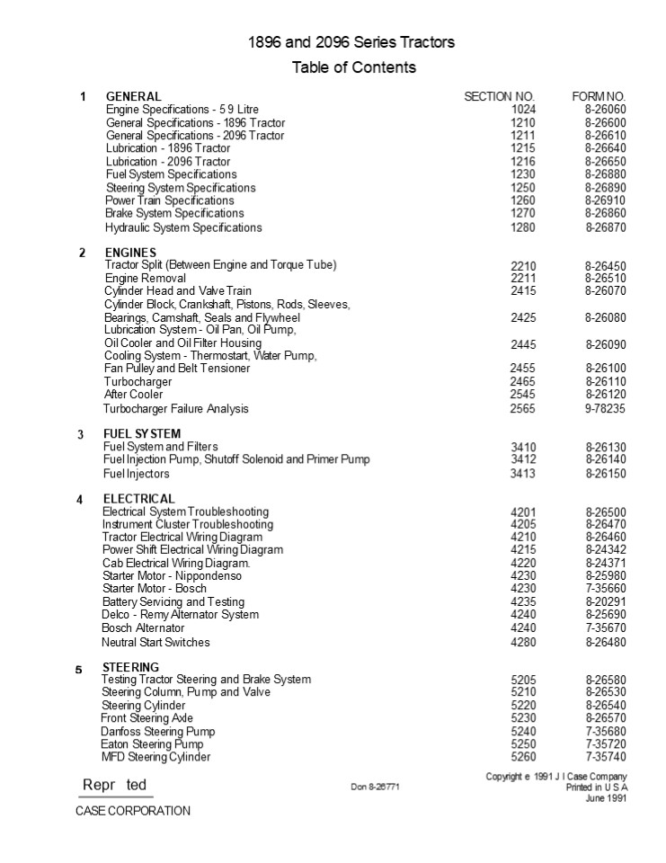
1896 and 2096 Series Tractors Table of Contents
1 GENERAL SECTION NO. FORM NO.
Engine Specifications - 5 9 Litre 1024 8-26060
General Specifications - 1896 Tractor 1210 8-26600
General Specifications - 2096 Tractor 1211 8-26610
Lubrication - 1896 Tractor 1215 8-26640
Lubrication - 2096 Tractor 1216 8-26650
Fuel System Specifications 1230 8-26880
Steering System Specifications 1250 8-26890
Power Train Specifications 1260 8-26910
Brake System Specifications 1270 8-26860
Hydraulic System Specifications 1280 8-26870
2 ENGINES Tractor Split (Between Engine and Torque Tube) 2210 8-26450
Engine Removal 2211 8-26510
Cylinder Head and Valve Train 2415 8-26070
Cylinder Block, Crankshaft, Pistons, Rods, Sleeves, Bearings, Camshaft, Seals and Flywheel 2425 8-26080
Lubrication System - Oil Pan, Oil Pump,
Oil Cooler and Oil Filter Housing Cooling System - Thermostart, Water Pump, 2445 8-26090
Fan Pulley and Belt Tensioner 2455 8-26100
Turbocharger 2465 8-26110
After Cooler 2545 8-26120
Turbocharger Failure Analysis 2565 9-78235
3 FUEL SYSTEM Fuel System and Filters 3410 8-26130
Fuel Injection Pump, Shutoff Solenoid and Primer Pump 3412 8-26140
Fuel Injectors 3413 8-26150
4 ELECTRICAL Electrical System Troubleshooting 4201 8-26500
Instrument Cluster Troubleshooting 4205 8-26470
Tractor Electrical Wiring Diagram 4210 8-26460
Power Shift Electrical Wiring Diagram 4215 8-24342
Cab Electrical Wiring Diagram. 4220 8-24371
Starter Motor - Nippondenso 4230 8-25980
Starter Motor - Bosch 4230 7-35660
Battery Servicing and Testing 4235 8-20291
Delco - Remy Alternator System 4240 8-25690
Bosch Alternator 4240 7-35670
Neutral Start Switches 4280 8-26480
STEERING Testing Tractor Steering and Brake System 5205 8-26580
Steering Column, Pump and Valve 5210 8-26530
Steering Cylinder 5220 8-26540
Front Steering Axle 5230 8-26570
Danfoss Steering Pump 5240 7-35680
Eaton Steering Pump 5250 7-35720
MFD Steering Cylinder 5260 7-35740
Copyright e 1991 J I Case Company Printed in U S
A June 1991
Repr ted
Don 8-26771
CASE CORPORATION
2
6 POWER TRAIN Troubleshooting Power Shift
Transmission Tractor Split (Between Torque and
Tube and Transmission) Torque Limiter
Clutch Hydraulic Pump Drive Power Shift Power
Shift Control Valve and Linkage Four Speed
Transmission Transfer Gearbox - MFD Tractors
Hydraulic PTO Rear Axles and Planetaries
Differential and Differential Lock Differential
and Drive Shaft - MFD Tractors Front Axle and
Planetaries - MFD Tractors Carraro MFD Axle
(715/20)
SECTION NO.
FORM NO.
6205 8-26780
6310 8-24501
6420 8-26490
6225 8-24820
6431 8-24491
6235 8-24660
6441 8-24521
6442 8-23441
6245 8-20410
6250 8-20420
6255 8-20430
6260 8-26710
6265 8-26720
6270 7-35130
7210 8-24670
7215 8-20531
7220 8-20540
7240 8-24470
7250 8-26560
8201 8-26760
8202 8-26590
8205 8-26630
8210 8-24570
8220 8-20591
8225 8-20601
8250 8-25371
8255 8-26690
8260 8-24690
8280 8-24610
8290 8-20640
9205 8-26680
9215 8-26700
9225 8-26730
9235 8-26740
9245 8-25580
9250 8-25511
9260 8-26660
9265 8-26670
9270 8-24511
9280 8-26750
9290 8-26520
- BRAKES
- Brakes Pressure Regulator Valve Park Lock System
- Brake Cylinders
- Brake Valve
- Park Hand Brake System
- HYDRAULIC
- Hydraulic Schematic Troubleshooting Hitch System
Testing Tractor Hydraulic System Hydraulic Oil
Filter - Hydraulic Charge Pump Hydraulic Pump
- Remote Hydraulic Valves
- Flow Divider and PTO Control Valve Differential
Lock Solenoid - Hitch System
- Break - Away Couplings and Portable Cylinders
- ACCESSORIES
- Troubleshooting - Air Conditioning System Gauging
and Testing Air Conditioning System - Compressor Isolation, Removal, Installation and
Evacuation Discharging, Evacuation and Charging
the Air Conditioning System Servicing Air
Conditioner Components - Servicing the Cab Blower
- Operator's Seat
- Hood, Grille and Side panel Removal and Alignment
Front End Removal - Cab Removal
14205 8-26550
16430 8-24731
18225 8-21350
Don 8-26771
Issued 6-91
Printed in U S A
3
Section
1024
SPECIFICATION DETAILS
Written In Clear And Simple English
IMPORTANT This engine was made using the metric
measurement system. All measurements and checks
must be made with metric tools to make sure of an
accurate reading when inspecting parts.
Printed in U.S.A. October, 1984
Rac 8-26060
CASE CORPORATION
4
https//www.ebooklibonline.com Hello dear
friend! Thank you very much for reading. Enter
the link into your browser. The full manual is
available for immediate download. https//www.ebo
oklibonline.com
5
1024-3
RUN-IN INSTRUCTIONS Engine Lubrication Fill the
engine crankcase with CD service classification
oil that has the correct viscosity rating for the
ambient air temperature. Install new oil filters,
after the engine has been rebuilt. Run-In
Procedure For Rebuilt Engine
Step 1
Disconnect the wire to the electric shut-off on
the injection pump so that the engine will not
start. Crank the engine for 30 seconds until
there is oil pressure, then reconnect the wire.
Step 2
Remove the air from the cooling system at the
temperature sending unit for the 1896 tractor.
Loosen the upper plug on the aftercooler to
remove the air from the cooling system for the
2096 tractor.
Step 3
Run the engine at 1000 RPM minimum load for 5
minutes and check for oil leaks.
Step 4 During the Run-In, continue to check the
oil pressure, coolant level, and coolant
temperature. Run-In Procedure For Rebuilt
Engines (With A Dynamometer) The following
procedure must be followed when using a PTO
dynamometer to Run-In the engine. The dynamometer
will control the engine load at each speed and
will remove stress on new parts during
Run-In. During the Run-In, continue to check the
oil pressure, coolant level and coolant
temperature.
STEP TIME ENGINE SPEED DYNAMOMETER SCALE LOAD
1 5 Minutes 1000 RPM 50
2 5 Minutes 1100 RPM 1/2
3 5 Minutes 2200 RPM Full
Run-In Procedure for Rebuilt Engines (Without A
Dynamometer)
STEP TIME ENGINE SPEED LOAD
1 5 Minutes 1000 RPM No Load
2 5 Minutes 1100 RPM Light Load
3 5 Minutes 2200 RPM Full
Run-In Procedure (Agriculture Tractors) For the
first 8 hours of field operation stay one gear
lower than normal. For the next 12 hours DO NOT
tug the engine. Prevent lugging by moving the
lever to a lower gear. The engine must not be
lugged below the rated engine RPM during early
hours of life. Run-In Procedure (Construction
Equipment) For the first 8 hours, operate the
engine at full throttle maintaining a normal
load. DO NOTbaby the engine, but avoid
converter or hydraulic stall. The engine must not
be lugged below the Rated Engine RPM (Do not
stall the engine more than 10 seconds).
Rac 8-26060
Issued 10-84
Printed in U.S.A.
6
1024-4
ENGINE SPECIFICATION DETAILS Cylinder
Block Metric Value Type .........................
..................................................
....... Non-SIeeved Material .....................
..................................................
............ Cast Iron ID of Cylinder
..................................................
................. 102.00 to 102.04 mm Maximum
Service Limit ....................................
............................ 102.116 mm Cylinder
Out of Round (Maximum) ...........................
.............................. 0.038 mm Cylinder
Taper (Maximum) .................................
............................... 0.076 mm 0.5 mm
Oversize Piston Machine Cylinder Bore to
..................................................
.... 102.50 to 102.54 mm 1.00 mm Oversize
Piston Machine Cylinder Bore to
................................ ......
.............. 103.00 to 103.04 mm Service
Cylinder Sleeve Type ............................
.............................................
Dry, Can Be Replaced Material ....................
..................................................
............. Cast Iron Machine Cylinder Block
Bore to ..........................................
..... 104.500 to 104.515 mm Installation
..................................................
.............................. Press Fit Machine
Sleeve Bore to Standard Size Piston
..................................................
........ 102.00 to 102.04 mm 0.5 mm Oversize
Piston ...........................................
............. 102.50 to 102.54 mm 1.0 mm Oversize
Piston ...........................................
............. 103.00 to 103.04 mm Piston Type
..................................................
................................ Cam
Ground Material ..................................
...........................................
Aluminum alloy OD at 12 mm From the Bottom, 90
Degrees From Piston Pin Standard Size Piston
..................................................
...... 101.873 to 101.887 mm Minimum Service
Limit ............................................
.................. 101.823 mm 0.5 mm Oversize
Piston ..........................................
........... 102.373 to 102.387 mm Minimum Service
Limit ............................................
.................. 102.323 mm 1.0 mm Oversize
Piston ..........................................
........... 102.873 to 102.887 mm Minimum Service
Limit ............................................
.................. 102.823 mm ID of Piston Pin
Bore .............................................
............... 40.006 to 40.012 mm Maximum
Service Limit ....................................
............................. 40.025 mm Width of
1st Ring Groove (Top) ...........................
......................... 2.465 to 2.485 mm Width
of 2nd Ring Groove (Intermediate)
........................................... 2.425
to 2.445 mm Width of 3rd Ring Groove (Oil Ring)
................................................
4.040 to 4.060 mm Protrusion Above Cylinder Block
(Maximum) .......................................
........ 0.660 mm Piston Pin Type
..................................................
.................................... Full
Float OD of Pin ..................................
..................................... 39.997 to
40.003 mm Minimum Service Limit
..................................................
............... 39.990 mm
Rac 8-26060
Issued 10-84
Printed in U.S.A.
7
2210-2 TABLE OF CONTENTS SPECIAL
TORQUES ..........................................
.................................... 2 SPECIAL
TOOLS ...........................................
...................................... 3 TRACTOR
SPLIT Disassembly ................................
.................................................
4-12 Disconnects On LH Side Of Tractor
..................................................
........ 7-9 Disconnects On RH Side Of Tractor
..................................................
......... 10 Installing The Front And Rear Split
Stands ..........................................
........ 11,12 Assembly .........................
..................................................
........ 13-20
SPECIAL TORQUES U.S. Value Engine Flywheel
Housing To Torque Tube Mounting Bolts . 149 to
179 lb ft
Metric Value 202 to 243 Nm (20.2 to 24.3 kgm)
366 to 439 Nm (36.6 to 43.9 kgm)
Drawbar Support And Pivot Bracket Mounting Bolts
....... 270 to 324 lb ft
91 to 107 Nm (9.1 to 10.7 kgm)
Starter Ground Bolt .............................
........... 67 to 79 lb ft
50 to 66 Nm (5.0 to 6.6 kgm)
MFD Drive Shaft Mounting Bolts ...................
......... 37 to 49 Ib ft
Issued 1-85
Printed in U.S.A.
Rac 8-26450
8
2210-3
SPECIAL TOOLS
504 GASKET ELIMINATOR - B17428 50 ml TUBE B17504
300 ml CARTRIDGE
LB FT TOROUE WRENCH
CAS-10102-1 ADAPTER FOR REAR STAND
CAS-10749 FRONT SPLIT STANDS
FRONT SUPPORT BRACKET NOTE PART OF
CAS-10100A TRACTOR SPLIT STAND KIT.
CAS-10102A REAR SPLIT STAND
Issued 1-85
Printed in U.S.A.
Rac 8-26450
9
2210-4
TRACTOR SPLIT Disassembly TEP 4
STEP 1
Put the gear shift control lever in the PARK
posi- tion.
Remove the starter ground bolt to disconnect the
battery negative cable and the cab ground cable.
STEP 2
STEP
APPLY TAPE
Pull the hand brake, if equipped, fully up to
engage the park brake.
Put electrical tape around the eye terminal on
the end of the battery negative cable.
IMPORTANT Be sure to use enough tape to give
insulation against contact with the positive
battery cables.
STEP 3
Put blocks in front of and behind the tractor
tires.
Rac 8-26450
Issued 1-85
Printed in U.S A
10
2210-5
STEP
STEP 9
Remove the nut on the starter solenoid terminal
for the battery positive cable. Remove the
battery pos- itive cable.
Remove the lock pin from the drawbar pivot pin.
STEP 1
TEP 7
REMOVE BATTERIES,
Remove the pivot pin from the drawbar.
CABLES AND BOX Remove the batteries, battery box
and cables.
TEP 11
STEP 8
Pull the drawbar toward the rear of the tractor.
Put a container under the transmission housing.
Re- move the drain plug and drain the oil.
Remove the battery box support plate.
Rac 8-26450
Issued 1-85
Printed in U.S.A.
11
2210-6
STEP 12
STEP 15
Put a container under the transfer gear box. Re-
move the drain plug and drain the oil.
Put a container under the engine flywheel
housing. Remove the drain plug and drain the oil.
NOTE On tractors without a transfer gear box,
remove the drain plug from the torque tube hous-
ing and drain the oil. STEP 13 MFD ONLY
Remove the mounting bolts on each end of the MFD
drive shaft. STEP 14 MFD ONLY
Push the front yoke forward and lower the drive
shaft to the floor.
Rac 8-26450
Issued 1-85
Printed in U S.A
12
2210-7
DISCONNECTS ON LH SIDE OF TRACTOR
STEP 16
STEP 19
DISCONNECT
Disconnect the instrument cluster cable from the
true ground speed sensor, if equipped.
Disconnect the self sealing couplers on the air
conditioning receiver-drier to cab pressure tube.
STEP 20
STEP 17
W APPLY TAPE
Put tape on the end of the cable and over the
connector on the sensor.
Remove the cotter pin from the throttle cable
pivot pin.
STEP 21
STEP 18
DISCONNECT
DISCONNECT
Disconnect the self sealing couplers on the air
conditioning compressor to cab suction tube.
Disconnect the throttle cable from the bracket.
Rac 8-26450
Issued 1-85
Printed in U.S.A.
13
2210-8
STEP 25
STEP 22
DISCONNECT
Close the fuel shutoff valve on the lift fuel
pump.
Disconnect the fuel return tube from the fitting.
STEP 23
STEP 26
CLOSE VALVE
Disconnect the fuel supply tube from the shutoff
valve.
Close the valve in the cylinder head for the cab
heater outlet hose. Disconnect the hose from the
valve.
STEP 27
Remove the fuel supply tube and connect the tube
to a closed shutoff valve.
Put identification tags on each front steering
pump tube so that the tubes can be correctly
installed later. Remove the four tubes from the
pump. Put caps in the tubes and on the pump
fittings.
Rac 8-26450
Issued 1-85
Printed in U S.A.
14
2210-9
STEP 28
STEP 31
DISCONNECT
Disconnect the lower front flood lamp harness (if
equipped) from the engine harness.
Fasten the throttle cable, the two air
conditioning lines and the two fuel lines to the
cab.
STEP 29
Loosen the engine harness mounting bolt from the
connector on the front of the cab. STEP 30
Disconnect the engine harness from the lower
cab harness.
Rac 8-26450
Issued 1-85
Printed in U.S.A.
15
2210-10
DISCONNECTS ON RH SIDE OF TRACTOR
STEP 32
STEP 35
LOOSEN
Disconnect the cab heater core inlet hose from
the valve.
Loosen the pyrometer at the turbocharger exhaust
elbow.
STEP 33
STEP 36
DISCONNECT
. Remove the pyrometer.
Disconnect the neutral start switch intermediate
wire from the ignition solenoid wire.
STEP 34
CLOSE VALVE Close the valve on the water inlet
housing.
Rac 8-26450
Issued 1-85
Printed in U.S.A.
16
2210-11
INSTALLING THE FRONT AND REAR SPLIT STANDS
STEP 37
STEP 39
FRONT SUPPO RT BRACKET
Remove the mounting bolts from the drawbar sup-
port and pivot bracket.
InstalI the rear split stand under the
transmission housing. See the Special Tools page.
NOTE The two holes in the front support bracket
of the rear sp//f stand must a//gn with the two
front holes in the transmission housing for the
drawbar support and pivot bracket.
STEP 38
STEP 40
CO NTACT POINT
Remove the bracket from the transmission hous-
ing.
REAR STAND ADAPTER
The rear stand adapter must support the transmis-
sion housing on the inside of the hitch sensing
springs.
Rac 826450
Issued 1-85
Printed in U.S.A
17
2210-12 STEP 41
USE THESE HOLES
REAR H LF
ONT HALF
Use the four holes in each side rail to install
the front split stands.
Push the front half of the tractor away from the
rear half of the tractor.
STEP 42
TOP LEG TOWARD FRONT OF TRACTOR
Install the front split stands to the side rails.
The top leg of each stand must be toward the
front of the tractor. Install the bolts through
the stands and through the side rails. Install
the nuts on the inside of the side rails. See the
Special Tools page.
REAR HALF OF TRACTOR
PLANETARY INPUT DRIVE SHAFT
STEP 4
PTO DRIVE SHAFT
Continue to separate the tractor halves until the
PTO drive shaft and the planetary input drive
shaft are removed from the engine flywheel and
torque limiter plates.
Remove the mounting bolts that retain the engine
flywheel housing to the torque tube.
Issued 1-85
Printed in U.S.A.
Rac 8-26450
18
2210-13
Assembly
TEP
EP 48
TOROUE TUBE FLANGE
Install two pilot studs (14 mm x 2.0) into the
torque tube. STEP 49
ENGINE FLYWHEEL HOUSING FLANGE
Clean the mounting flanges of the engine flywheel
housing and torque tube of all foreign material.
REAR HALF FRONT HALF Push the front half of the
tractor towards the rear half of the tractor.
Rotate the engine flywheel to align the PTO drive
shaft splines with the torque limiter plate
splines. Continue to push the tractor halves
together until the mounting surfaces make contact.
ST
Apply Loctite 504 Gasket Eliminator to the mount-
ing flange of the torque tube. Apply the gasket
eliminator around each hole and down the center
of the mounting flange. See the Special Tools
page. NOTE Use Loctite Safety Solvent to clean
the surface before using Loctite 504.
Rac 8-26450
Issued 1-85
Printed in U.S.A.
19
Suggest If the above button click is invalid.
Please download this document first, and then
click the above link to download the complete
manual. Thank you so much for reading
20
2210-14
STEP 53
STEP 50
CONNECT
Connect the neutral start switch intermediate
wire to the ignition solenoid wire.
Remove the pilot studs. Install the torque tube
to engine flywheel housing mounting bolts and
lock washers. Tighten the bolts to a torque of
149 to 179 lb ft (202 to 243 Nm)(20.2 to 24.3
kgm).
STEP 54
STEP 51
Connect the cab heater core inlet hose to the
shu- toff valve on the water inlet housing.
REMOVE STANDS Remove the front split stands.
STEP 55
STEP 52
OPEN VALVE
REMOVE STAND
Open the valve on the water inlet housing.
Remove the rear split stand.
Issued 1-85
Printed in U.S.A.
Rae 8-26450
21
https//www.ebooklibonline.com Hello dear
friend! Thank you very much for reading. Enter
the link into your browser. The full manual is
available for immediate download. https//www.ebo
oklibonline.com
Recommended
