
New Holland T4030 Tractor Service Repair Manual Instant Download PowerPoint PPT Presentation
Title: New Holland T4030 Tractor Service Repair Manual Instant Download
1
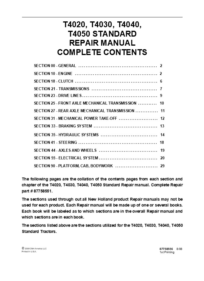
T4020, T4030, T4040, T4050 STANDARD REPAIR
MANUAL COMPLETE CONTENTS
SECTION 00 - GENERAL .............................
............... 2 SECTION 10 - ENGINE
..............................................
2 SECTION 18 - CLUTCH ............................
.................. 6 SECTION 21 - TRANSMISSIONS
..................................... 7 SECTION
23 - DRIVE LINES .................................
......... 9 SECTION 25 - FRONT AXLE MECHANICAL
TRANSMISSION ........... 10 SECTION 27 - REAR
AXLE MECHANICAL TRANSMISSION ............. 11
SECTION 31 - MECHANICAL POWER TAKE-OFF
...................... 12 SECTION 33 - BRAKING
SYSTEM ....................................
13 SECTION 35 - HYDRAULIC SYSTEMS
................................ 14 SECTION 41 -
STEERING .........................................
... 18 SECTION 44 - AXLES AND WHEELS
................................. 19 SECTION 55 -
ELECTRICAL SYSTEM ................................
. 20 SECTION 90 - PLATFORM, CAB, BODYWORK
........................ 29 The following pages
are the collation of the contents pages from each
section and chapter of the T4020, T4030, T4040,
T4050 Standard Repair manual. Complete Repair
part 87758551. The sections used through out
all New Holland product Repair manuals may not be
used for each product. Each Repair manual will
be made up of one or several books. Each book
will be labeled as to which sections are in the
overall Repair manual and which sections are in
each book. The sections listed above are the
sections utilized for the T4020, T4030, T4040,
T4050 Standard Tractors.
? 2008 CNH America LLC Printed In U.S.A.
87758556 8/08 1st Printing
2
SECTION 00 - GENERAL - CHAPTER 1
1
SECTION 00 - GENERAL Chapter 1 -
General CONTENTS
Description Page General Instructions
..................................................
.......... 3 Health and Safety
..................................................
............ 5 Precautionary Statements
..................................................
... 15 Safety ....................................
.................................. 16 Ecology and
the Environment ..................................
................ 19 Minimum Hardware Tightening
Torques .........................................
20 Federal Emissions Warranty ....................
............................... 22 California
Emission Control Warranty Statement
.................................. 23
Consumables ......................................
.......................... 25
Section
3
SECTION 00 - GENERAL - CHAPTER 1 WARNING WARNING
2
All maintenance and repair work described in
this manual must be performed exclusively by New
Holland service technicians in strict accordance
with the instructions given and using any
specific tools necessary.
The Manufacturer and all organizations belong-
ing to the Manufacturers distribution network,
including but not restricted to national,
regional or local distributors, will accept no
responsibility for personal injury or damage to
property caused by abnormal function of parts
and/or compo- nents not approved by the
Manufacturer, including those used for
maintenance and/or repair of the product
manufactured or marketed by the Manufacturer. In
any case, the product manufactured or marketed
by the Manufacturer is covered by no guarantee
of any kind against personal injury or damage to
property caused by abnormal function of parts
and/or components not approved by the
Manufacturer.
WARNING
Anyone who performs the operations described
herein without strictly following the
instructions is personally responsible for
resulting injury or damage to property.
4
https//www.ebooklibonline.com Hello dear
friend! Thank you very much for reading. Enter
the link into your browser. The full manual is
available for immediate download. https//www.eb
ooklibonline.com
5
SECTION 00 - GENERAL - CHAPTER 1
3
GENERAL INSTRUCTIONS
IMPORTANT NOTICE All maintenance and repair
operations described in this manual should be
carried out exclusively by the authorized
workshops. All instructions detailed should be
carefully observed and special equipment
indicated should be used if necessary. Everyone
who carries out service operations described
without carefully observing these direc- tives
will be directly responsible for resulting
consequences.
- Take care to insert the seal perpendicular to its
seat while you are pressing it. Once the seal is
settled, ensure that it contacts the thrust
element, if required - To prevent damaging the sealing lip against the
shaft, place a suitable protection during
installation.
O RINGS Lubricate the O rings before inserting
them into their seats. This will prevent the O
rings from roll over and twisting during
mounting, which will jeopardize sealing.
SHIMMING At each adjustment, select adjusting
shims, measure them individually using a
micrometer and then sum up recorded values. Do
not rely on measuring the whole shimming set,
which may be incorrect, or on the rated value
indicated for each shim.
SEALERS Apply silicone/gasket eliminator over the
mating surfaces marked with an X. Before
applying the sealer, prepare the surface as
follows
ROTATING SHAFT SEALS To correctly install
rotating shaft seals, observe the following
instructions
- remove possible scales using a metal brush
- thoroughly degrease the surfaces using one of
the following cleaning agents trichlorethylene,
diesel fuel or a water and soda solution.
- Let the seal soak into the same oil as it will
seal for at least half an hour before mounting - Thoroughly clean the shaft and ensure that the
shaft working surface is not damaged - Place the sealing lip towards the fluid. In case
of a hydrodynamic lip, consider the shaft
rotation direction and orient grooves in order
that they deviate the fluid towards the inner
side of the seal - Coat the sealing lip with a thin layer of
lubricant (oil rather than grease) and fill the
gap between the sealing lip and the dust lip of
double lip seals with grease - Insert the seal into its seat and press it down
using a flat punch. Do not tap the seal with a
hammer or a drift
BEARINGS It is advisable to heat the bearings to
80? to 90?C (176? to 194?F) before mounting them
on their shafts and cool them down before
inserting them into their seats with external
tapping.
SPRING PINS When mounting split socket spring
pins, ensure that the pin notch is oriented in
the direction of the effort to stress the
pin. Spiral spring pins should not be oriented
during installation.
6
SECTION 00 - GENERAL - CHAPTER 1
4
- GENERAL INSTRUCTIONS
- PRECAUTIONARY NOTICE
- Only authorized workshops should carry out
maintenance and repair operations on the tractor,
or tractor compo- nents. Carefully observe all
instructions, safety precautions, and the use of
equipment such as special tools, as detailed in
this manual. Damage to the tractor, or injury to
personnel is the direct responsibility of anyone
who fails to observe these precautions. - EQUIPMENT NOTICE
- The equipment proposed in this manual is
- Designed and studied expressly for use on Case IH
tractors - Necessary for adequate and reliable repair of the
tractor - Strictly tested for the efficient and long
lasting life cycle of the tractor - SPARE PARTS NOTICE
- Genuine New Holland spare parts guarantee the
same quality, safety and life cycle as original
components. These parts bear the logo. - GENERAL NOTICES
- In this manual, the description FRONT, REAR,
RIGHT- HAND and LEFT- HAND refer to the view
seen by the operator while in the operators
seat, looking in the direction in which the
tractor normally moves. - Wear limits detailed in this manual, although
advised, are not binding.
7
SAFETY
SECTION 00 - GENERAL - CHAPTER 1
16
PRECAUTIONARY STATEMENTS A careful operator is
the best operator. Most accidents can be avoided
by observing certain precautions. To help
prevent accidents, read the following precautions
before operating this equipment. Equipment should
be operated only by those who are responsible
and instructed to do so. Carefully review the
procedures given in this manual with all
operators. It is important that all operators be
familiar with and follow safety precautions.
THE TRACTOR
- on public roads. Brake both wheels simulta-
neously when making an emergency stop. - Use extreme caution and avoid hard application
of the tractor brakes when towing heavy loads at
road speeds. - Any towed vehicle whose total weight exceeds
that of the towing tractor must be equipped with
brakes for safe operation. - Never apply the differential lock when turning.
When engaged, the differential lock will prevent
the tractor from turning. - Always check overhead clearance, specifically
when transporting the tractor. Watch where you
are going, especially at low overhanging
obstacles. - Use extreme caution when operating on steep
slopes.
- Read the Operators Manual carefully before
using the tractor. Lack of operating knowledge
can lead to accidents. - Only allow properly trained and qualified persons
to operate the tractor. - To prevent falls, use the handrails and step
plates when getting on and off the tractor. Keep
steps and platform clear of mud and debris. - Do not permit anyone but the operator to ride on
the tractor unless a passenger seat is fitted.
There is no safe place for extra riders
otherwise. - Replace all missing, illegible or damaged safety
decals. - Keep safety decals free of dirt or grime.
- Do not modify or alter or permit anyone else to
modify or alter the tractor or any of its
components or any tractor function without first
consulting your dealer. - Tractor wheels are very heavy. Handle with care
and ensure, when stored, that they cannot fall.
- To avoid overturns, drive the tractor with care
and at speeds compatible with safety, especially
when operating over rough ground, when crossing
ditches or slopes and when turning. - If the tractor becomes stuck or the tires are
frozen to the ground, reverse the tractor out to
prevent corners. - Keep the tractor in the same gear when going
downhill as would be used when going uphill. Do
not coast or freewheel down hills. - OPERATING THE TRACTOR
- Apply the parking brake, place the PTO control in
the OFF position, the lift control lever in
the down position, the remote control valve
levers in the neutral position and the
transmission lever in neutral before starting
the tractor. - Do not start the engine or operate controls while
standing beside the tractor. Always sit in the
tractor seat when starting the engine or
operating the controls.
DRIVING THE TRACTOR
- Always sit in the drivers seat while starting or
driving the tractor. - When driving on public roads, have considera-
tion for other road users. Pull off the road
occasionally to allow any following traffic to
pass. Do not exceed the legal speed limit set in
your area. - Use low beam lights when meeting a vehicle at
night. Make sure the lights are adjusted to
prevent blinding the driver of an oncoming
vehicle - Reduce speed before turning or applying the
brakes. Ensure that both brake pedals are locked
together when traveling at road speeds or when
8
SECTION 00 - GENERAL - CHAPTER 1
17
- Do not bypass the neutral start switches. Consult
your authorized dealer if your neutral start
controls malfunction. Use jump cables only in the
recommended manner. Improper use can result in
a tractor runaway. - Avoid accidental contact with the gear shift
levers while the engine is running. Unexpected
tractor movement can result from such contact. - Do not get off the tractor while it is in motion.
- Shut off the engine and PTO and apply the
parking brake before getting off the tractor. - Do not park the tractor on a steep incline.
- Do not run the tractor engine in an enclosed
building without adequate ventilation. Exhaust
fumes are toxic and can cause death. - Always wear a protective mask when working with
toxic spray chemicals. Follow the directions on
the chemical container.
a hazard both to the operator and to bystanders.
Do not overload or operate with attached
equipment which is unsafe, not designed for the
particular task or is poorly maintained. 19. The
tractor is designed to provide the minimum noise
level at the operators ears and meets or
exceeds applicable standards in this respect.
However, noise (sound pressure level) in the
workplace can exceed 86 dB(A) when working
between buildings or in confined spaces.
Therefore, it is recommended that operators wear
suitable ear protectors during vehicle
operation. OPERATING THE PTO
- When operating PTO driven equipment, shut off
the engine and wait until the PTO stops before
getting off the tractor and disconnecting the
equipment. - Do not wear loose clothing when operating the
power take-off or especially when near rotating
equipment. - When operating stationary PTO driven equip-
ment, always apply the tractor parking brake and
block the rear wheels front and back. - To avoid injury, do not clean, adjust, unclog or
service PTO driven equipment when the tractor
engine is running. - Make sure the PTO guard is in position at all
times and always replace the PTO cap when the
PTO is not in use.
- If the power steering or engine ceases operating,
stop the tractor immediately as the tractor will
be more difficult to control. - Stop the engine and relieve pressure before
connecting or disconnecting hydraulic, steering
or fuel lines. - Tighten all connections before starting the
engine or pressurizing lines. - Pull only from the swinging drawbar or the lower
link drawbar in the lowered position . Use only a
drawbar pin that locks in place. Pulling from
the tractor rear axle or any point above the
axle may cause the tractor to overturn. - If the front end of the tractor tends to rise
when heavy implements are attached to the three-
point hitch, install front end or front wheel
weights. Do not operate the tractor with a light
front end. - Always select Position Control when attaching
implements and when transporting equipment. Be
sure hydraulic couplers are properly installed
and will disconnect safely in case of accidental
detachment of the implement. - Do not leave equipment in the raised position
when the vehicle is stopped or unattended. - Ensure any attached equipment or accessories are
correctly installed, are approved for use with
the tractor, do not overload the tractor and are
operated and maintained in accordance with the
instructions issued by the equipment or
accessory manufacturer. - Remember that your tractor, if abused or
incorrectly used, can be dangerous and become
SERVICING THE TRACTOR
- The cooling system operates under pressure which
is controlled by the radiator cap. It is
dangerous to remove the cap while the system is
hot. Always turn the cap slowly to the first stop
and allow the pressure to escape before
removing the cap entirely. - Do not smoke while refueling the tractor. Keep
any type of open flame away. Wait for the engine
to cool before refueling. - Keep the tractor and equipment, particularly
brakes and steering, maintained in a reliable and
satisfactory condition to ensure your safety and
comply with legal requirements. - To prevent fire or explosion, keep open flames
away from battery or cold weather starting aids.
To prevent sparks which could cause explosion,
use jumper cables according to instructions. - Stop the engine before performing any service on
the tractor.
9
SECTION 00 - GENERAL - CHAPTER 1
18
- Escaping diesel/hydraulic fluid under pressure
can penetrate the skin causing serious injury. - Do not use your hand to check for leaks. Use a
piece of cardboard or paper to search for leaks. - Stop the engine and relieve pressure before
connecting or disconnecting lines. - Tighten all connections before starting the
engine. - If fluid is injected into the skin obtain medical
attention immediately. - Do not modify or alter or permit anyone else to
modify or alter the tractor or any of its
components or any tractor function without first
consulting an authorized dealer. - The fuel oil in the injection system is under
high pressure and can penetrate the skin.
Unqualified persons should not remove or attempt
to adjust a pump, injector, nozzle or any other
part of the injection system. Failure to follow
these instructions can result in serious injury. - Continuous long term contact with used engine
oil my cause skin cancer. Avoid prolonged
contact with used engine oil. Wash skin promptly
with soap and water.
- Do not fill the fuel tank to capacity. Allow room
for expansion. - Wipe up spilled fuel immediately.
- Always tighten the fuel tank cap securely.
- If the original fuel tank cap is lost, replace it
with an approved cap. A non-approved cap may not
be safe. - Keep equipment clean and properly maintained.
- Do not drive equipment near open fires.
- Never use fuel for cleaning purposes.
- Arrange fuel purchases so that summer grade
fuels are not used in the winter. - ROPS
- The tractor may be equipped with a safety frame
(ROPS) which must be maintained in a serviceable
condition. Be careful when driving through
doorways or working in confined spaces with low
headroom.
- Do not modify, drill, weld or alter the ROPS in
any way. - Never attempt to straighten or weld the ROPS or
retaining brackets, which have suffered damage.
By doing so you may weaken the structure and
endanger your safety. - Do not secure any parts on the ROPS or attach it
with other than the special high tension bolts
and nuts specified. - Never attach chains or ropes to the safety frame
or roll bar for pulling purposes. - Never take unnecessary risks even though your
safety frame or roll bar affords you the maximum
protection possible. - Whenever possible, operate with the ROPS in its
fully upright and locked position.
DIESEL FUEL
- Under no circumstances should gasoline, alcohol
or blended fuels be added to diesel fuel. These
combinations can create an increased fire or
explosive hazard. In a closed container such as
a fuel tank these blends are more explosive than
pure gasoline. Do not use these blends. - Never remove the fuel cap or refuel with the
engine running or hot. - Do not smoke while refueling the tractor or when
standing near fuel. Keep any type of open flame
away. Wait for the engine to cool before
refueling. - Maintain control of the fuel filter pipe nozzle
when filling the tank.
10
SECTION 10 - ENGINE - CHAPTER 1
1
SECTION 10 - ENGINE Chapter 1 - Engine CONTENT
Description Page Specifications
..................................................
................ 4 Torques .......................
..............................................
12 Special Tools .................................
............................... 14 Sectional
Views ............................................
.................. 15 Exhaust Gas Recirculation
System (EGR) ....................................
19 Troubleshooting ..............................
................................ 20 Engine
..................................................
................ 24 Removal ......................
.......................................
24 Installation ..................................
.......................... 31 Disassembly
..................................................
........ 33 Removing the Crankshaft Front Seal
..................................... 35 Removing
the Crankshaft Rear Seal .........................
............ 38 Assembly on the Bench
..................................................
.. 44 Fitting the Bushings .......................
............................. 44 Fitting the
Tappets ..........................................
........... 45 Fitting the Camshaft
..................................................
. 45 Fitting the Oil Nozzles .....................
............................. 46 Fitting the
Crankshaft .......................................
........... 46 Fitting the Connecting Rod- piston
Assembly .............................. 49
Fitting the Piston Connecting Rod Assemblies In
the Cylinder Liners .......... 50 Big End Cap
Assembly .........................................
........... 51 Fitting the Thermostat Valve
............................................
52 Fitting the Cylinder Head .....................
.......................... 52 Fitting the
Injectors ........................................
............ 54 Fitting the Rocker Arm Assembly
........................................
54 Fitting the Timing Gear .......................
.......................... 55 Fitting the
Injection Pump ...................................
............ 57 Fitting the Additional
Counterweights ...................................
.. 57 Fitting the Hydraulic Pump Drive Gear
.................................... 58 Fitting
the Timing Gear Casing ...........................
............... 59 Fitting the Crankshaft Rear
Seal .........................................
59 Fitting the Flywheel ..........................
.......................... 59
Section
10 001 10
10 001 54
11
2
SECTION 10 - ENGINE - CHAPTER 1
Description Page Fitting the Oil Pump
..................................................
.. 60 Fitting the Oil Sump .......................
............................. 61 Fitting the
Crankshaft Front Seal ............................
............. 61 Fitting the Crankshaft Front
Pulley .......................................
61 Fitting the Cooling System Union
........................................
61 Fitting the Coolant Pump ......................
......................... 62 Fitting the Fan-
Alternator Pulley ................................
......... 62 Fitting the Auxiliary Member Drive
Belt ...................................
64 Fitting the Exhaust Manifold - Turbine
.................................... 64 Fitting
the Injector Feed Pipes ..........................
................. 64 Fitting the Fuel Pump - Feed
Pipes ...................................... 65
Fitting the Pipes Between the Fuel Supply and
Injection Pumps, Pre-Heating System and Tappet
Cover ...................................
65 Fitting the Starter Motor .....................
........................... 66 Checks,
Measurements and Repairs .........................
................... 67 Crankcase, Cylinder Liners
.................................................
67 Crankshaft ....................................
........................... 70 Connecting Rods
..................................................
....... 72 Bushings ..............................
............................... 72 Checking
Connecting Rods ..................................
........... 73 Checking Twisting
..................................................
... 73 Checking Bending ..........................
........................... 73 Pistons
..................................................
................ 74 Measuring the Piston Diameter
..........................................
75 Piston Pins ...................................
........................ 75 Conditions For
Correct Pin-piston Coupling ......................
......... 76 Piston Rings .......................
................................... 76 Measuring
the Clearance X of the V-ring ....................
.............. 77 Valves and Camshaft
..................................................
.... 78 Decarbonizing, Checking and Grinding
Valves ............................. 78 Valve
Springs ..........................................
............... 80 Tappets .......................
.......................................
80 Camshaft ......................................
....................... 81 Checking Cam Lift and
Pin Alignment ....................................
81 Cylinder Head ...............................
............................. 82 Cylinder Head
Thickness ........................................
....... 82 Cylinder Head Hydraulic Seal Check
..................................... 82
Section
12
SECTION 10 - ENGINE - CHAPTER 1
3
Description Page Low Oil Pressure Indicator
.................................................
83 Functional Checks .............................
........................ 83 Oil Filter
Replacement ......................................
............... 83 Cooling System
..................................................
......... 84 Radiator - Flushing and Checks
.........................................
84 Coolant Thermometer - Check ...................
....................... 84 Thermostat Valve -
Replacement ......................................
.. 84 Crankshaft Front Seal ......................
............................... 85 Replacement
..................................................
....... 85 Crankshaft Rear Seal
..................................................
... 87 Removal ...................................
.......................... 87 Installation
..................................................
.......... 88 Adjusting Valve/Rocker Arm
Clearance ......................................
90 Adjustment ...................................
........................ 90 Injectors
..................................................
............... 93 Removal .......................
......................................
93 Installation ..................................
.......................... 95 Bosch Injection
Pump .............................................
........ 96 Removal ..............................
............................... 96 Installation
..................................................
.......... 97 Timing .............................
.................................. 99 Fuel
Circuit Air Bleeding .............................
.................. 101 Coolant Pump
..................................................
......... 102 Removal ............................
................................ 102 Installation
..................................................
......... 103 Thermostatic Valve
..................................................
..... 104 Removal ................................
............................ 104 Installation
..................................................
......... 105 Radiator ...........................
..................................... 106 Removal
..................................................
.......... 106 Installation ......................
.....................................
109 4-Cylinder Coolant Pump and Generator Drive
Belt ........................... 110 Tension
adjustment .......................................
............ 110
Section
10 102 70
10 102 74
10 106 12
10 218 30
10 246 14
10 402 10
10 402 30
10 406 10
10 414 10
13
4
SECTION 10 - ENGINE - CHAPTER 1
SPECIFICATIONS
GENERAL SPECIFICATIONS GENERAL SPECIFICATIONS
Engine, technical type
- Model T4040 type F4CE9484NJ601 (BOSCH pump) ....
- Model T4050 - type F4CE9484MJ601 (BOSCH pump) . .
Cycle ................................................. diesel, 4- stroke
Fuel injection .......................................... Direct
Number of cylinders in line ............................... 4
Piston diameter ............................. mm (inch) 104 (4.09)
Piston stroke ........................................... 132 (5.20)
Total displacement ........................... mm (inch) 4485 cm3 (1766 cu/inch)
Compression ratio ...................................... 16.51
Maximum Power Output
- Model T4040 - type F4CE9484NJ601 ................. 63 kW (86 Hp)
- Model T4050 - type F4CE0454CD600/D603 .......... 71 kW (97 Hp)
Maximum power speed .................................. 2300 rpm
- Maximum torque Model T4040 - type F4CE9484NJ601 . 370 Nm (273 ft-lb)
- Maximum torque Model T4050 - type F4CE9484MJ601 . 418 Nm (308 ft-lb)
Maximum torque speed ................................. 1300 rpm
Number of main bearings ................................ 5
Sump pan ............................................. structural, cast iron
Lube ................................................. Pump drive ............................................ Engine speed/oil pump speed ratio ........................ Oil filtration ............................................ forced, with lobe pump from crankshaft 11 mesh screen on oil pick- up and filter cartridge in delivery line
Normal oil pressure with motor warmed- up at slow idling ........................................... 1.2 bar (17.40 psi)
at fast idling ............................................ 3.9 bar (56.56 psi)
(continued)
14
SECTION 10 - ENGINE - CHAPTER 1
15
SECTIONAL VIEWS
MIF1096A
1
Engine view
15
16
SECTION 10 - ENGINE - CHAPTER 1
Oil
path under pressure Oil return path under
gravity MIF1098A
2
Engine lubrication diagram
Forced- circulation lubrication is accomplished
by the following components
- oil pressure control valve incorporated in the
cooler assembly - by- pass valve to cut off clogged oil filter,
incorporated in the cooler assembly - cartridge oil filter.
- oil pump, housed at the front of the crankcase,
driven by the grooved bushing keyed onto the
shank of the crankshaft - water / oil cooler, housed in the crankcase
16
SECTION 10 - ENGINE - CHAPTER 1
17
Coolant
recirculating in the engine Coolant entering the
pump MIF1099A
3
Cooling diagram
The forced circulation, closed- circuit engine
cooling system is composed of the following
components - a lubricating oil cooler
- a centrifugal coolant pump housed at the front of
the crankcase - a thermostat valve governing coolant circulation.
17
18
SECTION 10 - ENGINE - CHAPTER 1
MIF1102A
4
Additional counterweight diagram
- Retaining bolts
- Support
- Retaining bolts
- Gear
- Balancing weight
- Half bearings
- Counter- shaft
- Gear
- Ring
10. O- rings
18
Suggest If the above button click is invalid.
Please download this document first, and then
click the above link to download the complete
manual. Thank you so much for reading
19
SECTION 10 - ENGINE - CHAPTER 1
19
5
Camshaft view B. Exhaust valve cam.
A. Inlet valve cam.
EXHAUST GAS RECIRCULATION SYSTEM (EGR) On the
TIER 3 version, the exhaust cam profile has been
modified to permit partial opening of the related
valve during the inlet phase (exhaust gas
recirculation EGR) with the consequent re-
introduction of some of the exhaust gases into
the engine cylinders. The exhaust gases can be
partially redirected into the cylinders in order
to reduce the maximum combustion temperature
values which are responsible for the production
of nitrogen oxide (NOx). The exhaust gas
recirculation system (EGR), reducing the
temperature of combustion by decreasing the
concentration of oxygen in the combustion
chamber, is therefore an effective system to
control emissions of NOx.
The internal EGR system is not provided with any
electronically controlled elements the system is
always on.
Its configuration needs no additional elements
such as control valves, pipes or heat exchangers.
The exhaust cam (B) in addition to the main lobe
has another lobe (see sect. A- A, fig. 5) with
respect to the configuration without EGR.
The additional lobe, during the inlet phase of
the cylinder under examination, permits briefly
opening the exhaust valve generating
recirculation due to the exhaust gases returning
caused by the lower pressure created in the
inlet phase inside the cylinder.
20
https//www.ebooklibonline.com Hello dear
friend! Thank you very much for reading. Enter
the link into your browser. The full manual is
available for immediate download. https//www.eb
ooklibonline.com
Recommended
