

VOLVO EC210 NLC EC210NLC EXCAVATOR Service Repair Manual Instant Download PowerPoint PPT Presentation
Title: VOLVO EC210 NLC EC210NLC EXCAVATOR Service Repair Manual Instant Download
1
Service Information
Document Title Track gearbox, removal Function Group 4311 Information Type Service Information Date 2015/11/3
Profile Profile Profile Profile
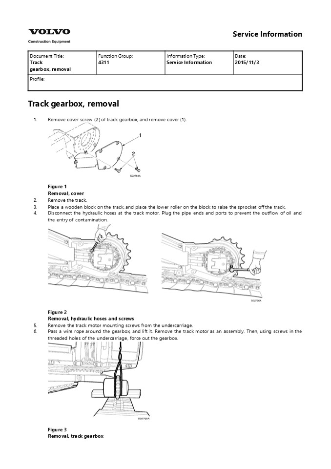
Track gearbox, removal 1. Remove cover screw (2)
of track gearbox, and remove cover (1).
- Figure 1 Removal, cover
- Remove the track.
- Place a wooden block on the track, and place the
lower roller on the block to raise the sprocket
off the track. - Disconnect the hydraulic hoses at the track
motor. Plug the pipe ends and ports to prevent
the outflow of oil and the entry of
contamination.
- Figure 2
- Removal, hydraulic hoses and screws
- Remove the track motor mounting screws from the
undercarriage. - Pass a wire rope around the gearbox, and lift it.
Remove the track motor as an assembly. Then,
using screws in the threaded holes of the
undercarriage, force out the gearbox.
Figure 3 Removal, track gearbox
2
NOTE! Lift the gearbox as close to the sprocket
as possible to maintain balance. NOTE! The
gearbox mounting screws may be used in the
threaded frame holes. NOTE! Putting matchmarks
on the track frame and track gearbox will
facilitate reassembly.
3
Service Information
Document Title Track gearbox (EC210), assembly Function Group 4311 Information Type Service Information Date 2015/11/3
Profile Profile Profile Profile
- Track gearbox (EC210), assembly
- Preparation
- Clean all parts with cleaning solvent and dry
with compressed air. - Rework damaged parts and before assembling,
prepare all replacement parts. - Coat the sliding parts, bearings and gears with
clean gear oil. - Coat the motor assembly sliding parts and
bearings with clean hydraulic oil. - Replace the o-rings, oil seal and seals.
- Replace screws (6). DO NOT REUSE THESE SCREWS !
- Use a torque wrench to tighten the screws and
plugs to the specified torque. - Tightening torque
Item No. Condition Standard value Allowable value, kgfm (lbfft)
6 Screw M12 11.5 (83)
30 Screw M12 13.5 (98)
31 Screw M10
32 Plug PT 1/2 6.6 (48)
NOTE! See Invalid linktarget . Assembly
procedure
No. Procedure Remark Tool
1 Pressfit angular bearing (2) into housing (1). The outer races of the angular bearing must be properly aligned and fully seated. Pressfit using a press or hammer. Plastic hammer Bench press
4
https//www.ebooklibonline.com Hello dear
friend! Thank you very much for reading. Enter
the link into your browser. The full manual is
available for immediate download. https//www.eb
ooklibonline.com
5
2 Press-fit seal (3) lightly into housing (1). Press-fit lightly seal (3) onto the motor casing (spindle 302). Assemble housing (1) onto the motor aligning the angular bearing inner race to the motor housing. After assembling the seal, check if the o-ring is properly seated on the motor housing. Apply a thin coat of grease (NLGI 2) to the o-ring. Take care not to damage the mating surface of the seal.
3 Shim adjusting method Measure the step on retainer (5) as shown. Dimension "B" Install retainer (5) with four screws (6), and tighten to the specified torque. Remove retainer (5) and measure from the top of the outer bearing race to the motor as shown. Dimension "A" Shim thickness S A B 0.05 mm Select a shim (4) of the appropriate thickness, align the retainer (5) correctly, and tighten screws (6) to the specified torque. Shim 0.1, 0.9, 1.0, and 1.2 mm Torque 0.8 kgfm (6 lbfft) Apply loctite 277 onto the thread of screws (6). 19 mm socket (M12) Torque wrench Depth gauge
Shim 0.1, 0.9, 1.0, and 1.2 mm Torque 0.8 kgfm (6 lbfft) Apply loctite 277 onto the thread of screws (6).
4 Mount parallel pin (7) into housing (1), align ring gear (8) correctly, and screws. Coat the mating surface of ring gear (8) with liquid gasket, loctite 5699. Install 4 screws (30) temporarily. Plastic hammer
5 No. 2 planetary gear assembly. Place No. 2 carrier (11) with its spline downward. Install thrust washers (14), No. 2 planetary gear (12) and needle bearing (13) into No. 2 carrier. Insert No. 2 pin (15). Tap spring pin (16) into the pin holes of the Check if No. 2 planetary gears rotate smoothly. Align the spring pin holes of the carrier and No. 2 pins. Staking method Plastic hammer
6
No. 2 carrier (11), and pin (15), then stake two
points on No. 2 carrier (11).
6 Fit No. 2 planetary gear assembly (10) into the
spline of the motor correctly.
Eye bolt(M10)
WARNING
The parts are heavy. Take appropriate safety
precautions.
7 Insert coupling(9), and then No.1 sun gear(27)
onto the motor shaft.
8 No. 1 planetary gear assembly.
Plastic
- Align the spring pin holes of the hammer
- Install thrust ring (17) into No. 1 carrier(19).
- Install assembled No. 1 carrier onto No. 2 sun
gear (20), and mount retaining ring (21). - Install thrust washers (24), No. 1 planetary
gear (22) and needle bearing (23) into No. 1
carrier (19). - Insert No. 1 pin (25).Tap spring pin (26) into
the pin holes of the No. 1 carrier (17) and pin
(25), then stake two points on No. 1
- carrier and No. 1 pins.
- Staking method
7
- carrier (19).
- Insert thrust ring (17) into No. 1 carrier (19).
- Check if No. 1 planetary gears rotate smoothly.
9 Insert No. 1 planetary gear assembly (18) into
No. 2 planetary gear assembly(10).
Eye bolt (M10)
WARNING
The parts are heavy. Take appropriate safety
precautions.
10 Screw an eye bolteye bolt into the oil level
port and install cover (28) on ring gear (8).
Install screw (31), screws (30), and tighten to
specified torque.
Eye bolt
- Coat the mating surface of ring gear (PT 1/2)
- (8) with liquid gasket, loctite 5699. L wrench
10
- Apply loctite 277 onto the threads mm (M12)
Torque wrench Plastic hammer
of screws (30).
11 Install plugs (32) into cover (28) and
tighten to Apply loctite 577 onto the threads of
plugs Torque
wrench L wrench 10 mm (PT1/2)
specified torque. (32).
8
- Fill port
- Level check port
- Drain port
9
Service Information
Document Title Track gearbox (EC210), description Function Group 4311 Information Type Service Information Date 2015/11/3
Profile Profile Profile Profile
Track gearbox (EC210), description Track gearbox
consists of a two stage planetary mechanism that
converts the high speed rotation of the hydraulic
motor, into low speed, high torque rotating
force at the sprocket hub.
- Figure 1
- 2 stage planetary gearbox
- Track motor
- No.1 planetary gear assembly
- No.2 planetary gear assembly
- Ring gear
10
- Figure 2
- Port connections
- Oil filling port (PT 1/2)
- Oil level check port (PT 1/2)
- Oil drain port (PT 1/2)
- Rotational direction
View from E axis Inlet Outlet
Clockwise A B
Counterclockwise B A
Port connections
Port symbol Port size Port
(A) (B) PF 1 Oil supply (Return)
(P1) (P2) PT1/4 Pressure check
(P) PF1/4 Displacement changeover valve oil supply
(D1) (D2) PF1/4 Drain
11
Figure 3 Track gearbox (EC210), sectional view
1 Housing 18 No.1 planetary gear assembly
2 Angular bearing 19 No.1 carrier
3 Seal 20 No.2 sun gear
4 Shim 21 Retaining ring gear
5 Retainer 22 No.1 planetary gear
6 Screw 23 No.1 needle bearing
7 Parallel pin 24 Thrust washer
8 Ring gear 25 No.1 pin
9 Coupling 26 Spring pin
10 No.2 planetary gear assembly 27 No.1 sun gear
11 No.2 carrier 28 Cover
12 No.2 planetary gear 29 Pad (thrust)
13 No.2 needle bearing 30 Screw
14 Thrust washer 31 Screw
15 No.2 pin 32 Plug
16 Spring pin 33 Name plate
17 Thrust ring
12
- Figure 4
- Track gearbox (EC210), exploded view
- The power transmitted from the hydraulic motor
output shaft is transmitted to the 1st stage sun
gear (27) ? spline of 1st carrier (19) ? 2nd sun
gear (20) ? 2nd planetary gear (12) ? ring gear
(8). - At this time, the reduction ratio of reduction
gear is as follows - 1st reduction ratio
- i1((Zs1 Zr) (Zs2 Zr) / (Zs1 Zs2)-1
- Zs1 No. of tooth of 1st sun gear
- Zs2 No. of tooth of 2nd sun gear
- Zr No. of tooth of ring gear
13
Figure 5 Track gearbox, torque flow
14
Service Information
Document Title Track gearbox (EC210), disassembly Function Group 4311 Information Type Service Information Date 2015/11/3
Profile Profile Profile Profile
- Track gearbox (EC210), disassembly
- Disassembly, precautions
- Thoroughly clean the gearbox assembly prior to
disassembly. - Select a clean work area.
- Match mark attached components to indicate proper
positioning during reassembly. - Take care not to mix parts of sub assemblies i.e.
planetary bearings, gears and thrust washers. - Thoroughly clean all parts and the inside of the
casings. - Inspect and analyze all failures. Determine the
root cause ! - NOTE!
- See Invalid linktarget .
- Disassembly procedure
No. Procedure Remark Tool
1 Place the oil fill port and the oil drain port on the vertical axis. Remove plug (32) and drain the gear oil. Drain oil into a clean container and check thoroughly for contamination. L wrench 10 mm (PT 1/2) 8 liter pan
Fill port Level check port Drain port
2 Remove screws (30) and remove cover (28). Install a screw (31) and carefully lift the cover off. L wrench 10 mm, 5 mm
15
Suggest For more complete manuals. Please go to
the home page. https//www.ebooklibonline.com If
the above button click is invalid. Please
download this document first, and then click the
above link to download the complete
manual. Thank you so much for reading
16
3 Remove No. 1 planetary gear assembly (18) from No. 2 planetary gear assembly (10). WARNING The parts are heavy. Take appropriate safety precautions. Eye bolt (M10) Plastic hammer
Disassemble No. 1 planetary gear assembly. Tap spring pin (26) into No. 1 pin (25). Remove thrust washer (24), No. 1 planetary gear (22) and needle bearing (23) from No. 1 carrier (19). Remove thrust ring (17). Remove retaining ring (21), then No. 2 sun gear (20). Remove thrust ring (17). Match mark gears (22), pins (25) and carrier (19). Do not mix the gears, bearings, thrust washers, and pin assemblies. Do not reuse spring pins (26).
4 Remove No. 1 sun gear (27) and coupling (9). Remove No. 1 carrier (19) and then remove No. 2, No. 1 sun gear (20, 27).
17
5 Remove No. 2 planetary gear assembly (10) from spindle (302). WARNING The parts are heavy. Take appropriate safety precautions. Match mark gears (12), pins (15) and carrier (11). Do not mix the gears, bearing, thrust washers, and pin assemblies. Do not reuse spring pins (16). Eye bolt (M10) Plastic hammer Eye bolt (M10) Plastic hammer
WARNING The parts are heavy. Take appropriate safety precautions. Match mark gears (12), pins (15) and carrier (11). Do not mix the gears, bearing, thrust washers, and pin assemblies. Do not reuse spring pins (16).
Disassembling No. 2 planetary gear assembly WARNING The parts are heavy. Take appropriate safety precautions. Match mark gears (12), pins (15) and carrier (11). Do not mix the gears, bearing, thrust washers, and pin assemblies. Do not reuse spring pins (16).
Tap spring pin (16) into No. 2 pin (15). Remove thrust washer (14), No. 2 planetary gear (12) and needle bearing (13) from No. 2 carrier (11). WARNING The parts are heavy. Take appropriate safety precautions. Match mark gears (12), pins (15) and carrier (11). Do not mix the gears, bearing, thrust washers, and pin assemblies. Do not reuse spring pins (16).
6 Screw the eye bolts into ring gear (8), and remove ring gear. Eye bolt (M12) Plastic hammer Eye bolt (M12) Plastic hammer
7 Remove screw (6), retainer (5) and shim (4). Do not reuse the screws. 19mm (M12) socket
18
https//www.ebooklibonline.com Hello dear
friend! Thank you very much for reading. Enter
the link into your browser. The full manual is
available for immediate download. https//www.eb
ooklibonline.com
Recommended

