
VOLVO EC210B NLC EC210BNLC EXCAVATOR Service Repair Manual Instant Download
Title:
VOLVO EC210B NLC EC210BNLC EXCAVATOR Service Repair Manual Instant Download
Description:
VOLVO EC210B NLC EC210BNLC EXCAVATOR Service Repair Manual Instant Download –
Number of Views:0
Title: VOLVO EC210B NLC EC210BNLC EXCAVATOR Service Repair Manual Instant Download
1
Service Information
Document Title Superstructure, removal Function Group 710 Information Type Service Information Date 2015/7/27
Profile EXC, EC210B NLC GB Profile EXC, EC210B NLC GB Profile EXC, EC210B NLC GB Profile EXC, EC210B NLC GB
Superstructure, removal Op nbr 00000
WARNING
- The superstructure is heavy. Pay attention to
safe footing and the area around the crane before
proceeding to remove or install the
superstructure. - NOTE!
- Weight of superstructure 4 7 tons excluding
counterweight and digging unit. - Remove the digging unit.
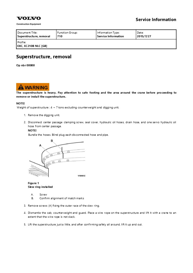
- Disconnect center passage clamping screw, seal
cover, hydraulic oil hoses, drain hose, and one
servo hydraulic oil hose from center passage. - NOTE!
- Bundle the hoses. Blind plug each disconnected
hose and pipe.
- Figure 1
- Slew ring installed
- Screw
- Confirm alignment of match marks
- Remove screws (A) fixing the outer race of the
slew ring. - Dismantle the cab, counterweight and guard. Place
a wire rope on the superstructure and lift it
with a crane to an extent that the wire rope is
not slack. - Lift the superstructure just a little, and after
confirming safety all around, lift it up and out.
2
Figure 2 Lifting the superstructure
3
Service Information
Document Title Superstructure, installation Function Group 710 Information Type Service Information Date 2015/7/27
Profile EXC, EC210B NLC GB Profile EXC, EC210B NLC GB Profile EXC, EC210B NLC GB Profile EXC, EC210B NLC GB
Superstructure, installation Op nbr 00000
- Bundle the hoses attached to the center passage
together and place them upright. - Coat the screws and threaded holes of the slew
ring with "Threebond kk 1215" (Loctite 515).
- Figure 1
- Fig. 5 Installing the superstructure
- Lift the superstructure and install it to the
slew ring. - NOTE!
- Lower the superstructure so that the slew pinion
and the slew ring are engaged. - NOTE!
- For tightening torque, see torque chart.
- NOTE!
- Tighten diagonally opposite screws in sequence.
- Connect the hoses, center passage clamping screw
and seal cover disconnected for removal.
4
https//www.ebooklibonline.com Hello dear
friend! Thank you very much for reading. Enter
the link into your browser. The full manual is
available for immediate download. https//www.eb
ooklibonline.com
5
Service Information
Document Title Tightening torque, specifications Function Group 715 Information Type Service Information Date 2015/7/27
Profile EXC, EC210B NLC GB Profile EXC, EC210B NLC GB Profile EXC, EC210B NLC GB Profile EXC, EC210B NLC GB
Tightening torque, specifications Protecting plate
Figure 1 Machine view, protecting
plate Tightening torque Nm (kgf m) (lbf ft)
No. Items Weight kg (lbs) Tightening torque
1 Mounting screws 265 29 (27 3) (195 22)
2 Track motor protection cover (LH, RH) 6.5 (14)
3 Mounting screws 262 26 (26.7 2.7) (193 19)
4 Under cover HDF (MUD) thick 20 91 (201)
NOTE! Apply loctite 277 or 609 on screws.
6
Service Information
Document Title Boom cylinder protecting guard, removal Function Group 715 Information Type Service Information Date 2015/7/27
Profile EXC, EC210B NLC GB Profile EXC, EC210B NLC GB Profile EXC, EC210B NLC GB Profile EXC, EC210B NLC GB
Boom cylinder protecting guard, removal Op nbr
715-019 1. Park the machine in the service
position B, see 091 Service positions.
- Figure 1
- Position, boom cylinders
- Raise boom cylinders (1), to Vertical position
and stop engine. - Install I-bolt and sling guard (2) securely with
a hoist. - NOTE!
- Guard weight 60 kg (132 lbs)
WARNING
The parts are heavy. Take appropriate safety
cautions when handling them. 4. Remove screws
(3) and guard (2).
Figure 2 Remove, guard
7
5. Remove screws (4) and clamps (5).
Figure 3 Remove, clamp
8
Service Information
Document Title Boom cylinder protecting guard, installation Function Group 715 Information Type Service Information Date 2015/7/27
Profile EXC, EC210B NLC GB Profile EXC, EC210B NLC GB Profile EXC, EC210B NLC GB Profile EXC, EC210B NLC GB
Boom cylinder protecting guard, installation Op
nbr 715-020 1. Park the machine in the service
position B, see 091 Service positions.
- Figure 1
- Marking, clamp position
- a. 405 5 mm (16 0.2 in)
- b. 745 5 mm (29.3 0.2 in)
- Raise boom cylinders (1), to Vertical position
and stop engine. - Mark clamp location on each the boom cylinder
(1). - Install screws (3) and clamps (2), don't over
tighten the clamps (2).
9
Figure 2 Install, clamp 5. Sling guard (4)
securely with a hoists and install screws (5).
Figure 3 Install, guard NOTE! Apply loctite on
screws (5). NOTE! Guard weight 60 kg (132
lbs) Tightening torque 262 26 Nm (193 19 lbf
ft)
WARNING
The parts are heavy. Take appropriate safety
cautions when handling them. 6. Before
installing screws (6) apply loctite.
10
Figure 4 Install, clamp screw NOTE! Tightening
torque 262 26 Nm (193 19 lbf ft) 7. Check
for interference of guard by operating the boom
cylinders.
11
Service Information
Document Title Bucket cylinder protecting guard, removal Function Group 715 Information Type Service Information Date 2015/7/27
Profile EXC, EC210B NLC GB Profile EXC, EC210B NLC GB Profile EXC, EC210B NLC GB Profile EXC, EC210B NLC GB
Bucket cylinder protecting guard, removal Op nbr
715-023 1. Park the machine in the service
position A, see 091 Service positions.
- Figure 1 Remove, cover
- Install I-bolts and sling guard (1) securely with
a hoist. Remove screws (2) and cover (3). - Remove screws (6) and guard (5).
Figure 2 Remove, guard
WARNING
The parts are heavy. Take appropriate safety
cautions when handling them. NOTE! Guard (5)
weight 113 kg (249 lbs) 4. Remove screws (6),
collars (7) and links (8).
12
Figure 3 Remove, links 5. Remove screws (9)
and plates (10).
Figure 4 Remove, plates 6. Remove screws (11)
and clamp (12).
Figure 5 Remove, clamp
13
Service Information
Document Title Bucket cylinder protecting guard, installation Function Group 715 Information Type Service Information Date 2015/7/27
Profile EXC, EC210B NLC GB Profile EXC, EC210B NLC GB Profile EXC, EC210B NLC GB Profile EXC, EC210B NLC GB
Bucket cylinder protecting guard, installation
Figure 1 Bucket cylinder protecting guard
No. Places. Gap clearances Gap clearances 1.0 mm thick shims 0.5 mm thick shims
No. Places. Minimum Maximum 1.0 mm thick shims 0.5 mm thick shims
Gap1 1 1.0 2.5 1 2
Gap2 1 2.0 3.5 2 2
Gap3 1 0.5 1.5 1
Gap4 1 0.5 1.5 1
NOTE! The item A it will have to consider to an
assembly direction. Op nbr 715-024 1. Park the
machine in the service position A, see 091
Service positions.
14
Suggest For more complete manuals. Please go to
the home page. https//www.ebooklibonline.com If
the above button click is invalid. Please
download this document first, and then click the
above link to download the complete
manual. Thank you so much for reading
15
- Figure 2 Install, clamp
- Install clamp (1) and screws (2).
- NOTE!
- Apply loctite on screws
- Tightening torque 111 11 Nm (82 8 lbf ft)
- Install plates (3) and screws (4).
Figure 3 Install, plates NOTE! Apply loctite on
screws Tightening torque 111 11 Nm (82 8 lbf
ft) 4. Install links (7), collars (6) and
screws (5).
16
Figure 4 Install, links 5. Install I-bolts and
sling guard (8) securely with a hoist.
Figure 5 Install, guard Install guard (8) and
screws (9). NOTE! Guard weight 113 kg (249
lbs) Tightening torque 262 26 Nm (193 19 lbf
ft)
WARNING
The parts are heavy. Take appropriate safety
cautions when handling them. 6. Install cover
(10), screws (11) and check for interference of
guard by operating the bucket cylinder.
Figure 6 Install, cover NOTE! Tightening
torque 262 26 Nm (193 19 lbf ft)
17
https//www.ebooklibonline.com Hello dear
friend! Thank you very much for reading. Enter
the link into your browser. The full manual is
available for immediate download. https//www.eb
ooklibonline.com
Recommended
CrystalGraphics Presentations


