
2006 Harley Davidson Sportster Service Repair Manual Instant Download PowerPoint PPT Presentation
Title: 2006 Harley Davidson Sportster Service Repair Manual Instant Download
1
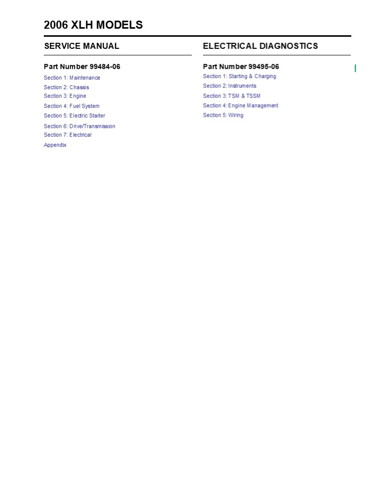
2006 XLH MODELS
SERVICE MANUAL
ELECTRICAL DIAGNOSTICS
Part Number 99484-06 Section 1
Maintenance Section 2 Chassis Section 3 Engine
Section 4 Fuel System Section 5 Electric
Starter Section 6 Drive/Transmission Section 7
Electrical Appendix
Part Number 99495-06 Section 1 Starting
Charging Section 2 Instruments Section 3 TSM
TSSM Section 4 Engine Management Section 5
Wiring
2
MAINTENANCE
1
Table Of Contents
- SUBJECT PAGE NO.
- General . . . . . . . . . . . . . . . . . . . . .
. . . . . . . . . . . . . . . . . . . . . . . . .
. . . . . . . . 1-1 - Fuel and Oil . . . . . . . . . . . . . . . . . .
. . . . . . . . . . . . . . . . . . . . . . . . .
. . . . . . . . 1-5 - Maintenance Schedule . . . . . . . . . . . . . .
. . . . . . . . . . . . . . . . . . . . . . . . .
. . . 1-6 - Critical Fasteners . . . . . . . . . . . . . . .
. . . . . . . . . . . . . . . . . . . . . . . . .
. . . . . . . 1-10 - Engine Oil and Filter . . . . . . . . . . . . . .
. . . . . . . . . . . . . . . . . . . . . . . . .
. . . . . 1-11 - Left Side Cover . . . . . . . . . . . . . . . . .
. . . . . . . . . . . . . . . . . . . . . . . . .
. . . . . . 1-14 - Battery Maintenance . . . . . . . . . . . . . . .
. . . . . . . . . . . . . . . . . . . . . . . . .
. . . . 1-16 - Brakes . . . . . . . . . . . . . . . . . . . . .
. . . . . . . . . . . . . . . . . . . . . . . . .
. . . . . . . . . 1-20 - Bleeding Hydraulic Brake System . . . . . . . . .
. . . . . . . . . . . . . . . . . . . . . . . .
. 1-21 - Brake Pads and Discs . . . . . . . . . . . . . .
. . . . . . . . . . . . . . . . . . . . . . . . .
. . . 1-24 - Tires and Wheels . . . . . . . . . . . . . . . .
. . . . . . . . . . . . . . . . . . . . . . . . .
. . . . . 1-31 - Primary Chain . . . . . . . . . . . . . . . . . .
. . . . . . . . . . . . . . . . . . . . . . . . .
. . . . . 1-33 - Clutch . . . . . . . . . . . . . . . . . . . . .
. . . . . . . . . . . . . . . . . . . . . . . . .
. . . . . . . . 1-35 - Transmission Lubricant . . . . . . . . . . . . .
. . . . . . . . . . . . . . . . . . . . . . . . .
. . . 1-37 - Rear Belt Deflection . . . . . . . . . . . . . .
. . . . . . . . . . . . . . . . . . . . . . . . .
. . . . . 1-39 - Rear Belt and Sprockets . . . . . . . . . . . . .
. . . . . . . . . . . . . . . . . . . . . . . . .
. . 1-43 - Shock Absorber Adjustment . . . . . . . . . . . .
. . . . . . . . . . . . . . . . . . . . . . . .
. 1-45
3
HOME GENERAL
1.1
Removing Parts Always consider the weight of a
part when lifting. Use a hoist whenever
necessary. Do not lift heavy parts by hand. A
hoist and adjustable lifting beam or sling are
needed to remove some parts. The lengths of
chains or cables from the hoist to the part
should be equal and parallel and should be posi-
tioned directly over the center of the part. Be
sure that no obstructions will interfere with the
lifting operation. Never leave a part suspended
in mid-air.
SERVICING A NEW MOTORCYCLE
?WARNING
WARNING
Perform the service and maintenance operations as
indi- cated in the regular service interval
table. Lack of regular maintenance at the
recommended intervals can affect the safe
operation of your motorcycle, which could result
in death or serious injury. (00010a)
?WARNING
WARNING
Service operations to be performed before
customer delivery are specified in the applicable
model year PREDELIVERY AND SETUP MANUAL. The
performance of new motorcycle initial service is
required to keep warranty in force and to ensure
proper emissions sys- tems operation. After a new
motorcycle has been driven its first 1000 miles
(1600 km), and at every 5000 mile (8000 km)
interval thereaf- ter, have a Harley-Davidson
dealer perform the service oper- ations listed
under 1.3 MAINTENANCE SCHEDULE.
Always check the capacity rating and condition of
hoists, slings, chains or cables before use.
Failure to do so could lead to an accident which
could result in death or serious injury.
Always use blocking or proper stands to support
the part that has been hoisted. If a part cannot
be removed, verify that all bolts and attaching
hardware have been removed. Check to see if any
parts are in the way of the part being
removed. When removing hoses, wiring or tubes,
always tag each part to ensure proper
installation. Cleaning If you intend to reuse
parts, follow good shop practice and thoroughly
clean the parts before assembly. Keep all dirt
out of parts the unit will perform better and
last longer. Seals, fil- ters and covers are used
in this vehicle to keep out environ- mental dirt
and dust. These items must be kept in good
condition to ensure satisfactory operation. Clean
and inspect all parts as they are removed. Be
sure all holes and passages are clean and open.
After cleaning, cover all parts with clean
lint-free cloth, paper or other mate- rial. Be
sure the part is clean when it is
installed. Always clean around lines or covers
before they are removed. Plug, tape or cap holes
and openings to keep out dirt, dust and
debris. Always verify cleanliness of blind holes
before assembly. Tightening a screw with dirt,
water or oil in the hole can cause castings to
crack or break.
SHOP PRACTICES
Repair Notes
- NOTES
- General maintenance practices are given in this
section. - Repair Disassembly/Assembly.
- Replace Removal/Installation.
- All special tools and torque values are noted at
the point of use. - All required parts or materials can be found in
the appropriate PARTS CATALOG. - Safety
- Safety is always the most important consideration
when per- forming any job. Be sure you have a
complete understanding of the task to be
performed. Use common sense. Use the proper
tools. Protect yourself and bystanders with
approved eye protection. Dont just do the job
do the job safely.
2006 Sportster Maintenance 1-1
4
https//www.ebooklibonline.com Hello dear
friend! Thank you very much for reading. Enter
the link into your browser. The full manual is
available for immediate download. https//www.ebo
oklibonline.com
5
HOME Disassembly and Assembly Always assemble or
disassemble one part at a time. Do not work on
two assemblies simultaneously. Be sure to make
all necessary adjustments. Recheck your work when
finished. Be sure that everything is
done. Operate the vehicle to perform any final
check or adjust- ments. If all is correct, the
vehicle is ready to go back to the
customer. Magnetic Parts Trays Magnetic parts
trays are becoming common in the service facility
because they are convenient and can keep parts
from becoming lost during a repair
procedure. However, hardened steel parts can
become magnetized when held in magnetic parts
trays. Metal fragments that would ordinarily be
washed away in the oil and trapped in the oil
filter or magnetic drain plug during vehicle
operation could be captured by magnetized parts
in the engine, potentially causing accelerated
engine wear and damage. Parts that will be
returned to service inside the vehicles pow-
ertrain such as gears, thrust washers and
especially bearings should never be kept in
magnetic parts trays.
Bearings Anti-friction bearings must be handled
in a special way. To keep out dirt and abrasives,
cover the bearings as soon as they are removed
from the package. Wash bearings in a
non-flammable cleaning solution. Knock out packed
lubricant inside by tapping the bearing against a
wooden block. Wash bearings again. Cover bearings
with clean material after setting them down to
dry. Never use com- pressed air to dry
bearings. Coat bearings with clean oil. Wrap
bearings in clean paper. When bearings are
installed against shoulders, be sure that the
chamfered side of the bearing always faces the
shoulder. Lubricate bearings and all metal
contact surfaces before pressing into place. Only
apply pressure on the part of the bearing that
makes direct contact with the mating part. Always
use the proper tools and fixtures for removing
and installing bearings. Bearings do not usually
need to be removed. Only remove bearings if
necessary. Bushings Do not remove a bushing
unless damaged, excessively worn or loose in its
bore. Press out bushings that must be
replaced. When pressing or driving bushings, be
sure to apply pressure in line with the bushing
bore. Use a bearing/bushing driver or a bar with
a smooth, flat end. Never use a hammer to drive
bushings. Inspect the bushing and the mated part
for oil holes. Be sure all oil holes are properly
aligned. Gaskets Always discard gaskets after
removal. Replace with new gas- kets. Never use
the same gasket twice. Be sure that gasket holes
match up with holes in the mating part. Lip Type
Seals Lip seals are used to seal oil or grease
and are usually installed with the sealing lip
facing the contained lubricant. Seal orientation,
however, may vary under different applica-
tions. Seals should not be removed unless
necessary. Only remove seals if required to gain
access to other parts or if seal dam- age or wear
dictates replacement. Leaking oil or grease
usually means that a seal is damaged. Replace
leaking seals to prevent overheated
bearings. Always discard seals after removal. Do
not use the same seal twice.
REPAIR AND REPLACEMENT PROCEDURES
Hardware and Threaded Parts Install helical
thread inserts when inside threads in castings
are stripped, damaged or not capable of
withstanding speci- fied torque. Replace bolts,
nuts, studs, washers, spacers and small com- mon
hardware if missing or in any way damaged. Clean
up or repair minor thread damage with a suitable
tap or die. Replace all damaged or missing
lubrication fittings. Use Teflon pipe sealant on
pipe fitting threads. Wiring, Hoses and
Lines Replace hoses, clamps, electrical wiring,
electrical switches or fuel lines if they do not
meet specifications. Instruments and
Gauges Replace broken or defective
instruments and gauges. Replace dials and glass
that are so scratched or discolored that reading
is difficult.
1-2 2006 Sportster Maintenance
6
HOME O-Rings (Preformed Packings) Always discard
O-rings after removal. Replace with new O- rings.
To prevent leaks, lubricate the O-rings before
installa- tion. Apply the same type of lubricant
as that being sealed. Be sure that all gasket,
O-ring and seal mating surfaces are thoroughly
clean before installation. Gears Always check
gears for damaged or worn teeth. Lubricate mating
surfaces before pressing gears on
shafts. Shafts If a shaft does not come out
easily, check that all nuts, bolts or retaining
rings have been removed. Check to see if other
parts are in the way before using force. Shafts
fitted to tapered splines should be very tight.
If shafts are not tight, disassemble and inspect
tapered splines. Dis- card parts that are worn.
Be sure tapered splines are clean, dry and free
of burrs before putting them in place. Press mat-
ing parts together tightly. Clean all rust from
the machined surfaces of new parts. Part
Replacement Always replace worn or damaged parts
with new parts.
Rust or Corrosion Removal Remove rust and
corrosion with a wire brush, abrasive cloth, sand
blasting, vapor blasting or rust remover. Use
buffing cro- cus cloth on highly polished parts
that are rusted. Bearings Clean open bearings by
soaking them in a petroleum clean- ing solution.
Never use a solution that contains chlorine. Let
bearings stand and dry. Do not dry with
compressed air. Do not spin bearings while they
are drying.
TOOL SAFETY
Air Tools
- Always use approved eye protection equipment when
performing any task using air-operated tools. - On all power tools, use only recommended
accessories with proper capacity ratings. - Do not exceed air pressure ratings of any power
tools. - Bits should be placed against work surface before
air hammers are operated. - Disconnect the air supply line to an air hammer
before attaching a bit. - Never point an air tool at yourself or another
person. - Protect bystanders with approved eye protection.
CLEANING
Part Protection Before cleaning, protect rubber
parts (such as hoses, boots and electrical
insulation) from cleaning solutions. Use a
grease-proof barrier material. Remove the rubber
part if it cannot be properly protected. Cleaning
Process Any cleaning method may be used as long
as it does not result in parts damage. Thorough
cleaning is necessary for proper parts
inspection. Strip rusted paint areas to bare
metal before repainting.
Wrenches
- Never use an extension on a wrench handle.
- If possible, always pull on a wrench handle and
adjust your stance to prevent a fall if something
lets go. - Never cock a wrench.
- Never use a hammer on any wrench other than a
STRIK- ING FACE wrench. - Discard any wrench with broken or battered
points. - Never use a pipe wrench to bend, raise or lift a
pipe.
2006 Sportster Maintenance 1-3
7
- HOME
- Pliers/Cutters/Prybars
- Plastic- or vinyl-covered pliers handles are not
intended to act as insulation dont use on live
electrical circuits. - Dont use pliers or cutters for cutting hardened
wire unless they were designed for that purpose. - Always cut at right angles.
- Dont use any prybar as a chisel, punch or
hammer. - Hammers
- Never strike a hammer against a hardened object,
such as another hammer. - Always grasp a hammer handle firmly, close to the
end. - Strike the object with the full face of the
hammer. - Never work with a hammer which has a loose head.
- Discard hammer if face is chipped or mushroomed.
- Wear approved eye protection when using striking
tools. - Protect bystanders with approved eye protection.
- Punches/Chisels
- Never use a punch or chisel with a chipped or
mush- roomed end dress mushroomed chisels and
punches with a file. - Hold a chisel or a punch with a tool holder if
possible. - When using a chisel on a small piece, clamp the
piece firmly in a vise and chip toward the
stationary jaw. - Wear approved eye protection when using these
tools.
Ratchets and Handles
- Periodically clean and lubricate ratchet
mechanisms with a light grade oil. Do not replace
parts individually ratch- ets should be rebuilt
with the entire contents of service kit. - Never hammer or put a pipe extension on a ratchet
or handle for added leverage. - Always support the ratchet head when using socket
extensions, but do not put your hand on the head
or you may interfere with the action of its
reversing mechanism. - When breaking loose a fastener, apply a small
amount of pressure as a test to be sure the
ratchets gear wheel is engaged with the pawl.
?
?
?
Sockets
- Never use hand sockets on power or impact
wrenches. - Select the right size socket for the job. Never
cock any wrench or socket. - Select only impact sockets for use with air or
electric impact wrenches. - Replace sockets showing cracks or wear.
- Keep sockets clean.
- Always use approved eye protection when using
power or impact sockets.
?
?
Storage Units
- Dont open more than one loaded drawer at a time.
Close each drawer before opening up another. - Close lids and lock drawers and doors before
moving storage units. - Dont pull on a tool cabinet push it in front of
you. - Set the brakes on the locking casters after the
cabinet has been rolled to your work.
?
- Dont use a screwdriver for prying, punching,
chiseling, scoring or scraping. - Use the right type of screwdriver for the job
match the tip to the fastener. - Dont interchange POZIDRIV, PHILLIPS or REED
AND PRINCE screwdrivers. - Screwdriver handles are not intended to act as
insula- tion dont use on live electrical
circuits. - Dont use a screwdriver with rounded edges
because it will slip redress with a file.
?
?
?
?
1-4 2006 Sportster Maintenance
8
HOME FUEL AND OIL
1.2
FUEL
ENGINE OIL
Harley-Davidson motorcycles were designed to
obtain the best performance and efficiency using
unleaded gasoline (91 pump octane or higher for
the XL 1200 Custom and XL 1200 Roadster, 87 or
higher for all other models). Pump octane is the
octane number usually shown on the gas pump. Some
fuel suppliers sell gasoline/alcohol blends as a
fuel. The type and amount of alcohol added to the
fuel is important.
Use the proper grade of oil for the lowest
temperature expected before the next oil
change. If it is necessary to add oil and
Harley-Davidson oil is not available, use an oil
certified for diesel engines. Acceptable diesel
engine oil designations include CF, CF-4, CG-4
and CH-4. The preferred viscosities for the
diesel engine oils, in descending order, are
20W-50, 15W-40 and 10W-40. At the first
opportunity, see a Harley-Davidson dealer to
change back to 100 percent Harley-Davidson
oil. See 1.5 ENGINE OIL AND FILTER for all
service information.
?WARNING
WARNING
Avoid spills. Slowly remove filler cap. Do not
fill above bot- tom of filler neck insert,
leaving air space for fuel expan- sion. Secure
filler cap after refueling. Gasoline is
extremely flammable and highly explosive, which
could result in death or serious injury. (00028a)
WINTER LUBRICATION
Normal fuel combustion in a gasoline engine
produces water vapor and carbon dioxide along
with other gases and particu- lates. During
starting and warm-up in cold weather,
especially in freezing temperatures, the
vapor condenses to water before the crankcase is
hot enough to exhaust it through the breather
system. If the engine is driven long enough to
thor- oughly warm the crankcase, most of this
liquid water is again vaporized and exhausted
through the crankcase breather system. A
moderately driven vehicle making short runs may
not be able to vacate water vapors allowing
liquid water to accumu- lates in the oil tank.
This is especially true if the vehicle is
operated in cold weather. In freezing weather, an
accumula- tion of water in the engine oil may
become slush or ice, which can block oil lines
and lead to severe engine damage. Water remaining
in the engine oil for long periods of time can
form an acidic sludge that is corrosive to metal
engine parts and causes accelerated wear of
moving components. Always change the engine oil
more often in winter. The colder the weather, the
shorter the recommended oil change inter- val. If
the engine is used for short runs, change the oil
even more frequently.
GASOLINE BLENDS
CAUTION
Do not use gasoline that contains methanol. Doing
so can result in fuel system component failure,
engine dam- age and/or equipment malfunction.
(00148a) Harley-Davidson motorcycles are designed
to give the best performance using unleaded
gasoline. Some fuel suppliers sell
gasoline/alcohol blends as a fuel. The type and
amount of alcohol added to the fuel is important.
- DO NOT USE GASOLINES CONTAINING METHANOL.
- Using gasoline/methanol blends will result in
starting and driveability deterioration and
damage to critical fuel sys- tem components. - ETHANOL is a mixture of 10 ethanol (Grain
alcohol) and 90 unleaded gasoline. It is
identified as gasohol, ethanol enhanced, or
contains ethanol. Gasoline/etha- nol blends can
be used in your motorcycle if the ethanol content
does not exceed 10. - REFORMULATED OR OXYGENATED GASOLINES
- (RFG) Reformulated gasoline is a term used to
describe gasoline blends that are specifically
designed to burn cleaner than other types of
gasoline. Your motorcy- cle will run normally
using this type of gasoline.
Because of their generally higher volatility,
these blends may adversely affect the starting,
driveability and fuel efficiency of your
motorcycle. If you experience these problems,
Harley- Davidson recommends you operate your
motorcycle on straight, unleaded gasoline.
2006 Sportster Maintenance 1-5
9
HOME MAINTENANCE SCHEDULE
1.3
GENERAL
If more detailed information is needed, turn to
the sections which follow for step-by-step
instructions. Also, throughout this manual, you
will be instructed to use various lubricants,
greases and sealants. Refer to Table 1-3. for the
correct part numbers of these items.
The table below lists the periodic maintenance
requirements for Sportster model motorcycles. If
you are familiar with the procedures, just refer
to the table for the recommended ser- vice
interval. If necessary, see the quick reference
table (Table 1-2.) on page 1-8 for the required
specifications.
Table 1-1. Regular Service Intervals For
Sportster Models
ITEM SERVICED PROCEDURE 1000 MI 1600 KM 5000 MI 8000 KM 10,000 MI 16,000 KM 15,000 MI 24,000 KM 20,000 MI 32,000 KM 25,000 MI 40,000 KM NOTES
Engine oil and filter Replace X X X X X X
Oil lines and brake system Inspect for leaks X X X X X X 1
Air cleaner Inspect, service as required X X X X X X
Tires Check pressure, inspect tread X X X X X X
Wheel spokes Check tightness X X X X X X 1, 4
Transmission lubricant Replace X X X
Clutch Check adjustment X X X X X X 1
Primary chain Check adjustment X X X X X X
Rear belt and sprockets Inspect, adjust belt X X X X X X 1
Throttle, brake, enrichener and clutch controls Check, adjust and lubricate X X X X X X 1
Jiffy stand Inspect and lubricate X X X 1
Fuel valve, lines and fittings Inspect for leaks X X X X X X 1
Fuel tank filter screen Clean X 1
Brake fluid Check levels and condition X X X X X X
Brake pads and discs Inspect for wear X X X X X X
Front brake lever pin Inspect X X X X 1, 2
Front brake lever pin Lubricate X 1, 2
Brake caliper pins Inspect X X X X 1, 2
Brake caliper pins Lubricate X 1, 2
Brake caliper boots and bush- ings Inspect X X X X 1, 2
Brake caliper boots and bush- ings Replace X 1, 2
Rear master cylinder outer boot Inspect X X X X X 1, 2
Brake components Replace brake rubber components in master cylinders and calipers X 1, 2
Brake components Lubricate master cylinder pistons X 1, 2
Spark plugs Inspect X X X X
Spark plugs Replace X X
Electrical equipment and switches Check operation X X X X X X
Engine idle speed Check adjustment X X X X X X 1
Front fork oil Replace X 1
Steering head bearings Adjust X X 1
Steering head bearings Lubricate X 1
1-6 2006 Sportster Maintenance
10
HOME
Table 1-1. Regular Service Intervals For
Sportster Models
ITEM SERVICED PROCEDURE 1000 MI 1600 KM 5000 MI 8000 KM 10,000 MI 16,000 KM 15,000 MI 24,000 KM 20,000 MI 32,000 KM 25,000 MI 40,000 KM NOTES
Rear fork bearings Replace every 30,000 mi (48,000 km) Replace every 30,000 mi (48,000 km) Replace every 30,000 mi (48,000 km) Replace every 30,000 mi (48,000 km) Replace every 30,000 mi (48,000 km) Replace every 30,000 mi (48,000 km) 1
Shock absorbers Inspect X X X X X X 1
Critical fasteners Check tightness X X X 1
Engine mounts and stabilizer links Inspect X X 1
Battery Check battery and clean connections 3
Road test Verify component and system functions X X X X X X
NOTES Should be performed by an authorized Harley-Davidson dealer, unless you have the proper tools, service data and are mechanically qualified. Replace every four (4) years. Perform annually. Not all vehicles are equipped with spoke wheels. Consult appropriate topic in service manual. Should be performed by an authorized Harley-Davidson dealer, unless you have the proper tools, service data and are mechanically qualified. Replace every four (4) years. Perform annually. Not all vehicles are equipped with spoke wheels. Consult appropriate topic in service manual. Should be performed by an authorized Harley-Davidson dealer, unless you have the proper tools, service data and are mechanically qualified. Replace every four (4) years. Perform annually. Not all vehicles are equipped with spoke wheels. Consult appropriate topic in service manual. Should be performed by an authorized Harley-Davidson dealer, unless you have the proper tools, service data and are mechanically qualified. Replace every four (4) years. Perform annually. Not all vehicles are equipped with spoke wheels. Consult appropriate topic in service manual. Should be performed by an authorized Harley-Davidson dealer, unless you have the proper tools, service data and are mechanically qualified. Replace every four (4) years. Perform annually. Not all vehicles are equipped with spoke wheels. Consult appropriate topic in service manual. Should be performed by an authorized Harley-Davidson dealer, unless you have the proper tools, service data and are mechanically qualified. Replace every four (4) years. Perform annually. Not all vehicles are equipped with spoke wheels. Consult appropriate topic in service manual. Should be performed by an authorized Harley-Davidson dealer, unless you have the proper tools, service data and are mechanically qualified. Replace every four (4) years. Perform annually. Not all vehicles are equipped with spoke wheels. Consult appropriate topic in service manual. Should be performed by an authorized Harley-Davidson dealer, unless you have the proper tools, service data and are mechanically qualified. Replace every four (4) years. Perform annually. Not all vehicles are equipped with spoke wheels. Consult appropriate topic in service manual.
2006 Sportster Maintenance 1-7
11
HOME
Table 1-2. Quick Reference Maintenance Chart
ITEM SERVICED SPECIFICATION DATA
Engine oil and filter Oil capacity 3.6 qt. (3.4 L)
Engine oil and filter Filter Hand tighten 1/2-3/4 turn after gasket contact
Engine oil and filter Chrome filter (XL 1200C) Part no. 63796-77A
Engine oil and filter Black filter (all except XL 1200C) Part no. 63805-80A
Primary chain tension Deflection with hot engine 1/4-3/8 in. (6.3-9.5 mm)
Primary chain tension Deflection with cold engine 3/8-1/2 in. (9.5-12.7 mm)
Primary chain tension Chain tensioner nut torque 20-25 ft-lbs (27.1-33.9 Nm)
Primary chain tension Primary chain inspection cover torque 40-60 in-lbs (4.5-6.8 Nm)
Primary chain/ transmission lubricant Lubricant capacity 32 oz. (946 mL)
Primary chain/ transmission lubricant Primary chaincase drain plug torque 14-30 ft-lbs (19.0-40.7 Nm)
Primary chain/ transmission lubricant Lubricant Genuine Harley-Davidson Formula Transmission and Primary Chaincase Lubricant
Clutch adjustment Free play at adjuster screw 1/4 turn
Clutch adjustment Free play at hand lever 1/16-1/8 (1.6-3.2 mm)
Clutch adjustment Clutch inspection cover torque 84-108 in-lbs (9.5-12.2 Nm)
Tire condition and pressure Pressure for solo rider Front 30 psi (207 kPa), Rear 36 psi (248 kPa)
Tire condition and pressure Pressure for rider and passenger Front 30 psi (207 kPa), Rear 40 psi (276 kPa)
Tire condition and pressure Wear Replace tire if 1/32 in. (0.8 mm) or less of tread pattern remains
Wheel spokes Spoke nipple torque 40-50 in-lbs (4.5-5.7 Nm)
Steering head bearings Lubricant for neck fitting SPECIAL PURPOSE GREASE
Brake fluid reservoir level Brake fluid type D.O.T. 5 brake fluid
Brake fluid reservoir level Proper fluid level (front brake) 1/4 in. (6 mm) from the top of the reservoir
Brake fluid reservoir level Proper fluid level (rear brake) Upper fluid level in reservoir
Brake fluid reservoir level Front master cylinder reservoir cover screws 9-17 in-lbs (1.0-2.0 Nm)
Brake pad linings and discs Minimum brake pad thickness 0.04 in. (1.02 mm)
Brake pad linings and discs Minimum brake disc thickness See stamp on side of disc
Drive belt Upward measurement force applied at midpoint of bottom belt strand 10 lb. (4.5 kg)
Drive belt Belt deflection with motorcycle on jiffy stand, belt and sprockets at ambient temperature (cold engine), without rider or luggage XL 883L/XL 883C/XL 1200C 1/4-5/16 in. (6.4-7.9 mm)
Drive belt Belt deflection with motorcycle on jiffy stand, belt and sprockets at ambient temperature (cold engine), without rider or luggage XL 883/XL 883R/XL 1200R 3/8-7/16 in. (9.5-11.1 mm)
Air cleaner Air filter element screw torque 40-60 in-lbs (4.5-6.8 Nm)
Air cleaner Air cleaner cover screw torque 30-60 in-lbs (4.1-6.8 Nm)
Enrichener control Hex nut torque 20-35 in-lbs (2.3-4.0 Nm)
Engine idle speed Idle speed 950-1050 RPM
1-8 2006 Sportster Maintenance
12
HOME
Table 1-2. Quick Reference Maintenance Chart
ITEM SERVICED SPECIFICATION DATA
Fuel tank filter Sealant for fuel valve and fuel tank adapter LOCTITE PIPE SEALANT WITH TEFLON 565 Part no. 99818-97 (6 ml)
Fuel tank filter Hex jam nut torque 15-20 ft-lbs (20.3-27.1 Nm)
Clutch and throttle cables Lubricant SUPER OIL
Clutch and throttle cables Handlebar clamp screw torque 108-132 in-lbs (12.2-14.9 Nm)
Clutch and throttle cables Handlebar switch housing screw torque 35-45 in-lbs (3.9-5.0 Nm)
Spark plugs Type HD-6R12
Spark plugs Gap 0.038-0.043 in. (0.96-1.09 mm)
Spark plugs Torque 12-18 ft-lbs (16.3-24.4 Nm)
Front fork oil Type HYDRAULIC FORK OIL (TYPE E)
Front fork oil Amount See 1.20 FRONT FORK OIL
Battery Lubricant ELECTRICAL CONTACT LUBRICANT
Battery Terminal screw torque 40-50 in-lbs (4.5-5.7 Nm)
Critical fasteners See 1.4 CRITICAL FASTENERS See 1.4 CRITICAL FASTENERS
Engine mounts/isolators and Stabilizers See 2.22 FRONT ENGINE MOUNT/ISOLATOR, 2.23 REAR ENGINE MOUNT/ISOLATOR, 2.21 STABILIZER LINKS See 2.22 FRONT ENGINE MOUNT/ISOLATOR, 2.23 REAR ENGINE MOUNT/ISOLATOR, 2.21 STABILIZER LINKS
Table 1-3. Lubricants, Greases, Sealants
ITEM PART NUMBER PACKAGE
Anti-Seize Lubricant 98960-97 1 oz squeeze tube
D.O.T. 5 Brake Fluid 99902-77 12 oz. bottle
D.O.T. 5 Brake Fluid 99901-77 1 gal
Electrical Contact Lubricant 99861-02 1 oz squeeze tube
Genuine Harley-Davidson Formula Transmission and Primary Chaincase Lubricant 99851-05 1 qt bottle
G40M Brake Grease 42820-04 squeeze packet
Gray High Performance Sealant 99650-02 1.9 oz squeeze tube
HYLOMAR Gasket and Thread Sealant 99653-85 3.5 oz tube
Loctite Pipe Sealant With Teflon 565 99818-97 6 ml squeeze tube
Loctite Prism Primer (770)
Loctite Prism Superbonder (411)
Loctite Superbonder 420 Adhesive
Loctite Threadlocker 243 (blue) 99642-97 6 ml squeeze tube
Loctite Threadlocker 262 (red) 94759-99 6 ml squeeze tube
Loctite Threadlocker 272 98618-03 10 ml bottle
Special Purpose Grease 99857-97 14 oz. cartridge
Super Oil 94968-85TV 1/4 fl. oz
Type E Hydraulic Fork Oil 99884-80 16 oz bottle
2006 Sportster Maintenance 1-9
13
HOME CRITICAL FASTENERS
1.4
INSPECTION
Refer to Table 1-4. Tighten all critical
fasteners, except head bolts, to service manual
specifications. Replace any dam- aged or missing
hardware.
Inspect critical fasteners, except head bolts.
Table 1-4. Critical Fasteners
SYSTEM FASTENER TORQUE TORQUE
Hand controls Upper and lower switch housing screws 35-45 in-lbs 3.9-5.0 Nm
Hand controls Clutch lever handlebar clamp screws 108-132 in-lbs 12.2-14.9 Nm
Hand controls Master cylinder handlebar clamp screws 108-132 in-lbs 12.2-14.9 Nm
Engine Stabilizer link screws 25-35 ft-lbs 33.9-47.5 Nm
Engine Upper front stabilizer link-to-frame mounting bracket screws 25-35 ft-lbs 33.9-47.5 Nm
Engine Upper front stabilizer link-to-engine mounting bracket screws 55-65 ft-lbs 74.6-88.2 Nm
Engine Lower front stabilizer link-to-frame mounting bracket screws 25-35 ft-lbs 33.9-47.5 Nm
Engine Front isolator mounting bolt 60-70 ft-lbs 81.4-95.0 Nm
Engine Rear isolator/rear fork pivot shaft bolts 60-70 ft-lbs 81.4-95.0 Nm
Engine Front isolator mounting bracket screws (left side) 25-35 ft-lbs 33.9-47.5 Nm
Engine Rear isolator mounting bracket screws (left side) 25-35 ft-lbs 33.9-47.5 Nm
Brakes Brake line banjo bolts 20-25 ft-lbs 27.1-33.9 Nm
Brakes Brake disc mounting screws, front 16-24 ft-lbs 21.7-32.5 Nm
Brakes Brake disc mounting screws, rear 30-45 ft-lbs 40.7-61.0 Nm
Brakes Front master cylinder reservoir cover screws 9-17 in-lbs 1.0-2.0 Nm
Brakes Rear master cylinder mounting screws 15-20 ft-lbs 20.3-27.1 Nm
Brakes Rear master cylinder bracket-to-frame mounting screws 17-22 ft-lbs 23.1-29.9 Nm
Brakes Front brake caliper mounting screws 28-38 ft-lbs 38.0-51.6 Nm
Axle nuts Front axle 50-55 ft-lbs 67.8-74.6 Nm
Axle nuts Rear axle 72-78 ft-lbs 98-106 Nm
Front fork/ handlebars Lower bracket pinch screws 30-35 ft-lbs 40.7-47.5 Nm
Front fork/ handlebars Upper bracket pinch screws 30-35 ft-lbs 40.7-47.5 Nm
Front fork/ handlebars Steering stem bolt 15 ft-lbs, loosen, 7 ft-lbs 20.4 Nm, loosen, 9.5 Nm
Front fork/ handlebars Steering stem pinch screw 30-35 ft-lbs 40.7-47.5 Nm
Front fork/ handlebars Front axle pinch screw 21-27 ft-lbs 28.5-36.6 Nm
Front fork/ handlebars Handlebar clamp mounting screw 12-18 ft-lbs 16.3-24.4 Nm
Front fork/ handlebars Riser mounting bolts 30-40 ft-lbs 40.7-54.3 Nm
Final drive Rear sprocket mounting bolts 55-65 ft-lbs 74.6-88.2 Nm
1-10
2006 Sportster Maintenance
14
HOME ENGINE OIL AND FILTER
1.5
CHECKING AND ADDING OIL
11310
- Check engine oil level in oil tank and add oil if
necessary. Oil tank capacity is 3.6 quarts (U.S.)
(3.4 liters). Refer to Table 1- - 5. on the next page for recommended engine oil
viscosity. - Removing and Replacing Oil Filler Cap
- See Figure 1-1. Remove filler cap from oil tank
on right side of vehicle. - Press straight down on filler cap and release.
Cap will pop up. - Pull up on filler cap while turning
counterclockwise one-quarter turn as if
unscrewing filler cap. - Wipe attached dipstick clean.
- NOTE
- See Figure 1-2. Note that dipstick has a wide
slot (1) and a narrow slot (2) and can only be
inserted in oil tank one way. - Insert dipstick into tank. Turn filler cap
clockwise one- quarter turn as if screwing filler
cap into tank. When filler cap stops turning, it
is fully seated. Press down on filler cap until
it snaps in place, flush with top of oil tank
cover. - Checking Oil With Cold Engine
Figure 1-1. Filler Cap/Dipstick Location
- x0575x1x
- 1
- 2
- Wide slot
- Narrow slot
- Position motorcycle so that it is leaning on
jiffy stand. - Remove filler cap. See Removing and Replacing Oil
Filler Cap above. Wipe attached dipstick clean.
Reinstall oil filler cap in tank. - Remove oil filler cap again and check oil level
on dipstick. See Figure 1-3. Dipstick has two
marks. If oil level is at or below lower mark
(2), add only enough oil to bring the level to a
point between the two arrows on the dipstick.
Replace filler cap.
Checking Oil With Warm Engine
Figure 1-2. Filler Cap/Dipstick
- Run engine until engine oil is at normal
operating tem- perature. Turn engine off. - Position motorcycle so that it is leaning on
jiffy stand. - Remove filler cap. See Removing and Replacing
Oil Filler Cap above. Wipe attached dipstick
clean. Reinstall oil filler cap in tank. - Remove filler cap again and check warm oil level
on dip- stick. See Figure 1-3. Dipstick has two
marks. If oil level in tank is at or below lower
mark, add one quart (0.946 liter) of
Harley-Davidson oil to tank. Replace filler cap. - If you added oil in step 4, remove filler cap and
verify cor- rect engine oil level in oil tank. Do
not fill oil tank to a level above upper mark on
dipstick. Replace filler cap.
x0576x1x
1
- 2
- Upper mark (full)
- Lower mark
Figure 1-3. Checking Oil Level
2006 Sportster Maintenance
1-11
15
HOME
Table 1-5. Recommended Engine Oil Viscosity
HARLEY-DAVIDSON TYPE VISCOSITY HARLEY-DAVIDSON RATING LOWEST AMBIENT TEMPERATURE COLD WEATHER STARTS BELOW 50F (10C)
HD Multigrade SAE 10W40 HD 360 Below 40 F (4 C) Excellent
HD Multigrade SAE 20W50 HD 360 Above 40 F (4 C) Good
HD Regular Heavy SAE 50 HD 360 Above 60 F (16 C) Poor
HD Extra Heavy SAE 60 HD 360 Above 80 F (27 C) Poor
CHANGING OIL AND FILTER
- Loosen worm drive clamp (2) and pull drain plug
(3) from end of drain hose. Completely drain
engine oil from oil tank. It is not necessary to
drain engine crankcase. - Replace drain plug into end of drain hose and
tighten worm drive clamp securely.
General
PART NO. SPECIALTY TOOL
HD-42311 or HD-44067-A Oil filter wrench
- 11763
- 1
- 2
- Completely drain oil tank of used oil at
scheduled service intervals as specified in 1.3
MAINTENANCE SCHEDULE. Refer to Table 1-1. Refill
with fresh oil. - NOTES
- If vehicle is driven extremely hard, used in
competition, or driven on dusty roads, change
engine oil at shorter intervals. - Always change oil filter when changing engine
oil. - Draining Oil Tank
- Run engine until engine oil has reached normal
operat- ing temperature. - NOTE
- Oil will drain more quickly if filler
cap/dipstick is removed from oil tank as
described on previous page. - See Figure 1-4. Place a suitable container
directly under the drain hose (1) at the bottom
rear of the engine crank- case. The container
must be able to hold approximately four quarts
(U.S.) (3.8 liters).
Figure 1-4. Oil Tank Drain Hose
1-12
2006 Sportster Maintenance
16
HOME Removing Oil Filter
Installing New Oil Filter NOTE Partially fill oil
filter before installation to minimize the time
required for buildup of oil pressure when engine
is first started.
- Place a drain pan beneath front of engine
crankcase. - See Figure 1-5. See Figure 1-6. Remove oil filter
using HARLEY-DAVIDSON OIL FILTER WRENCH. Turn oil
fil- - ter counterclockwise to remove from filter mount.
- Drain oil filter into drain pan. Discard oil
filter. - Clean any oil spills off crankcase and frame.
- Pour about 4 fluid ounces (U.S.) (120 ml) of
fresh, clean engine oil into new oil filter.
Allow time for oil to soak into filter element. - Wipe filter gasket contact surface of oil filter
mount with a clean cloth. - See Figure 1-7. Coat oil filter gasket with clean
Harley- Davidson 20W-50 engine oil. - NOTE
- 1
- 2
- Oil filter mount
- Oil filter
11352
Do not use oil filter wrench to install new oil
filter. 4. Install new oil filter. Turn filter
clockwise to install. Hand tighten filter 1/2 to
3/4-turn after gasket contacts filter mount
surface.
d0384x1x
Figure 1-5. Oil Filter
h42311 hd44067
Figure 1-7. Lubricating New Oil Filter Gasket
Refilling Oil Tank
- Refer to Table 1-5. Always use the proper grade
of oil for the lowest expected air temperature
before the next reg- ularly scheduled oil change.
Pour 3.6 quarts (U.S.) (3.4 liters) of oil into
engine oil tank minus the 4 fl. oz. (120 ml)
added in step 1. - Install filler cap onto oil tank as described on
previous page. Make sure cap is fully seated. - Start engine. See Figure 1-8. Verify that oil
pressure sig- nal lamp turns off when engine
speed is 1000 RPM or above. Turn engine off. - Check for oil leaks at oil filter and oil tank
drain hose. Check engine oil level. See CHECKING
AND ADDING OIL earlier in this section.
Figure 1-6. Oil Filter Wrench Part No. HD-42311
(left), HD-44067-A (right)
x0666x1x
Figure 1-8. Oil Pressure Indicator Lamp 2006
Sportster Maintenance
1-13
17
HOME LEFT SIDE COVER
1.6
GENERAL
11461
See Figure 1-9. The left side cover (5) provides
access to the battery (1), fuses (3, 4) and
diagnostic electrical connector (6). No tools are
required to open or close the cover. See Figure
1-10. The left side cover is secured to the
motor- cycle by two upper slots (3) that fit into
clips (1), and a bottom slot (4) that fits onto a
mounting tab (2) on the battery tray. NOTE The
left side cover does not need to be completely
removed from the vehicle to access the battery or
fuses.
1
- 11458
- 1
- 2
- 4
- 3
- 6
- 5
- Battery
- Positive () battery terminal (under protective
rubber boot) - Maxi-Fuse (main fuse) and holder
- System fuses and starter relay
- Left side cover
- Diagnostic connector
2
x0628a1x
3
4
- Mounting clips (on frame)
- Mounting tab (on battery tray)
- Side cover mounting slots (top)
- Side cover mounting slot (bottom)
Figure 1-10. Left Side Cover
x0656x1x
x0657x1x
Figure 1-9. Maxi-Fuse and Battery Location
1
1
2
- 3 2
- Battery tray assembly
- Mounting tab
- Side cover (closed)
- Side cover (open)
4
Figure 1-11. Left Side Cover
1-14
2006 Sportster Maintenance
18
HOME
OPENING LEFT SIDE COVER Place a shop cloth or other clean, dry cloth over rear brake master cylinder reservoir and left passenger foot peg (if equipped). This will protect left side cover from damage. See Figure 1-10. Grasp left side cover at upper corners and gently pull away from plastic mounting clips (1) on frame. While rotating top of cover out away from motorcycle, slide cover down slightly so mounting slot (4) slides down mounting tab (2) on battery tray. See Figure 1-11. See Figure 1-12. Side cover (3) will now rest on top of rear brake master cylinder reservoir and left passenger foot- peg (if equipped) with slot (2) hanging off bottom of mounting tab (1). CAUTION Do NOT lean on left side cover or place tools or parts on side cover while it is in open position shown in Figure 1-12. Doing so could damage side cover and/or break mounting tab on battery tray.
11459 1 2 3 Side cover mounting tab (on battery tray) Mounting slot (bottom of left side cover) Left side cover
Figure 1-12. Left Side Cover in Open Position CLOSING LEFT SIDE COVER See Figure 1-12. Grasp top corners of side cover (3). While rotating top of cover up toward motorcycle, gently pull cover up so that mounting slot (2) slides up mounting tab (1). See Figure 1-10. Line up top slots (3) of side cover with mounting clips (1) on motorcycle frame, aligning with front clip first. Press top of side cover into clips until snug. CAUTION Side cover should snap into clips with minimal pressure. Using excessive force or striking side cover to close it can damage clips.
REMOVING LEFT SIDE COVER It is rarely necessary to remove the left side cover completely. However, if left side cover removal is necessary, proceed as follows See Figure 1-10. Grasp side cover at upper corners and gently pull away from plastic mounting clips (1) on frame. See Figure 1-13. Lift side cover up and tilt cover to the rear of the motorcycle. With a slight back and forth rock- ing motion, pull up gently until cover disengages from mounting tab on battery tray.
11460
Figure 1-13. Removing Left Side Cover INSTALLING LEFT SIDE COVER It is rarely necessary to remove the left side cover completely. However, if left side cover has been removed, reinstall cover as follows See Figure 1-10. Position side cover over battery tray assembly with slot (4) in bottom of cover resting on mounting tab (2) on battery tray. Gently press downward on side cover until slot snaps down over mounting tab. Line up top slots (3) of side cover with mounting clips (1) on motorcycle frame, aligning front clip first. Press top of side cover into clips until snug.
2006 Sportster Maintenance
1-15
19
HOME BATTERY MAINTENANCE
1.7
GENERAL
11519 3
1
?WARNING
WARNING Batteries contain sulfuric acid, which
could cause severe burns to eyes and skin. Wear a
protective face shield, rubberized gloves and
protective clothing when working with batteries.
KEEP BATTERIES AWAY FROM CHIL- DREN. (00063a)
2
?WARNING
WARNING
Never remove warning label attached to top of
battery. Failure to read and understand all
precautions contained in warning, could result in
death or serious injury. (00064a)
4
- Warning label
- Positive () terminal
- Negative () terminal
- Warranty/date code label
?WARNING
WARNING
Batteries, battery posts, terminals and related
accesso- ries contain lead and lead compounds,
and other chemi- cals known to the State of
California to cause cancer and birth defects or
other reproductive harm. Wash hands after
handling. (00019d)
Figure 1-14. Battery
All AGM batteries are permanently sealed,
maintenance-free, valve-regulated, lead/calcium
and sulfuric acid batteries. The batteries are
shipped pre-charged and ready to be put into
service. Do not attempt to open these batteries
for any reason.
f2396x8x
1
2
3
4
5
6
- Contents are corrosive
- Wear safety glasses
- Contents are explosive
- Keep flames away
- Read instructions
- Keep away from children
Figure 1-15. Battery Warning Label
1-16
2006 Sportster Maintenance
20
HOME Table 1-6. Battery Electrolyte Antidotes
- See Figure 1-17. Remove nut (2) that secures
negative () battery cable (1) connector to
ground stud (5) on crankcase boss behind starter
motor assembly (3). Remove cable connector from
stud. - Pull end of negative () cable forward gently to
free it from cable clip (4).
CONTACT SOLUTION
External Flush with water.
Internal Drink large quantities of milk or water, followed by milk of magne- sia, vegetable oil or beaten eggs. Call doctor immediately.
Eyes Flush with water, get immediate medical attention.
- x0609x1x
- 1
- 4
- 3
- 5
BATTERY DISCONNECTION AND REMOVAL
- Open left side cover. See 1.6 LEFT SIDE COVER.
- See Figure 1-16. Remove Maxi-Fuse and holder (1)
from battery strap (3) by grasping holder and
sliding it toward the rear of the motorcycle.
Then remove Maxi-Fuse holder from its mounting
pin on battery strap. - Remove battery strap screw and flat washer (4).
Unhook battery strap from battery tray mount on
top of battery and remove strap.
?WARNING
WARNING
Prevent accidental vehicle start-up, which could
cause death or serious injury. First disconnect
negative (-) bat- tery cable at engine and then
positive () cable from bat- tery. (00280b)
11458
Figure 1-17. Negative () Battery Connection
?WARNING
WARNING
3
2
Make sure negative () battery cable does not
touch any grounded point on the motorcycle while
disconnecting the cables from the battery
positive () terminal in the next step. If the
positive () cables should contact ground with
the negative () cable grounded, the result- ing
sparks may cause a battery explosion which could
result in death or serious injury.
4
1
6. See Figure 1-16. Lift up protective rubber
boot covering battery positive () terminal (2).
Unthread screw from battery positive () terminal
and remove positive () bat- tery cables.
- Maxi-Fuse (main fuse) and holder
- Positive () battery terminal (under protective
rubber boot) - Battery strap
- Screw and flat washer
Figure 1-16. Maxi-Fuse and Battery Location
2006 Sportster Maintenance
1-17
21
HOME
BATTERY STORAGE
See Figure 1-18. Disengage positive () battery cable (2) from cable holders (1). Remove battery from battery tray. Note routing of nega- tive () battery cable around frame downtube (see Figure 1-17.). If battery is to be left out of vehicle (i.e., winter storage), close left side cover.
11466 1 2 Cable holders Positive battery cable
Figure 1-18. Positive () Battery Cable Holders BATTERY INSPECTION
CAUTION
Store the battery out of the reach of children.
Inadequate safety precautions may result in minor
or moderate injury.
CAUTION
Do not allow battery to completely discharge. The
elec- trolyte in a discharged battery will
freeze. The more dis- charged a battery is, the
more easily it can freeze and crack the battery
case. (00218a) If the motorcycle will not be
operated for several months, such as during the
winter season, remove the battery from the
motorcycle and fully charge. See Figure 1-19.
Self-discharge is a normal condition and occurs
continuously at a rate that depends on the
ambient temperature and the batterys state of
charge. Batteries dis- charge at a faster rate at
higher ambient temperatures. To reduce the
self-discharge rate, store battery in a cool (not
freezing), dry place.
x0300x7x Effect of temperature on battery
self-discharge rate C a p a c i t y Months of
stand
- Battery top must be clean and dry. Dirt and
electrolyte on top of the battery can cause
battery to self-discharge. Clean battery top with
a solution of baking soda (sodium bicarbonate)
and water (5 teaspoons baking soda per quart or
liter of water). When the solution stops
bubbling, rinse off the battery with clean water. - Clean cable connectors and battery terminals
using a wire brush or sandpaper. Remove any
oxidation. - Inspect the battery screws, clamps and cables for
break- age, loose connections and corrosion.
Clean clamps. - Check the battery posts for melting or damage
caused by overtightening. - Inspect the battery for discoloration, raised top
or a warped or distorted case, which might
indicate that the battery has been frozen,
overheated or overcharged. - Inspect the battery case for cracks or leaks.
Figure 1-19. Battery Self-Discharge Rate
Charge the battery every month if stored at
temperatures below 60 F (16 C). Charge the
battery more frequently if stored in a warm area
above 60 F (16 C). NOTE The GLOBAL BATTERY
CHARGER (Part No. 99863-01) may be used to
maintain battery charge for extended periods of
time without risk of overcharging or boiling.
1-18
2006 Sportster Maintenance
22
HOME BATTERY INSTALLATION AND CONNECTION
- Hook Maxi-Fuse holder (1) to pin on battery strap
and slide forward until it snaps into place. - See Figure 1-17. Press negative () battery cable
(1) into cable clip (4). - Place negative () battery cable connector onto
ground stud (5) on crankcase boss behind starter
motor assem- bly (3). Thread nut (2) onto stud. - See Figure 1-20. Press negative () battery cable
con- nector (1) against cable stop (2) on
crankcase and tighten nut (3) to 55-75 in-lbs
(6.2-8.5 Nm). - Close left side cover.
- If negative () battery cable was removed from
battery, insert screw through negative ()
battery cable and into negative () battery
terminal. Thread screw into terminal. Position
negative () battery cable so that it hangs
straight down from negative () battery terminal.
Tighten screw to 40-50 in-lbs (4.5-5.7 Nm). - Apply a light coat of petroleum jelly or
corrosion retardant material to the negative ()
battery terminal. - Open left side cover. See 1.6 LEFT SIDE COVER.
- Slide fully charged battery into battery tray,
routing nega- tive () battery cable around frame
downtube.
- 3
- 2
- 1
- Negative battery cable connector
- Cable stop
- Nut
11302
?WARNING
WARNING
Connect positive () battery cable first. If
positive () cable should contact ground with
negative (-) cable con- nected, the resulting
sparks can cause a battery explo- sion, which
could result in death or serious injury. (00068a)
- See Figure 1-16. With negative () battery cable
discon- nected from grounding point on crankcase,
insert screw through positive () battery cables
through maxi-fuse cable first, then through main
positive () battery cable, and into positive ()
battery terminal (2). Thread screw into terminal.
Tighten to 40-50 in-lbs (4.5-5.7 Nm). - Apply a light coat of petroleum jelly or
corrosion retardant material to the positive ()
battery terminal. Place protec- tive rubber boot
over terminal. - Hook top of battery strap (3) to battery tray
mount on top of battery. Install flat washer and
strap screw (4). Tighten to 36-60 in-lbs (4.1-6.8
Nm). - Route main positive () battery cable through
holders on electrical bracket.
Figure 1-20. Attaching Negative () Battery Cable
to Ground Stud Crankcase
2006 Sportster Maintenance
1-19
23
HOME BRAKES
1.8
GENERAL
?WARNING
WARNING
The front and rear brakes are fully hydraulic
disc brake sys- tems that require little
maintenance. The front brake master cylinder is
an integral part of the brake hand lever assembly
on the right handlebar. The rear brake master
cylinder is located at the rear of the
motorcycles frame, beneath the rear fork pivot
point and is actuated by the rear brake pedal via
mechanical linkage.
Use denatured alcohol to clean brake system
compo- nents. Do not use mineral-based solvents
(such as gaso- line or paint thinner), which will
deteriorate rubber parts even after assembly.
Deterioration of these components can cause brake
failure, which could result in death or serious
injury. (00291a)
?WARNING
WARNING
INSPECTION
After repairing the brake system, test brakes at
low speed. If brakes are not operating properly,
testing at high speeds can cause loss of control,
which could result in death or serious injury.
(00289a)
- Check the master cylinder reservoirs for proper
fluid levels. With the reservoir in a level
position, add HARLEY-DAVID- SON D.O.T. 5 BRAKE
FLUID from a sealed container until the fluid
level is within approximately 1/4-inch (6 mm)
below the top edge of the reservoir (front brake)
or reaches the upper fluid level in the reservoir
(rear brake). Do not overfill the reservoir. - Check brake pads and discs for wear. Replace
brake pads if friction material is worn to 0.04
in. (1.02 mm) or less. Mini- mum brake disc
thickness is stamped on side of disc. Replace any
brake disc that is worn beyond this limit. Maxi-
mum brake rotor lateral runout and warpage is
0.008 in. (0.2 mm) when measured near the outside
diameter. - For disc replacement procedures, see FRONT WHEEL
or REAR WHEEL under 2.4 WHEELS. - For brake master cylinder service, see 2.11 FRONT
BRAKE MASTER CYLINDER or 2.12 REAR BRAKE MASTER
CYLINDER. - For brake caliper service, see 2.14 FRONT BRAKE
CAL- IPER or 2.15 REAR BRAKE CALIPER. - For brake line replacement procedures, see 2.16
BRAKE LINES.
?WARNING
WARNING
Direct contact of D.O.T. 5 brake fluid with eyes
can cause eye irritation, swelling, and redness.
Avoid eye contact. In case of eye contact flush
with large amounts of water and get medical
attention. Swallowing large amounts of D.O.T. 5
brake fluid can cause digestive discomfort. If
swallowed, obtain medical attention. Use in well
venti- lated area. KEEP OUT OF REACH OF CHILDREN.
(00144a)
TROUBLESHOOTING
Use the following troubleshooting guide to help
in determining probable causes of poor brake
operation.
Table 1-7. Troubleshooting Brakes
CONDITION CHECK FOR REMEDY
Excessive lever or pedal travel or spongy feel. Air in system. Master cylinder reservoir low on fluid. Bleed brake system. Fill master cylinder reservoir with approved brake fluid. Bleed brake system.
Chattering sound when brake is applied. Worn brake pads. Loose mounting bolts. Warped brake disc. Replace brake pads. Tighten bolts. Replace brake disc.
Ineffective brake lever or pedal travels to limit. Low fluid level. Piston cup not functioning. Fill master cylinder reservoir with approved brake fluid, and bleed brake system. Rebuild master cylinder.
Ineffective brake lever or pedal travel normal. Distorted or glazed brake disc. Distorted, glazed or contami- nated brake pads. Replace brake disc. Replace brake pads.
Brake pads drag on disc will not retract. Cup in master cylinder not uncovering relief port. Inspect master cylinder.
1-20
2006 Sportster Maintenance
24
HOME BLEEDING HYDRAULIC BRAKE SYSTEM 1.9
GENERAL
- 2
- 3
- 1
- Front brake master cylinder and reservoir
- Cover screw (2)
- Top cover
8966
Bleed the hydraulic brake system any time a
hydraulic brake line, brake master cylinder or
brake caliper has been opened, or whenever brake
lever/pedal operation feels spongy. Bleeding
evacuates air from the system leaving only incom-
pressible hydraulic fluid.
?WARNING
WARNING
Direct contact of D.O.T. 5 brake fluid with eyes
can cause eye irritation, swelling, and redness.
Avoid eye contact. In case of eye contact flush
with large amounts of water and get medical
attention. Swallowing large amounts of D.O.T. 5
brake fluid can cause digestive discomfort. If
swallowed, obtain medical attention. Use in well
venti- lated area. KEEP OUT OF REACH OF CHILDREN.
(00144a)
Figure 1-21. Front Brake Master Cylinder Reservoir
NOTE Hydraulic brake fluid bladder-type pressure
equipment can be used to fill brake master
cylinders through the bleeder valve. Remove
master cylinder reservoir cover so that system
can- not pressurize. Do not use pressure bleeding
equipment when the hydraulic system is sealed
with master cylinder res- ervoir cover and
diaphragm in place.
- Front brake master cylinder assembly
- Diaphragm
- Diaphragm plate
- Reservoir cover
- Screw (2)
5
BLEEDING FRONT BRAKE
- See Figure 1-21. Position motorcycle so that top
of front master cylinder reservoir (1) is level. - See Figure 1-22. Remove reservoir cover (4) with
two captive screws (5), diaphragm plate (3) and
diaphragm - (2) from master cylinder reservoir (1).
4
3 2
1
x0601x1x
Figure 1-22. Front Brake Master Cylinder Cover
Assembly
2006 Sportster Maintenance
1-21
25
HOME
- NOTES
- See Figure 1-23. Do not use sight glass (2) to
determine maximum fluid level. Sight glass should
only be used as a visual indicator that fluid
level is low and needs atten- tion. A ridge (1)
is cast into the inside of the reservoir to
assist you in determining the correct level. - Use only HARLEY-DAVIDSON D.O.T. 5 BRAKE FLUID
- from a sealed container.
- Do not overfill reservoir. Do not reuse old brake
fluid.
- If bleeding dual front disc brake system (XL 883R
and XL 1200R only), repeat this procedure for
other caliper. - See Figure 1-22. Replace diaphragm (2), diaphragm
plate (3) and reser
Recommended
