
CASE LBX Series Balers Service Repair Manual Instant Download (Part Number 87019910)
Title:
CASE LBX Series Balers Service Repair Manual Instant Download (Part Number 87019910)
Description:
CASE LBX Series Balers Service Repair Manual Instant Download (Part Number 87019910) –
Number of Views:0
Title: CASE LBX Series Balers Service Repair Manual Instant Download (Part Number 87019910)
1
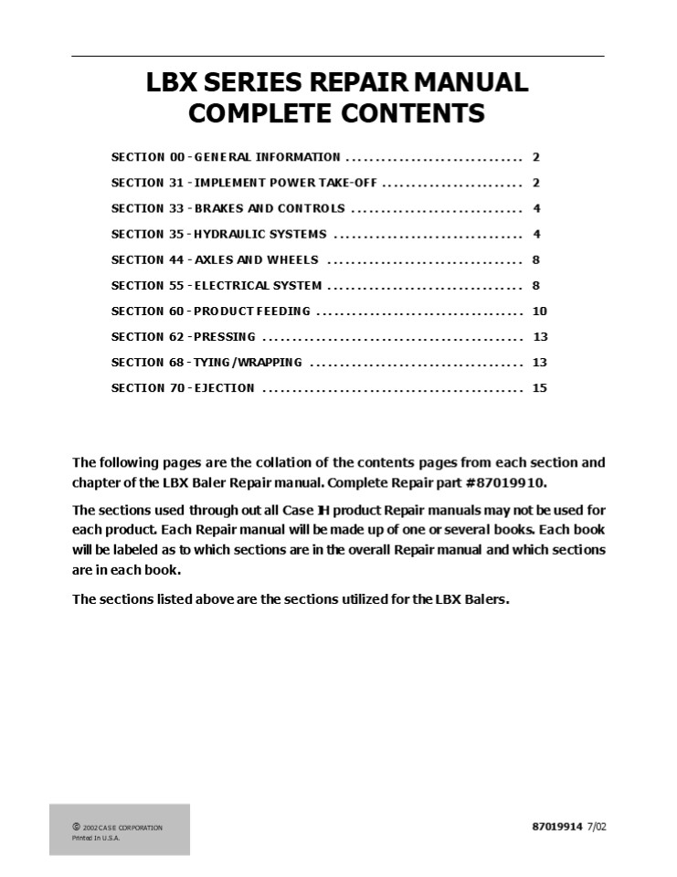
LBX SERIES REPAIR MANUAL COMPLETE CONTENTS
- SECTION 00 - GENERAL INFORMATION
.............................. 2 - SECTION 31 - IMPLEMENT POWER TAKE-OFF
........................ 2 - SECTION 33 - BRAKES AND CONTROLS
............................. 4 - SECTION 35 - HYDRAULIC SYSTEMS ...................
............. 4 - SECTION 44 - AXLES AND WHEELS ...................
.............. 8 - SECTION 55 - ELECTRICAL SYSTEM ...................
.............. 8 - SECTION 60 - PRODUCT FEEDING .....................
.............. 10 - SECTION 62 - PRESSING ............................
................ 13 - SECTION 68 - TYING/WRAPPING ......................
.............. 13 - SECTION 70 - EJECTION ............................
................ 15
The following pages are the collation of the
contents pages from each section and chapter of
the LBX Baler Repair manual. Complete Repair part
87019910. The sections used through out all
Case IH product Repair manuals may not be used
for each product. Each Repair manual will be made
up of one or several books. Each book will be
labeled as to which sections are in the overall
Repair manual and which sections are in each
book. The sections listed above are the sections
utilized for the LBX Balers.
? 2002 CASE CORPORATION Printed In U.S.A.
87019914 7/02
2
SECTION 00 - GENERAL INFORMATION BOOK 1 -
87019911 Chapter 1 - General Information CONTENTS
Description Page Introduction ...................
..................................................
............. 2 Important information
..................................................
....................... 2 General instructions
..................................................
........................ 3 Spare parts
..................................................
................................ 4 Safety
regulations ......................................
......................................
5 Explanation of machine serial numbers
..................................................
........ 8 Units of measure - conversion chart
..................................................
.......... 9 Minimum hardware tightening torques
..................................................
....... 10 General features .....................
..................................................
.... 12 Lubrication schedule ....................
..................................................
.. 19
SECTION 31 - IMPLEMENT POWER TAKE-OFF BOOK 1 -
87019911 Chapter 1 - P.T.O. Drive
Shaft CONTENTS Description Page P.t.o. drive
shaft ............................................
.................................. 2 Bondioli
p.t.o. drive shaft ..............................
........................................
2 Walterscheid p.t.o. driveshaft
..................................................
................. 6 CV U-joint ...................
..................................................
............ 12 Standard U-Joint
..................................................
......................... 14 Center support
bearing replacement ..............................
............................ 16 Flywheel slip
clutch ...........................................
.............................. 18
2
3
SECTION 31 - IMPLEMENT POWER TAKE-OFF BOOK 1 -
87019911 Chapter 2 - Flywheel CONTENTS Descriptio
n Page Flywheel brake adjustment
..................................................
................... 2 Flywheel - Removal -
Installation .....................................
.......................... 2
SECTION 31 - IMPLEMENT POWER TAKE-OFF BOOK 1 -
87019911 Chapter 3 - Main gearbox CONTENTS Descri
ption Page Description and operation
..................................................
.................... 2 Gearbox shafts
..................................................
............................. 2 Specifications
..................................................
.............................. 4 Tightening
torques ..........................................
.................................. 4 Disassembly
of the main gearbox ..............................
................................. 6 Disassembly
of the cranks and upper cover ....................
................................. 6 Disassembly
of the plunger crank drive shaft
..................................................
.. 7 Disassembly of the intermediate shaft
..................................................
...... 10 Disassembly of the stuffer/knotter
drive shaft ......................................
............ 14 Disassembly of the packer/rotor
pick -up drive shaft .............................
............. 17 Disassembly of the input shaft
..................................................
............. 20 Assembly of the main gearbox
..................................................
............. 22 Assembly of the input shaft
..................................................
............... 22 Assembly of the packer/rotor
pick -up drive shaft .............................
................ 26 Assembly of the
stuffer/knotter drive shaft ......................
............................... 29 Assembly of
the intermediate shaft ...........................
................................ 32 Assembly of
the plunger crank drive shaft ....................
................................. 37 Assembly of
the upper cover and cranks .......................
............................... 40 Replacement of
the crank support bearing ........................
............................. 42
3
4
https//www.ebooklibonline.com Hello dear
friend! Thank you very much for reading. Enter
the link into your browser. The full manual is
available for immediate download. https//www.ebo
oklibonline.com
5
SECTION 33 - BRAKES AND CONTROLS BOOK 1 -
87019911 Chapter 1 - Brakes and
controls CONTENTS Description Page Brake shoe -
Removal ..........................................
.............................. 2 Brake control
shaft - Rep. .....................................
................................ 3 Brake shoe -
Installation .....................................
................................. 4 Air brake
valve ............................................
................................... 6 Description
of operation .....................................
................................. 6 Technical
data ............................................
.................................. 8 Disassembly
- assembly .......................................
.............................. 8
SECTION 35 - HYDRAULIC SYSTEMS BOOK 1 -
87019911 Chapter 1 - Bale Density CONTENTS Descri
ption Page Technical data .......................
..................................................
...... 1 Component sketch and location
..................................................
.............. 2 Description and operation
..................................................
.................... 3 Troubleshooting
..................................................
............................ 5 Hydraulic cylinder
- R./I. ..........................................
............................. 6 Set of cylinder
gaskets - Rep. ...................................
............................... 6 Proportional
solenoid valve - R./I. ...........................
................................... 8 Hydraulic
pump - R./I. .....................................
................................... 9
6
SECTION 35 - HYDRAULIC SYSTEMS BOOK 1 -
87019911 Chapter 2 - Pick-up Lifting CONTENTS Des
cription Page Technical data ....................
..................................................
......... 1 Component location
..................................................
........................ 2 Operation
..................................................
................................. 2 Hydraulic
cylinder - R./I. .................................
...................................... 3 Set of
cylinder gaskets - Rep. ..........................
........................................ 4
SECTION 35 - HYDRAULIC SYSTEMS BOOK 1 -
87019911 Chapter 3 - Blade Control CONTENTS Descr
iption Page Technical data ......................
..................................................
....... 1 Description, operation and hydraulic
sketch for blade control .........................
............... 2 Description, operation and
hydraulic sketch for control of blades with rotor
........................... 3 Hydraulic
cylinders - R./I. ................................
...................................... 6 Set of
hydraulic cylinder gaskets - Rep.
..................................................
....... 7
7
SECTION 35 - HYDRAULIC SYSTEMS BOOK 1 -
87019911 Chapter 4 - Bale Ejector - Chute
Positioning - Rear Wheel Locking CONTENTS Descript
ion Page Technical data .........................
..................................................
.... 1 Hydraulic circuit sketches
..................................................
.................... 2 Operation
..................................................
.................................
3 Troubleshooting ................................
..............................................
7 Bale ejector and chute closing control valve -
R./I. ............................................
.... 8 Pressure limiting valve - R./I.
..................................................
................ 9 Uni -directional valve - R./I.
..................................................
.................. 9 Uni -directional flow rate
reducer - R./I. ..................................
...................... 10 Hydraulic cylinders -
R./I. ............................................
........................ 11 Set of cylinder
gaskets - Rep. ...................................
............................. 12
SECTION 35 - HYDRAULIC SYSTEMS BOOK 1 -
87019911 Chapter 5 - The LINCOLN Centralised
Greasing System Models LBX331, LBX421 and LBX431
from Serial number 4238gt CONTENTS Description Page
Specifications ..................................
..............................................
1 Tightening Torques .............................
..............................................
2 Tooling ........................................
..............................................
2 Grease points .................................
..............................................
3 Manual - Centralised Greasing System
..................................................
...... 5 System Component Overview
..................................................
................ 6 System Operation
..................................................
.......................... 8 Grease Outputs and
Dispensing .......................................
....................... 10 Divider Outputs
..................................................
.......................... 20
8
SECTION 35 - HYDRAULIC SYSTEMS BOOK 1 -
87019911 Chapter 5 - The LINCOLN Centralised
Greasing System Models LBX331, LBX421 and LBX431
from Serial number 4238gt (Continued) CONTENTS Desc
ription Page Automatic - Centralised Greasing
System ..........................................
........ 38 Grease Reservoir Filling
..................................................
................... 40 System Operation
..................................................
........................ 41 Divider Outputs
..................................................
.......................... 44 Circuit Diagrams
(all models) .....................................
............................ 48 General Notes
..................................................
........................... 56 Fault Finding
..................................................
............................ 57 Maintenance and
Overhaul .........................................
......................... 61 Tubing and
connectors .......................................
............................... 63 General
Grease Points ...................................
.................................. 67
SECTION 35 - HYDRAULIC SYSTEMS BOOK 1 -
87019911 Chapter 6 - Oiler System CONTENTS Descri
ption Page General Information ...................
..................................................
...... 2 Integrated Automatic Oiler
..................................................
................... 2 Oil Filter Replacement
..................................................
....................... 4 Main Drive Gearbox
..................................................
........................ 4 Stuffer Drive Gearbox
..................................................
....................... 5 Knotter Drive Gearbox
..................................................
...................... 6 Lubrication Guide
..................................................
........................... 7
9
SECTION 44 - AXLES AND WHEELS BOOK 2 -
87019912 Chapter 1 - Axles and
Wheels CONTENTS Description Page Specifications
..................................................
.............................. 1 Description of
Operation ........................................
............................... 3 Sectional Views
.................................................
............................. 4 Tire and Wheel
..................................................
............................. 5 Wheel Hub and
Bearing ..........................................
............................. 6
SECTION 55 - ELECTRICAL SYSTEM BOOK 2 -
87019912 Chapter 1 - General CONTENTS Description
Page General characteristics ....................
..................................................
.. 2 Component discription / Location
..................................................
............ 2 Printed circuits
..................................................
............................ 2 Sensors
..................................................
.................................. 3 Lighting
..................................................
.................................. 6 Fuses and
relays ...........................................
................................. 7 Motors
..................................................
................................... 8 Switches
..................................................
................................. 8 Solenoids
..................................................
................................ 8 Harnesses and
connections ......................................
.............................. 9 General
information ......................................
.................................... 9 Symbols
..................................................
............................... 10 Connectors
..................................................
............................. 14 Connector
location ........................................
................................ 18
10
SECTION 55 - ELECTRICAL SYSTEM BOOK 2 -
87019912 Chapter 2 - Wiring Diagrams CONTENTS Des
cription Page Electrical diagrams - Overview
..................................................
............... 2 List of symbols and where to
find them ........................................
.................. 6 Electrical diagrams
..................................................
....................... 14 SECTION 55 -
ELECTRICAL SYSTEM BOOK 2 - 87019912 Chapter 3 -
Troubleshooting CONTENTS Description Page Descript
ion of operation .................................
......................................
2 Performance monitor - Basic functions
..................................................
.... 2 Performance monitor - Dealer diagnostics
..................................................
. 2 Dealer diagnostics routine window
..................................................
........ 2 Dealer diagnostics - inputs
..................................................
............... 4 Dealer diagnostics - outputs
..................................................
............. 9 Fault diagnosis
..................................................
.......................... 13 Error code overview
..................................................
..................... 13 Error codes
..................................................
............................ 16 Error description
..................................................
........................ 98
11
SECTION 55 - ELECTRICAL SYSTEM BOOK 2 -
87019912 Chapter 4 - Electronic
modules CONTENTS Description Page Module
replacement / adjustment .........................
..................................... 2 monitor
..................................................
................................ 2 Baler
controller .......................................
.................................... 2 Revs/Min.
Status sensor ....................................
............................... 3 Plunger load
sensor ...........................................
............................ 4 Software updates
..................................................
........................... 8 PDT Software
Download Tool ....................................
.............................. 8
SECTION 60 - PRODUCT FEEDING BOOK 3 -
87019913 Chapter 1 - Pickup CONTENTS Description
Page Specifications ..............................
..................................................
2 Description of Operation ......................
.................................................
3 Pickup Removal and Installation
..................................................
.............. 4 Slip Clutch Repair
..................................................
.......................... 9 Burnishing The Slip
Clutch ...........................................
........................ 13 Driveshaft Bearing
Replacement ......................................
........................ 14 Right Pivot Bearing
Replacement ......................................
....................... 17 Left Pivot Bearing
Replacement .....................................
......................... 19 Auger and Bearing
Replacement .....................................
........................ 19 Gauge Wheel Bearing
Replacement .....................................
..................... 24 Guard Replacement
..................................................
...................... 26 Teeth Replacement
..................................................
....................... 26 Tooth Bar and Tooth
Bar Bearing Replacement ..........................
....................... 27 Cam Bearing
Replacement .....................................
............................. 31 Cam Replacement
..................................................
........................ 35
12
SECTION 60 - PRODUCT FEEDING BOOK 3 -
87019913 Chapter 1 - Pickup (Continued) CONTENTS
Description Page Right Reel Bearing Replacement
..................................................
........... 39 Left Reel Bearing Replacement
..................................................
............. 42 Reel Shaft Replacement
..................................................
................... 45 Cylinder Repair
..................................................
.......................... 50 Height Adjustment
..................................................
....................... 53 Flotation Adjustment
..................................................
...................... 53 Tine Repair
..................................................
.............................. 55 Windguard
Height Adjustment ................................
................................ 55
SECTION 60 - PRODUCT FEEDING BOOK 3 -
87019913 Chapter 2 - Packer CONTENTS Description
Page Specifications ..............................
..................................................
2 Description of Operation ......................
.................................................
2 Troubleshooting ................................
..............................................
5 Packer Slip Clutch Replacement
..................................................
.............. 6 Packer Fork Bearing Removal and
Installation .....................................
............... 8 Packer Shaft Bearing Removal
and Installation .................................
................ 12
13
SECTION 60 - PRODUCT FEEDING BOOK 3 -
87019913 Chapter 3 - Stuffer CONTENTS Description
Page Description of Operation ...................
..................................................
.. 2 Troubleshooting .............................
.................................................
6 Stuffer Gearbox Repair .........................
...............................................
8 Holding Fingers Replacement ....................
............................................
33 Stuffer Clutch Repair .........................
...............................................
37 Stuffer Brake Repair ..........................
..............................................
41 Stuffer Shaft Replacement .....................
..............................................
47 Trip Mechanism Repair .........................
.............................................
55 Stuffer Shuttle Feeder Repair
..................................................
.............. 61 Removable Liner Replacement
..................................................
............. 66
SECTION 60 - PRODUCT FEEDING BOOK 3 -
87019913 Chapter 4 - Rotor CONTENTS Description P
age Specifications ...............................
.................................................
2 Rotor lower drive sprocket replacement
..................................................
........ 2 Rotor bearings replacement
..................................................
.................. 5 Rotor shaft replacement
..................................................
..................... 9 Rotor scraper replacement
..................................................
.................. 11 Knife drawer replacement
..................................................
.................. 12
14
SECTION 62 - PRESSING BOOK 3 - 87019913 Chapter
1 - Plunger and Connecting Rods CONTENTS Descripti
on Page Specifications ...........................
..................................................
... 2 Tightening Torques .........................
..................................................
2 Clearances ... ...............................
...............................................
2 Description of Operation .......................
................................................
2 Plunger R./I. .. ..............................
................................................
3 Front Connecting Rod Bearing Replacement
..................................................
. 17 Rear Connecting Rod Bearing Replacement
..................................................
.. 21 Plunger Vertical Bearing Replacement
..................................................
....... 24 Plunger Horizontal Bearing
Replacement ......................................
................ 29 Knife Clearance
..................................................
.......................... 29 Knife Sharpening
..................................................
......................... 30
SECTION 68 - TYING/WRAPPING BOOK 3 -
87019913 Chapter 1 - Knotter General
Information CONTENTS Description Page Specificatio
ns ...............................................
................................. 2 Description
of Operation .....................................
..................................
2 Troubleshooting ................................
..............................................
3 Knotter Trip Mechanism .........................
............................................
12 Knotter Operation Overview ....................
..............................................
13 Knotter Operation Detail ......................
...............................................
14 Knotter Adjustments ...........................
............................................. 18
15
SECTION 68 - TYING/WRAPPING BOOK 3 -
87019913 Chapter 2 - Knotter Drive CONTENTS Descr
iption Page Knotter Driveshaft Repair
..................................................
.................... 2 Knotter Gearbox Repair
..................................................
..................... 7 Knotter Clutch Cam Lobe
Replacement ......................................
.................. 29 Knotter Clutch Roller and
Arm Replacement ..................................
.................. 30 Knotter Brake R./I.
..................................................
........................ 37
SECTION 68 - TYING/WRAPPING BOOK 3 -
87019913 Chapter 3 - Knotter and Knotter
Stack CONTENTS Description Page Knotter Stack
Repair ...........................................
............................... 2 Knotter Frame
Preload Adjustment ...............................
............................. 31 Pinion Gear
Clearance Adjustment .............................
............................... 33 Knotter Frame
Removal Procedure ...............................
............................ 34 Billhook And Cam
Adjustment .......................................
......................... 35 Knife Arm Scraper
Adjustment And Replacement .......................
........................ 36 Twine Disc Timing
Adjustment .......................................
......................... 37 Twine Holder
Adjustment .......................................
............................. 38 Knotter Frame
Overhaul .........................................
............................ 39
16
Suggest For more complete manuals. Please go to
the home page. https//www.ebooklibonline.com If
the above button click is invalid. Please
download this document first, and then click the
above link to download the complete manual. Thank
you so much for reading
17
SECTION 68 - TYING/WRAPPING BOOK 3 -
87019913 Chapter 4 - Twine System, Needles and
Top Hay Dogs CONTENTS Description Page Needle
Adjustment ......................................
..................................... 2 Needle
Cleaner Installation .............................
.....................................
10 Threading the baler ...........................
...............................................
11 Twine Tension Adjustment ......................
.............................................
16 Top Hay Dogs R./I. ............................
............................................. 17
SECTION 70 - EJECTION BOOK 3 - 87019913 Chapter
1 - Bale Discharge Chute CONTENTS Description Page
Description of Operation ........................
...............................................
2 Plunger Rail R./I. .............................
................................................
2 Side Hay Dogs Replacement ......................
.............................................
3 Density Cylinder Linkage R./I.
..................................................
................ 5 Top Compression Plate R./I.
..................................................
................. 6 Side Compression Plates R./I.
..................................................
................ 7
18
SECTION 70 - EJECTION BOOK 3 - 87019913 Chapter
2 - Bale Ejector CONTENTS Description Page Descrip
tion of Operation ................................
.......................................
2 Sectional View .................................
..............................................
3 Bale Chute - Rear Roller Sensor Actuator
..................................................
...... 3 Ejector Lug R./I. .......................
..................................................
..... 5 Ejector Rail R./I. .......................
..................................................
..... 5
19
https//www.ebooklibonline.com Hello dear
friend! Thank you very much for reading. Enter
the link into your browser. The full manual is
available for immediate download. https//www.ebo
oklibonline.com
Recommended
CrystalGraphics Presentations


