

CASE CK36 CK50 Excavator Service Repair Manual Instant Download PowerPoint PPT Presentation
Title: CASE CK36 CK50 Excavator Service Repair Manual Instant Download
1
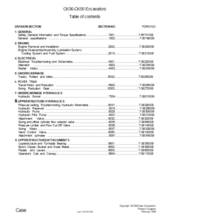
CK36-CK50 Excavators Table of contents DIVISION/SE
CTION SECTION NO FORM NO 1. GENERAL
Safety, General Information and Torque
Specifications ..............................1001.
................................7-55741GB
- General specifications ..........................
..................................,...............
.....1002.................................7-38190G
B - 2. ENGINE
- Engine Removal and Installation
..................................................
..............2002................................
.7-38200GB - Engine Disassembly/Assembly, Lubrication System,
- Cooling System and Fuel System ...................
........................................2010......
...........................7-38210GB - ELECTRICAL
- Electrical Troubleshooting and Schematics.........
........................................4001......
...........................7-38220GB Alternator
..................................................
..................................................
.4002.................................7-38230GB - Starter Motor....................................
..................................................
..........4003.................................7-3
8240GB - UNDERCARRIAGE
- Tracks, Rollers and Idlers........................
..................................................
..5002.................................7-38250GB - POWER TRAIN
- Travel Motor and Reduction ......................
.................................................6
002.................................7-38260GB - Swing Reduction Gear............................
..................................................
...6003.................................7-38270GB - UNDERCARRIAGE HYDRAULICS
- Hydraulic Swivel ................................
..................................................
........7004.................................7-380
10GB - UPPERSTRUCTURE HYDRAULICS
- Pressure setting, Troubleshooting, Hydraulic
Schematics ..........................8001.........
........................7-38280GB Hydraulic
Reservoir ........................................
.............................................8010.
................................7-38290GB - Hydraulic Pump ..................................
..................................................
.......8020.................................7-3830
0GB - Hydraulic Pilot Pump .............................
..................................................
....8021.................................7-38310GB
Copyright Oc 1995 Case Corporation Printed in
England February 1995
Case
Lep 7-38181GB
2
Section
1001 SAFETY INSTRUCTIONS, GENERAL INFORMATION AND
TORQUE SPECIFICATIONS
Copyright 0 1991 JI Case Company Printml in
England Noverrer 1991
J I Case
Lep 7-5574d
3
1001-3
SAFETY
This symbol means ATTENTION ! BEcoaE ALEnz ! roun
sAmzr IS INVOLVED. The message that follows the
symbol coritains imparlaztt infoanafion about
safety. Carefully read he message, MaKe sure you
fully M77D97'sIand Ifie causes of possible injury
or death.
To prevent injury always follow the Warning,
Caution and Danger notes in this section and
throughout the manual. Put the warning tag shown
below on the key for the keyswitch when servicing
or repairing the machine. One warning tag is
supplied with each machine. Additional tags Part
Number 331-4614 are available from your service
parts supplier.
Before slanting enpino, sfudy Operator's Manuat
safety messages. Read atl safety sipns on
machine. Clear fhe area of other persons. Learn
and practise safe use of controls before
operating. It is your responsibility to
understand and follow manufacturers instrucnons
on machine operation, service, and fa observe
pertinent law's and regulations. Operator's and
Service Manuals maybe obtained from your J.I.
CASE dealer.
If you urear clothing that is too loose or do not
use ffie correct safety equipment for your job,
you can be injured. Alw'ays near clothing that
i'ill not catch on obje Exa safety equ"pment
that can be required includes hard hal, safety
shoes, ear protection, eye or face protection,
heavy gloves and reflector ctothinp.
See Other Side
When working in the area of Ihe fan belt '"ith
the engine running, avoid loose Nothing possible,
and use extreme cauâon.
B004
Read its operator's manual to familiarize yourself wiifi the correct control functions.
Operate /he machine and equipment controls from the seatposilion only. Any ofher mefhod could result in serious injury.
When doing checM and tests on the equipment
hydraulics, follow fhe procedures as they are
written. DO NOT chanpe the procedure.
Wfien putting the hydraulic cylinders on
ffis machine through the necessary cyctes to
check operation or to remove air from a circui
make sure all people are out of the
This is a one man machine, no rîdars allowed.
Issued 11-91
Printed in England
Lep 7-55741
4
https//www.ebooklibonline.com Hello dear
friend! Thank you very much for reading. Enter
the link into your browser. The full manual is
available for immediate download. https//www.ebo
oklibonline.com
5
- f 00L
, - a'š àà, 3B " 8
a O O Ø
,.g",s
Ä
R "'
emm
6
1001-5
GENERAL INFORMATION SEAL RINGS, O RINGS AND FLAT
SEALS
CLEANING
Clean all metal components, except bearings, with
steam or white spirit. Do not use caustic soda
when steam-cleaning. After cleaning, dry and oil
the components. Clean oil lines with compressed
air. Clean bearings in kerosene, dry them
completely and oil them.
Always install new seal rings, O-rings and flat
seals, if removed. Lubricate seal rings and
O-rings with petroleum jelly.
SHAFTS
Check all shafts showing signs of damage or wear.
Check particularly to make sure that any surface
of the shaft in contact with bearings or seal
rings is not damaged.
INSPECTIONS
Carefully examine all disassembled components.
Replace all parts showing signs of wear or damage.
Light scores and scratches can be removed by
honing or with a buffing compound. Fast, abnormal
wear of components can be avoided by careful
examination and early detection of wear and
pitting.
SERVICE PARTS
Always use genuine CASE service parts. To order
service parts, see the Spare Parts Catalog and
remember to give the correct reference of the
necessary CASE part. No warranty claims will be
considered for failures involving parts which are
not of CASE origin.
BEARINGS
Check that bearings run freely. Replace bearings
that show signs of too much play or seizing.
Clean bearings in a good solvent or kerosene and
allow them to dry
LUBRICATION
naturally. DO NOT DRY BEARINGS WITH
COMPRESSED AIR.
Never use oil or grease which is different from
that specified in the Operator's Manual or the
Service Manual. No warranty claims will be
considered for failures due to the use of wrong
oil or grease.
NEEDLE BEARINGS
Before installing needle bearings in their
housing, remove any metal edges inside or around
the housing. When installing bearings with a
hydraulic press, grease the inside and the
outside of the bearing with petroleum
jelly. GEARS Check all gears for signs of damage
or wear. Replace damaged or wom gears.
Lep 7-55741
Issued 11-91
Printwl in England
7
STANDARD FASTENER TORQUE SPECIFICATIONS Unless
otherwise specified, use the following torque
specifications. Lubricate the threads with engine
oil or ordinary grease.
SCREWS STANDARD SIZE
M6 7.8 to 9.3 Nm (5.75 to 6.86 lb ft) 9.8 to 11.3 Nm (7.23 to 8.33 lb ft) 12.3 to 14.2 Nm (9.07 to 10.47 lb ft)
M8 17.7 to 20.6 Nm (13.0 to 15.2 lb ft) 23.5 to 27.5 Nm (17.34 to 20.29 lb ft) 29.4 to 34.3 Nm (21.6 to 25.31 lb ft)
id10 39.2 to 45.1 Nm (28.9 to 33.28 lb ft) 48,0 to 55.9 Nm (35.42 to 41.25 lb ft) 60.8 to 70.6 Nm (44.8 to 52.10 lb ft)
M12 62.8 to 72.6 Nm (46.3 to 53.5 lb ft) 77.5 to 90.2 Mm (57.19 to 66.56 lb ft) 103.0 to 117.7 Nm (76.0 to 86.86 lb ft)
M14 107.9 to 125.5 Nm (79.6 to 92.6 lb ft) 123.6 to 147.1 Nm (91.2 to 108.5 lb ft) 166.7 to 196.1 Nm (123.0 to 144.7 lb ft)
M16 166.7 to 191.2 Nm (123.0 to 141.0 lb ft) 196.1 to 225.6 Nm (144.7 to 166.49 lb ft) 259.9 to 304.0 Nm (191.8 to 224.3 lb ft)
M18 245.2 to 284.4 Nm (180.9 to 209.88 lb ft) 274.6 to 318.7 Nm (202.6 to 235.2 lb ft) 343.2 to 402.1 Nm (253.2 to 296.74 lb ft)
M20 333.4 to 393.2 Nm (246.0 to 289.44 lb ft) 367.7 to 431.5 Nm (271.36 to 318.44 lb ft) 490.3 to 568.8 Nm (361.8 to 419.77 lb ft)
Lep 7-55741
Issued 11-91
Printecl in England
8
Section
2002 ENGINE REMOVAL AND INSTALLATION
Copyright O t992 JI Case Company Printed in
England Decerrer 19S2
J I Case
Lep7-082OOE
9
2002-3
Removal and Installation STEP 1
STEP 5
Park the machine on hard level ground. Lower the
attachment to the ground. Release pressure in the
hydraulic circuits and stop the engine. STEP
2 Disconnect the battery, negative (-) terminal
first.
Remove the Hydraulic Oil Reservoir, refer to
Section 8010.
STEP 6
NOTE For installation, install and tighten the
positive () terminal first. STEP 3 Remove the
Cab or Canopy, refer to Section 9004. STEP 4 Put
a container with a capacity of a least 8 litres
under the radiator drain valve (1) and drain the
coolant. NOTE For Installation, install coolant
to the correct /eve/. STEP 7
Remove the bolts (1) and the protector (2). NOTE
For Installation, apply Loctite 271 to the
bolts and tighten to a torque of MU - 77 to 90
Nm M16 - 166 to 197 Nm Remove the hood mounting
bolts (1) from the inside of the engine
compartment.
NOTE
For Installation, apply Loctite 271 to the
bolts (1) and lighten to a torque of M10 - 48 to
56 Nm M12 - 77 to 90 Nm
Lep 7-38200E
Issued 12-92
Printed in England
10
20D2-4 STEP 8
STEP 10 Remove the battery and the fluid level
sensor. STEP 11
Remove the bolts (2) and stide the forwards. STEP
9
box (1)
disconnect and cap the radiator hoses (1) and
(2). STEP 12
Disconnect and remove the gas strut (1) on the
hood. Support the hood on suitable lifting
equipment. Remove the hood.
disconnect ano cap me oil cooler hoses (1) ano
radiator return hose (2). STEP 13
Remove the radiator/oil cooler assembly.
NOTE
For Installation, make sure the radiator(1) and
tan (2) have the following clearances A 30 mm
or more B 15 mm or more C - 20 mm or
more Issued 12-92 Printed in England
NOTE When the hood (1) is dosed make sure t/ie
catch (2) comes in ctose contact with the bracket
(4). When opening the hood (1) make sure the
catch (2) easily comes off the bracket(4), if
necessary adjust with shims (5). Lep 7-d8200E
11
2002-5
STEP 14
STEP 17
Disconnect the throttle cable (1), tachometer
cable (2), fuel hose (3) and clamp (4). NOTE
For Installaäon, refer to fiecfion 9003 for
throtäe cable adjustment.
Disconnect and cap the hoses (1) and (2) from the
hydraulic pump.
STEP 18
STEP 15
Support the engine on suitable lifting equipment.
Remove the engine mounting bolts (1).
Remove the œver next to the right œntrol lever
stand. Disconnect the main electrical hamess from
the engine.
NOTE
For lnstallafion, appty Locfite 2T1 to the engine
mounting bolts and fighten to a torque of M10 -
48 to 56/\/m M12 - 77 to 90 Nm M14 - 124 to 147 Nm
STEP 16
Disconnect and cap the heater hoses (1) (if
equipped).
Lep 7-38200E
Issued 12-92
Printœl in England
12
2002-6 STEP 19
Carefully remove the engine from the
machine. NOTE F-or Installation, follow the
same procedure in reverse order. Open the heater
ya/ye, situated on top of the engine, to atlow
the coolant to circulate. fitart and run the
engine for approximately 5 minutes. Stop the
engine and cheok the coolant level, engine oil
level and hydraulic oil level. Add coolant or oil
if necessary.
Never run an engine in a closed building. is
required under all
Lep 7-38200d
Issued 12-92
Printed in England
13
Section
2010 ENGINE DISASSEMBLY/ASSEMBLY, LUBRICATION
SYSTEM COOLING SYSTEM AND FUEL SYSTEM
Gopyright O 1992 JI Case Company Printed in
England Decerrer 1992
J I Case
Lep 7-38210E
14
2010-2 TABLE OF CONTENTS SPECIFICATIONS...........
..................................................
..................................................
..............................................3 SP
ECIAL TORQUES.....................................
..................................................
..................................................
................6 SPECIAL TOOLS...................
..................................................
..................................................
.......................................6 SHOP
EQUIPMENT TOOLS...................................
..................................................
..................................................
......6 CYLINDER HEAD Removal and
Installation......................................
..................................................
..................................................
.....7 Disassembly and Assembly...................
..................................................
..................................................
...................8 Inspection and
Adustments........................................
..................................................
.................................................9
TIMING GEAR AND CAMSHAFT Disassembly and
Assembly..........................................
..................................................
............................................13 Ins
pection...........................................
..................................................
..................................................
.....................16 PISTONS, CONRODS AND
CRANKSHAFT Disassembly and Assembly...............
..................................................
..................................................
.....................17 Inspection................
..................................................
..................................................
................................................20
CYLINDER BLOCK Inspection........................
..................................................
..................................................
........................................26 LUBRIGA
TION SYSTEM Checking Engine Oil
Pressure..........................................
..................................................
........................................2? Oil
Pump Inspection...................................
..................................................
..................................................
.............27 COOLING SYSTEM Inspection.........
..................................................
..................................................
..................................................
.....29 Water Pump Disassembly and
Assembly..........................................
..................................................
........................................30 FUEL
SYSTEM Fuel Injectors Removal and
Installation......................................
..................................................
................................................31
Disassembly and Assembly.........................
..................................................
..................................................
.......31 Inspection..............................
..................................................
..................................................
..............................31 Pump Element
Valve Sealing.....................................
..................................................
..............................................32 D
elivery Valve Sealing.............................
..................................................
..................................................
...............33 Checking and Adjusting
Injection Pump Timing.............................
..................................................
..........................33 TROUBLESHOOTING......
..................................................
..................................................
...........................................35
This symbol is used throughout this manual to
draw attention to important safety messages.
Whenever you see this symbol, carefully read the
message that follows, since it warns of a risi
of serious injury.
Lep 7-38210E
Issued 12-92
Printed in England
15
2010-3
SPECIFICATIONS General CK36 Make and
Model.............................................
..................................................
................................KUBOTA
V1902BH-5 Type....................................
..................................................
..................................................
...4 Cylinder, 4 Stroke Cycle
Horsepower
SAE...............................................
..................................................
...........................36.6HP (27.3
kW) DIN...........................................
..................................................
...................................33 HP (23.3 kW)
Firing Order....................................
..................................................
..................................................
......................1-3-4-2 Piston
Displacement......................................
..................................................
..................................................
...1861 cm Rated Engine Speed...................
..................................................
..................................................
.....................2670 rpm Engine Idle
Speed.............................................
..................................................
........................................1000-1200
rpm Engine Oil Capacity...........................
..................................................
..................................................
...............7.5 Litres General CK50 Make and
Model.............................................
..................................................
................................KUBOTA
V1902BH-6 Type....................................
..................................................
..................................................
...4 Cylinder, 4 Stroke Cycle
Horsepower
SAE...............................................
..................................................
...........................42.7 HP (31.8
kW) DIN...........................................
..................................................
...................................39 HP (28.7 kW)
Firing Order....................................
..................................................
..................................................
......................1-3-4-2 Piston
Displacement......................................
..................................................
..................................................
...1861 cm Ratged Engine Speed..................
..................................................
..................................................
....................3000 rpm Engine Idle
Speed.............................................
..................................................
........................................1000-1200
rpm Engine Oil Capacity..........................
..................................................
..................................................
................7.5 Litres NOTE The following
specifications are common to CK36 and CK50
Excavators. General Bore and Stroke...............
..................................................
..................................................
............................85 x 82
mm Compression Ration.............................
..................................................
..................................................
....................211 Valve Clearance
(Cold)............................................
..................................................
...............................0.18 to 0.22
mm Direction of Rotation..........................
..................................................
.............Counterclockwise (Viewed from
Flywheel) Pistons Rings per Piston................
..................................................
..................................................
............................................3 Numb
er of Compression Rings...........................
..................................................
..................................................
..........2 Number of Oil Rings...................
..................................................
..................................................
...................................1 Main
Bearings NumberofBewings..........................
..................................................
..................................................
.............................5 Type...............
..................................................
..................................................
..............................................Repl
aceable Lubrication System Type...................
..................................................
..................................................
................ForcedLubrication by Pump Oil
Pressure..........................................
..................................................
.............................2.9to 4.4 bar (42.7
to 64 psi) Oil Pump..............................
..................................................
..................................................
..........................Rotor Type Oil
Filter............................................
..................................................
..................................................
.......Gartridge Type
Lep 7-38210E
Issued 12-92
Printed in England
16
2010-4 Fuel System Fuel Injection
Pump..............................................
..................................................
...........................BOSCH K Type Mini Fuel
Injection Pump Timing.............................
..................................................
...............................23 to 25 before
TDC Fuel Injector Opening Pressure................
..................................................
..................137 to 147 bar (1990 to 2130
psi) Cylinder Head Warpage........................
..................................................
..................................................
....................................0.05 mm Top
Clearance.........................................
..................................................
..................................................
.O.7 to 0.9 mm Compression Pressure...............
..................................................
..................................28.4 to 32.4
bar (412 to 469 psi) Minimum......................
..................................................
..................................................
...................22.6 bar (327 psi) Valves
(Inlet and Exhaust) Valve Clearance
(Cold)............................................
..................................................
...............................0.18 to 0.22 mm
Valve Recess Below Cylinder Head..................
..................................................
........1.1 to 1.3 mm (1.6 mm Maximum) Valve Seat
Width.............................................
..................................................
..................................................
....2.1 mm Valve Seat Angle.......................
..................................................
..................................................
................................45 Valve Stem
Diameter..........................................
..................................................
................................7.960 tp 7.975
mm Valve Guide I.D................................
..................................................
..................................................
.8.015 to 8.030 mm Clearance between Valve Stem
and Valve Guide...................................
................0.04 to 0.07 mm (0.1 mm Maximum)
Valve Timing Inlet Valve - Open...................
..................................................
..................................................
...........20 before TDC Inlet Valve -
Closed............................................
..................................................
....................................45 after
BDC Exhaust Valve - Open..........................
..................................................
...............................................50
before BDC Exhaust Valve - Closed................
..................................................
..................................................
........15 after TDC Valve Springs Free
Length............................................
..................................................
...........41.7 to 42.2 mm (41.2 mm
Minimum) Setting Load/Setting Length..............
..................................................
..............................................117.
4 N/35.12 mm Valve Spnng Tilt.....................
..................................................
..................................................
.........................1.0 mm Rocker Arm
Assembly Clearance between Rocker Shaft and
Rocker Arm........................................
...0.018 to 0.070 mm (0.15 mm Maximum) Rocker Arm
Shafts O.D........................................
..................................................
............................13.973 to 13.984
mm Rocker Arm Bushings............................
..................................................
.........................................14.002
to 14.043 mm Rocker Arm I.D Bushless
Type..............................................
..................................................
........14.002to 14.043 mm Camshah Camshaft Lobe
Height Inlet......................................
..................................................
......................................33.36 mm
(33.31 mm Minimum) Exhaust........................
..................................................
..............................................33.3
6 mm (33.31 mm Minimum) Oil Clearance.............
..................................................
.........................................0.05 to
0.091 mm (0.15 mm Maximum) Camshaft Journal
O.D...............................................
..................................................
.....................39.934to 39.950 mm Camshaft
Bearing I.D.......................................
..................................................
................................40.00 to 40.025
mm Camshaft Alignment.............................
..................................................
............................................0.05
mm (Maximum) Gear Backlash........................
..................................................
..........................0.042 to 0.115 mm (0.15
mm Maximum)
Lep 7-3821OE
Issued 12-92
Printed in England
17
2010-5
Piston and Piston Rings P.tt n B
................................................
23.00 to 23.013 mm (I 3 02 o 2Mo1'1 mm Clearance
betweenP ston P nandSmallEnd"Bush
ngs.I.tt...I...tt ..ttt . . .I tt0.014
to'0038"mm (0.15 mm Maximum) Piston Ring
Gap Top Ring and Second Ring......................
..................................................
.......0.30 to 0.45 mm (1.25 mm Maximum) Oil
Ring..............................................
..................................................
..............0.25to 0.45 mm (1.25 mm Maximum)
Clearance between Second Ring and Ring
Groove............... ............................
................................0.093 to 0.120
mm Clearance between Oil Ring and Ring
Groove............................................
........................................0.020 to
O.052 mm Oversizes of Pistons and
Rings.............................................
..................................................
...............................0.5 mm Connecting
Rods Connecting Rod Alignment.....................
..................................................
..............................0.2 mm (0.5 mm
Maximum) Connecting Rod Small End Bushing
I.D...............................................
...........................................23.025
to 23.040 mm Crankshaft Crankshaft
Alignment.........................................
..................................................
...............0.02 mm (0.08 mm Maximum) Oil
Clearance between Crankshaft Journal and Bearing
1...............................0.040 to 0.118 mm
(0.20 mm Maximum) Oil Clearance between
Crankshaft Journal and Bearings
2-3-4-5....................0.040 to 0.104 mm
(0.20 mm Maximum) Crankshaft Journals
O.D...............................................
..................................................
..................51.921 to 51.940 mm Crankshaft
Bearings I.D......................................
..................................................
............................51.980 to 52.025
mm Oil Clearance between Crank Pin and Crank Pin
Bearing................................0.035 to
0.093 mm (0.20 mm Maximum) Crank Pin
O.D...............................................
..................................................
..................................43.959 to
43.975 mm Crank Pin Bearings I.D..................
..................................................
.................................................4
4.010 to 44.052 mm Undersizes of Crank Pin
Bearings..........................................
..................................................
.........0.2 mm and 0.4 mm End Play of
Crankshaft........................................
..................................................
..0.15to 0.31 mm (0.5 mm Maximum) Oversizes of
Grankshaft Side Metal 1.2.........................
..................................................
.....................0.2 mm to 0.4 mm Cylinder
Liner Cylinder Liner I.D..........................
..................................................
................85.0 to 85.022 mm ( 0.15 mm
Maximum) Engine Lubrication System Engine Oil
Pressure..........................................
..................................................
.................2.9 to 4.4 bar (42.7 to 64
psi) Oil Pump Radial between Outer Rotor and Pump
Body..............................................
.....0.11 to 0.19 mm (0.25 mm Maximum) Rotor Lobe
Clearance.........................................
...............................................0.0
4 to 0.13 mm (0.20 mm Maximum) End Clearance
between Rotor and Cover...........................
................................0.105 to 0.150 mm
(0.2 mm Maximum) Cooling System Thermostat Opening
Temperature......................................
..................................................
......................................80.5 to
83.5C Completely Open............................
..................................................
..................................................
....................95C Radiator
Cap...............................................
..................................................
...........................................0.9
bar (12.8 psi) Fan Belt Tension...................
..................................................
..................................................
............7 to 9 mm at 98 N
Lep 7-38210E
Issued 12-92
I?rinted in England
18
2010-6
SPECIAL TORQUES Rocker Cover Nuts.................
..................................................
..........6.9 to 8.8 Nm Rocker Assembly Retaining
Nuts..............................................
.....23.5 to 27.5 Nm Cylinder Head
Bolts.............................................
...........................93.2 to 98.1
Nm Connecting Rod Cap Retaining Bolts
(Non-Flange)..................... 36.3 to 41.2
Nm Connecting Rod Cap Retaining Bolts (Flange
Type)........................44.1 to 49 Nm
Bearing Case to Cylinder Block Bolts (Non-Flange
Type).............63.7 to 68,6 Nm Bearing Case to
Cylinder Block Bolts (Flange Type)................
....68.6 to 73.5 Nm Flywheel Bolts................
..................................................
.............98.1 to 107.9 Nm Bearing Case Bolts
(With Washers)....................................
...........29.4 to 34.3 Nm Bearing Case Bolts
(Flange Type).....................................
............36.3 to 41.2 Nm SPECIAL TOOLS
5.1 to 6.5 lb ft 17.4 to 20.3 lb ft 68.7 to 72.3
lb ft 26.6 to 30.4 lb ft 32.5 to 36.2 lb ft 47 to
50.6 lb ft 50.6 to 54.2 lb ft 72.3 to 79.6 lb
ft 21.7 to 25.3 lb ft 26.8 to 30.4 lb ft
1. CRANKSHAFT SLEEVE INSTALLER CAS 2255 SHOP
EQUIPMENT TOOLS
- I. TORQUE WRE/vcH, OEM 6474 and OEM 7477
- VALVE SPRING COMPRESSOR OEM 6414
- PISTON RING EXPANDER OEM 6266
- SPRING TESTER OEM l282
- PISTON RING COMPRESSOR OEM 6269
- PULLER OEM 4212
- COOLING SYSTEM PRESSURE TESTER OEM 1347
- DEPTH MicROiviETER SAS 10064-IM
- MICROMETER (0 to 25 mm) OEM 1005TM
- MICROMETER (25 to 50 mm) OEM 10058M
- SMALL HOLE GAUGE SET OEM 1023
- l2. DIAL GAUGECAS10066-1AandMAGNETICBASE CAS
10149 - TELESCOPING GAUGE OEM 1015, 1017, 1018, 1019
- CYLINDER BORE GAUGE OEM 10340
Lep 7-38210E
Issued 12-92
Printed in England
19
2010-7
CYLINDER HEAD
Removal and Installation STEP 1
STEP 5
Remove the drain plug and drain the engine oil.
Drain the coolant from the cylinder block. STEP
2 Remove the air filter assembly and
muffler. NOTE For Assembly, install the muffles
gasket with the steel side facing the
muffles. STEP 3 Remove the rocker assembly
retaining nuts and remove the rocker assembly.
Remove the push rods. NOTE For Installation,
tighten the retaining nuts to a torque of 23.5 to
27.5 Nm (17.4 la 0.3 lb It). Insert the push
rods into the tappets securely. STEP 6
14 j g 0
6
3
11
10
2 O.
7
15
O.. .O
.O
O
Remove the rocker cover retaining nuts. Remove
the rocker cover and discard the gasket.
Disconnect, cap and remove the fuel injector
tubes and the leak off hose.
(A)
(B)
O O
O 1
O g
O 16
2 7
o 13
5
J 2
NOTE For Installation, tighten the rocker cover
nuts to a torque of 6.9 to 8.8 Nm (5.1 to 6.5 lb
h).
(A) Gear Case (B) Flywheel Disconnect and cap
the coolant hose from the cylinder head. Remove
the cylinder head retaining bolts (18 to 1).
STEP 4
NOTE For Installation, apply engine oil to each
bolt and tighten the cylinder head bolts in
sequence to a torque of 93.2 to 98.1 Nm (6B.T to
72.3 lb ft). NOTE Re-tighten the cylinder head
bolts after 30 minutes running.
Remove the alternator and fan belt.
NOTE For Installation, tighten the fan belt to
a tension of 7to 9 mm at 6 to T KgF. Lap 7-38210E
Issued 12-92
Printed in England
20
2010-8 STEP 7
Disassembly and Assembly STEP 8
Remove the cylinder head. Remove and discard the
cylinder head gasket, shim and O-ring.
Remove the valve cap (7), use a valve spring
compressor to compress the valve spring and
remove the collets (6). Remove the valve spring
compressor and remove the retainer (4), spring
(3) and seal (5), discard the seal (5). STEP 9
NOTE For Instatlahon, install a new head gasket
and O-ring. Checking Top Clearance
NOTE On Installafion of the cylinder head,
remove a iniemor nozzle holder and carefully
insert a fuse wire. Be carefull not to let the
fuse wire touch the valves. Rota/e the engine by
hand one full revolution. Remove the fuse wire
and measure where the fuse wire is crushed. This
measurement must be 0.T to 0.9 mm. If the
measurement is not within the reference value,
adjust by inserting a shim bet 'een tfie cylinder
head and the gasket.
Remove the tappets from the cylinder block.
NOTE For Assembly, lollow the same procedure in
reverse order.
NOTE For Assembly, lollow the same procedure
in reverse order.
Lep 7-38210d
issued t2-92
Printed in England
21
2010-9
Inspection and Adjustments STEP 1
STEP 2
Warm the engine to working temperature. Stop the
engine and remove the air cleaner, exhaust
muffler and fuel injectors. Install a
compression tester into the cylinder head. Set
the speed control lever in the stop position,
turn the engine over at 200 to 300 rpm using the
starter motor for 5 to 10 seconds. Make a note of
the maximum pressure. Measure each cylinder at
least three times. The compression pressure must
be between 29 to 32 bar (427 to 469 psi). The
pressure must not be below 22 to 24 bar (320 to
352 psi), and the difference in compression
pressure among cylinders should be less that
10. Thoroughly clean the surface of the
cylinder head. Check the cylinder surface for
warpage using a straight edge and feeler gauge in
the positions shown. NOTE II the measurement is
more than 0.05 mm per 100 mm, the cylinder head
must be machined or replaced. IMPORTANT If the
cylinder head has been machined, refer to STEPS 3
and 4 to check the valve recess.
Lep 7-38210E
Issued 12-92
Printed in England
22
2010-10
STEP 3
STEP 4
Install the valve into the cylinder head, and
using a depth micrometer measure the distance
between the surface of the valve and cylinder
head. If the measurement is not within
specification, replace the valve. If the
measurement is still greater than specification,
check the valve seat face and correct if
necessary. Valve recess 0.05 to 0.15 mm (0.4 mm
maximum).
(a)
A
B
lb)
c)
STEP 5
- How to repair the valve seat
- Valve contacting width
- Corrected surface of valve seat
- Uncorrected surface of valve seat
- A-45 cutter B-15 cutter
- C-65 or 75 cutter
Clean the valve seat surface. Measure the width
of the seat using a set of vernier calipers. The
seat width must be 2.1 mm. To correct the
demensions of the valve seat using a valve seat
cutter, follow the steps.
Remove the carbon from the valve guide. Install
the valve into the valve guide, and using a dial
gauge measure the side to side movement, if
the measurement exceeds the allowable limit,
replace the stem guide and valve. Reference Value
0.04 to 0.07 mm Allowable Limit 0.10 mm
- Use a cutter suitable for the valve guide and the
valve seat. (45 dia. 0.3150) - Grind off the front surface of the valve seat by
15, since the seat surface becomes wider than
before. - Grind off the rear surface of the seat using 65
or 75 cutter to finish the seat 0.0827 inches
wide. - Reface the valve.
Lep 7-S8210E
Issued 12-92
Printed in England
23
2010-11
STEP 6
STEP 8
Measure the free length of the valve spring
dimension A". Reference Value 41.7 to 42.2 mm
Allowable Limit 41.2 mm Put a set square
against the valve spring and measure dimension
B". Allowable Limit 1.0 mm
Measure the ID of the rocker arm and the OD of
the rocker shaft, and calculate the oil
clearance. Reference Value 0.018 to 0.070 mm
Allowable Limit 0.15 mm Rocker Arm ID 13.973
to 13.984 mm Rocker Shaft OD 14.002 to 14.043 mm
STEP 9
STEP 7
Install the valve spring into a tester and
compress to a length of 35.15 mm. Measure the
force required to compress the spring. Reference
Value 117.7 N Allowable Limit 100 N
(B)
(A) Valve clearance (B) Timing window With the
engine cold remove the rocker cover and discard
the gasket. Turn the engine over until the 1 TC
or 1.4 TC mark is aligned with the projection in
the timing window and No.1 piston is at
T.D.C. on the compression stroke. Issued
12-92 Printed in England
Lep 7-38210E
24
Suggest If the above button click is invalid.
Please download this document first, and then
click the above link to download the complete
manual. Thank you so much for reading
25
2010-12
STEP 10
Cylinder No. 1 2 3 4
Intake Valve
Exhaust Valve
Check the valve clearances shown in the table
above. The valve clearance must be 0.18 to 0.22
mm, adjust if necessary. Turn the engine through
360.
Cylinder No. 1 2 3 4
Intake Valve
Exhaust Valve
- Gheck the valve clearances shown in the table
above. The valve clearance must be 0.18 to 0.22
mm, adjust if necessary. - Install the rocker cover with a new gasket and
tighten the retaining nuts to a torque of 6.9 to
8.8 Nm (5.1 to - 6.5 lb ft).
- Compression release window cover
- Compression position
- Compression release position
- 0.750 to 1.125 mm
- Remove the decompression adjustment covers from
the rocker cover. Turn the engine until the valve
to be checked is completely closed. Put the
decompression lever in the compression position.
Adjust the valve clearance to zero by means of
the decompression adjusting bolt, then turn
the adjusting bolt in by 1 to 1-1/2 turns and
tighten the lock nut. Repeat the procedure for
the remaining valves then install the adjustment
covers. - NOTE Afier adjustment, turn the crankshafi by
hand and check to see thai the valve and the
piston should not be in contact with each other
because the depression clearance is too small. - Reference value 0.750 to 1.125 mm.
Issued 12-92
Printed in England
Lep 7-38210E
26
https//www.ebooklibonline.com Hello dear
friend! Thank you very much for reading. Enter
the link into your browser. The full manual is
available for immediate download. https//www.ebo
oklibonline.com
Recommended

