
Volvo EC480D L EC480DL Excavator Service Repair Manual Instant Download
Title:
Volvo EC480D L EC480DL Excavator Service Repair Manual Instant Download
Description:
Volvo EC480D L EC480DL Excavator Service Repair Manual Instant Download –
Number of Views:0
Title: Volvo EC480D L EC480DL Excavator Service Repair Manual Instant Download
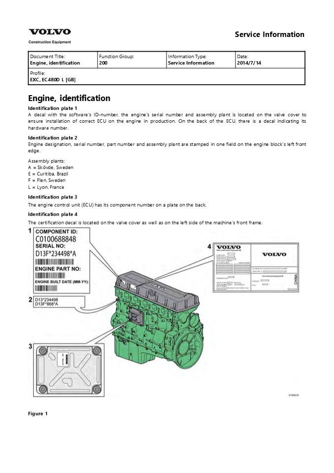
1
Service Information
Document Title Engine, identification Function Group 200 Information Type Service Information Date 2014/7/14
Profile EXC, EC480D L GB Profile EXC, EC480D L GB Profile EXC, EC480D L GB Profile EXC, EC480D L GB
Engine, identification Identification plate 1 A
decal with the software's ID-number, the engine's
serial number and assembly plant is located on
the valve cover to ensure installation of correct
ECU on the engine in production. On the back of
the ECU, there is a decal indicating its hardware
number. Identification plate 2 Engine
designation, serial number, part number and
assembly plant are stamped in one field on the
engine block's left front edge. Assembly
plants A Skövde, Sweden E Curitiba, Brazil F
Flen, Sweden L Lyon, France Identification
plate 3 The engine control unit (ECU) has its
component number on a plate on the
back. Identification plate 4 The certification
decal is located on the valve cover as well as on
the left side of the machine's front frame.
Figure 1
2
Service Information
Document Title Component locations Function Group 200 Information Type Service Information Date 2014/7/14
Profile EXC, EC480D L GB Profile EXC, EC480D L GB Profile EXC, EC480D L GB Profile EXC, EC480D L GB
Component locations
Figure 1 Engine, front side
1 Flywheel housing 7 Engine oil filter
2 P.T.O (Power Take Off) port 8 Oil pan
3 Valve cover 9 EGR cooler
4 Turbocharger 10 Starter motor
5 Turbocharger actuator 11 TDC mark checking port
6 Venturi pipe
3
Figure 2 Engine, back side
12 Fan pulley 20 Crankcase ventilation separator
13 Pre-heating coil 21 Oil level sensor
14 Engine oil filling port 22 Alternator
15 Dipstick gauge 23 Air conditioner compressor
16 Crankcase ventilation tube 24 Air pump
17 Air compressor 25 Air pump belt
18 Fuel feed pump 26 Alternator/Compressor belt
19 E-ECU 27 Fan belt
4
https//www.ebooklibonline.com Hello dear
friend! Thank you very much for reading. Enter
the link into your browser. The full manual is
available for immediate download. https//www.ebo
oklibonline.com
5
Service Information
Document Title E-ECU, MID 128, changing non-programmed ECU Function Group 200 Information Type Service Information Date 2014/7/14
Profile EXC, EC480D L GB Profile EXC, EC480D L GB Profile EXC, EC480D L GB Profile EXC, EC480D L GB
- E-ECU, MID 128, changing non-programmed ECU
- Op nbr 200-068
- Park the machine in the service position A, see
091 Service positions. - Connect the VCADS Pro computer to the machine,
and perform operation '28423-3 MID 128 control
unit, programming'. - When VCADS Pro 'MID 128 ECU, programming' window
appears, follow the instructions for replacing
E-ECU. - Turn OFF battery disconnect switch.
- Remove the engine hood rear cover screws.
Figure 1 1. Screws 6. Remove the bracket.
Figure 2 1. Bracket
6
2. CNEI connector 7. Disconnect the CNEI
connector. 8. Remove the air hose.
Figure 3 9. Remove screws from wire harness
clamps, and disconnect the wiring harness
connectors from E-ECU.
Figure 4 1. Screws 10. Remove screws fixing
the fuel pipe and E-ECU.
Figure 5 1. Screw
7
- Pipe
- Screw
- Put the fuel pipe away.
- Remove 4 screws fixing the E-ECU and replace the
E-ECU. - Install fuel pipe and screws.
- Connect wire harness connectors to the E-ECU, and
install wire harness clamp screws. - Install the air hose and bracket.
- Install the engine hood rear cover, and the
screws. - After replacing E-ECU, press OK button of VCADS
Pro operation '28423-3 MID 128 control unit,
programming'. Now VCADS Pro starts the
programming of software and parameters to the new
E-ECU. - Start the machine and check that no error
messages appear.
8
Service Information
Document Title E-ECU, MID 128, changing pre-programmed ECU Function Group 200 Information Type Service Information Date 2014/7/14
Profile EXC, EC480D L GB Profile EXC, EC480D L GB Profile EXC, EC480D L GB Profile EXC, EC480D L GB
- E-ECU, MID 128, changing pre-programmed ECU
- Op nbr 200-070
- Park the machine in the service position A, see
091 Service positions. - Connect VCADS Pro computer to the machine, and
perform operation '17030-2 Parameter,
programming'. - Use the function 'save all parameters to job
card'. - Turn OFF battery disconnect switch.
- Remove the engine hood rear cover screws.
Figure 1 1. Screws 6. Remove the bracket.
- Figure 2
- Bracket
- CNEI connector
9
- Disconnect the CNEI connector.
- Remove the air hose.
Figure 3 1. Hose 9. Remove screws from wire
harness clamps, and disconnect the wire harness
connectors from E-ECU.
Figure 4 1. Screw 10. Remove screws fixing the
fuel pipe and E-ECU. Put the fuel pipe away.
Figure 5
10
- Screw
- Pipe
- Screw
- Remove 4 screws fixing the E-ECU and replace the
E-ECU. - Install the fuel pipe, and screws.
- Connect wire harness connectors to the E-ECU, and
install wire harness clamp screws. - Install the air hose and bracket.
- Install the engine hood rear cover, and the
screws. - Connect VCADS Pro computer to the machine, and
perform operation 17030-2 Parameter,
programming'. Now the customer parameters are
changed according to the job card saved at step
3. - Start the machine and check that no error
messages appear.
11
Service Information
Document Title Engine characteristic curve Function Group 210 Information Type Service Information Date 2014/7/14
Profile EXC, EC480D L GB Profile EXC, EC480D L GB Profile EXC, EC480D L GB Profile EXC, EC480D L GB
Engine characteristic curve Engine characteristic
curve
Figure 1 Engine characteristic curve, SAE J1349
Gross power
12
Service Information
Document Title Engine, removing Function Group 210 Information Type Service Information Date 2014/7/14
Profile EXC, EC480D L GB Profile EXC, EC480D L GB Profile EXC, EC480D L GB Profile EXC, EC480D L GB
Engine, removing Op nbr 210-070
WARNING
Risk of burns - stop the diesel engine and allow
it to cool down before starting any work.
WARNING
- Removal of residual pressure from the circuit
must be done prior to any maintenance. - NOTE!
- Cable ties and clamps that secure hoses and
electrical wiring must be removed and then
replaced when installing components. - NOTE!
- Disconnected hoses, lines and connections must be
plugged. Oil that drains from hoses, lines and
connections should be collected in a container. - Place the machine in the service position B.
See091 Service positions - Turn off the battery disconnect switch.
- Drain the coolant in a collection container. See
261 Coolant, changing. - Open the engine hood and remove the bracket from
the cowl frame.
Figure 1 1. Bracket 5. Remove the DPF hood,
radiator hood and the rear cover
13
- Figure 2
- DPF hood
- Engine hood
- Engine room rear cover
- Radiator hood
- Remove the engine room cowl frame with the engine
hood using a lifting device. - Disconnect the wire harness connector and the
hoses.
- Figure 3
- Wire harness connector
- Hose
- Remove the expansion tank with the bracket.
- Remove the clamps and then remove the charge air
cooler tube and the radiator hoses.
14
- Figure 4
- Charge air cooler upper tube
- Radiator upper hose
- Radiator breathing hose
- 10. Remove the engine room under covers.
Figure 5 1. Engine room under cover 11.
Release the pressure in the air compressed system
by pushing up a valve on the air tank.
Figure 6 1. Release valve
15
2. Air tank 12. Disconnect the radiator under
hose and remove the charge air cooler under tube.
- Figure 7
- Radiator under hose
- Charge air cooler under tube
- 13. Remove the screws and separate the shroud
from the radiator assembly. Move the shroud to
the engine side.
- Figure 8
- Shroud
- Radiator assembly
- Remove the main pump. See 913 Hydraulic pump,
replacing - Remove pump room covers.
16
Figure 9 1. Pump room cover 16. Disconnect the
hoses, remove the mounting screws and the engine
PTO pump. NOTE! Plug the P.T.O (Power take off)
hole to protect from foreign substances.
- Figure 10
- Hose
- Screw
- Engine PTO pump
- 17. Disconnect the fuel line hoses (4 pcs).
- NOTE!
- Ports must be plugged after disassembling hoses.
Figure 11 1. Hose 18. Disconnect the hose
connected to the air cooler and the compressor
head.
17
- Figure 12
- Compressor head
- Air cooler
- Hose
- Hose
- Hose
- 19. Disconnect hoses connected to the air pump.
- Figure 13
- Air pump
- Hose
- 20. Disconnect the wire-harness connector on the
inlet air sensor.
18
- Figure 14
- Inlet air temperature/pressure sensor
- Connector
- 21. Remove the clamps and the air inlet hose.
Figure 15 1. Turbocharger air inlet hose 22.
Remove the foot step.
Figure 16 23. Remove the clamps and the exhaust
flexible tube.
Figure 17
19
1. Exhaust flexible tube NOTE! Leave the
markings on the tube before removing to remember
the direction of flow direction. 24. Remove the
air conditioner compressor belt and disconnect
the wire harness.
WARNING
Do not disconnect or loosen connections for the
air conditioning unit (AC). Risk of gas leakage.
- Figure 18
- Air conditioner compressor
- Alternator/compressor belt
- Wire harness
- Remove the compressor and lay it down on the
frame. - Disconnect the cab heater hose on the engine
block.
Figure 19 1. Cab heater hose 27. Disconnect
the engine oil remote hoses.
20
Figure 20 1. Engine oil remote hose 28.
Disconnect the starter motor wire harness.
Figure 21 1. Starter motor wire harness 29.
Remove the connectors from the fuel filter and
the water separator.
Figure 22 1. Connector 30. Remove the cover
and the clamps and then disconnect the main wire
harnesses.
21
Suggest If the above button click is invalid.
Please download this document first, and then
click the above link to download the complete
manual. Thank you so much for reading
22
- Figure 23
- Cover
- Clamp
- Wire harness
- 31. Remove the four mounting screws.
Figure 24 32. Lift the engine just a little
using a lifting device, and after confirming
safety around, lift it up and out slowly to the
work stand.
23
https//www.ebooklibonline.com Hello dear
friend! Thank you very much for reading. Enter
the link into your browser. The full manual is
available for immediate download. https//www.ebo
oklibonline.com
Recommended
CrystalGraphics Presentations


