Vapor compression cycle and thermal models in VTB - PowerPoint PPT Presentation
1 / 18
Title:
Vapor compression cycle and thermal models in VTB
Description:
Cross Flow Heat Exchanger ---one fluid unmixed, the other unmixed ... Concentric Tube Heat Exchanger --- Parallel flow. for the case of Cr = 0 or NTU 0.25: ... – PowerPoint PPT presentation
Number of Views:187
Avg rating:3.0/5.0
Title: Vapor compression cycle and thermal models in VTB
1
Vapor compression cycle and thermal models in VTB
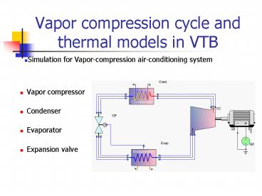
- Simulation for Vapor-compression air-conditioning
system
- Vapor compressor
- Condenser
- Evaporator
- Expansion valve
2
Vapor Compression Cycle
3
Refrigerant R134a Thermodynamic
PropertiesCalculation Subroutines --- Two Phase
Area
(1)Ps(Ts) and Ts(Ps)
Based on the Wagner equation
Where TRT/Tc,PR P/Pc
(2)boiling liquid volume or density v(Ts)
(3)saturated gas volume or density v(Ts) based
on Matin-Hou equation
(4) boiling liquid Enthalpy h(Ts) based on
Clausius-Clapeyron equation
4
Refrigerant R134a Thermodynamic
PropertiesCalculation Subroutines --- Super
Heated Area
Using the modified Benedict-Webb-Rubin equation
of state proposed by McLinden
Using the relevant theory of thermodynamics
(Smith and Van Ness, 1975), The enthalpy is given
by
The entropy in kilojoules per kilogram per degree
Kelvin is
5
Vapor Compressor
(1)
(2)
Under the assumption of isentropic
6
Air Cooled Condenser
Section 1 Desuperheating Section
Section 2 Condensing Section
Where NTU based on condensing area A_cond
Section 3 Subcooling Section
Where A_sub based on sub cooling area
7
Direct Expansion Evaporator
Case 1 Incomplete Evaporation
where
Case 2 Superheated Evaporation
At the boiling section,
Where NTU based on boiling area A_boiling
At the superheated section,
Where A_super based on superheated area
8
Centrifugal Compressor --- for Ideal Gas
(1)
(2)
9
Centrifugal Pump
10
Centrifugal Pump
11
1-Shell and Tube Heat Exchanger
for the case of Cr 0 or NTUlt 0.25
12
n-Shell and Tube Heat Exchanger
for the case of Cr 0 or NTUlt 0.25
13
Cross Flow Heat Exchanger ---fluids unmixed
for the case of Cr 0 or NTUlt 0.25
14
Cross Flow Heat Exchanger ---one fluid
unmixed, the other unmixed
for the case of Cmax mixed, Cmin unmixed
for the case of Cmin mixed, Cmax unmixed
for the case of Cr 0 or NTUlt 0.25
15
Concentric Tube Heat Exchanger ---
Parallel flow
for the case of Cr 0 or NTUlt 0.25
16
Concentric Tube Heat Exchanger --- Counter
Flow
(Crlt1)
(Cr1)
for the case of Cr 0 or NTUlt 0.25
17
Plate-Fin Heat Sink
Heat absorbed by the passing through gas
m1, P1 T1
Heat dissipated from the Heat Sink
m2, P2 T2
T3, Q
where, Q is the array heat dissipation.
Ap is the profile area of the single fin
and equal to . W is the array
width. hb is the heat transfer
coefficient along the inter-fin surfaces
b,L are the geometry parameters as shown in
the figure
18
End


