Geen diatitel - PowerPoint PPT Presentation
1 / 1
Title: Geen diatitel
1
PRE STUDY RESULTS ON HIGH VOLTAGE SOLID-STATE
SWITCHES FOR GYROTRON PROTECTION
A.B. Sterk 1, A.G.A. Verhoeven 1, T. Bonicelli 2,
D. Fasel 3, A. Welleman 4, S. Gekenidis 4 1
FOM-Institute for Plasma Physics Rijnhuizen,
Association EURATOM-FOM, P.O. Box 1207, 3430 BE
Nieuwegein, The Netherlands, Phone 31 30 6096
851, Email sterk_at_rijnh.nl. 2 EFDA-CSU, Max
Planck Institute, Garching, Germany. 3 CRPP,
EPFL, Lausanne, Switzerland. 4 ABB Switzerland
Ltd, Semiconductors, Lenzburg, Switzerland
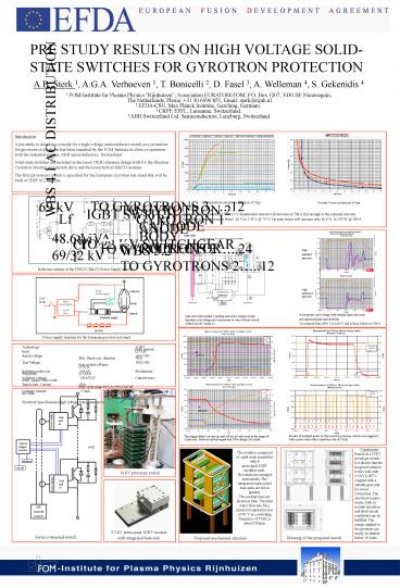
Introduction A pre-study to develop a concept for
a high-voltage semiconductor switch as a
protection for gyrotrons or klystrons has been
launched by the FOM Institute in close
co-operation with the industrial partner, ABB
semiconductors, Switzerland. Solid-state
switches are included in the latest ITER
reference design both for the Electron Cyclotron
Heating and current drive and the lower hybrid
HCD systems. The first (prototype) switch is
specified for the European Gyrotron test stand
that will be built at CRPP in Lausanne.
Desaturation current as function of Vge
On state Vcesat as function of Vge
By decreasing Vge from 15 V to 11 V, desaturation
current will decrease to 700 A (far enough to the
nominal current) Saturation voltage increases
from 1.26 V to 1.33 V _at_ 75 0C On state losses
will increase only by 6 to 135 W _at_ 100 A
With Standard gate unit
Reference scheme of the ITER ECHCD Power Supply
structure
With optimised gate unit
Overcurrent- and voltage with standard gate unit
(top) and optimised gate unit (bottom) Vce
reduced from 2650 V to 1650 V and Ic from 2400A
to 1300 A
Gate unit with counter coupling and active clamp
to limit transient overvoltage and overcurrent
in case of short-circuit of the load (SC mode 2)
Power supply structure for the European gyrotron
test stand
Technology IGBT Peak current limit ? 1
kA Rated voltage 60 kVDC Min. Short-circ.
duration 50 ?s Test Voltage 80 kVDC Fast
switch-off time ? 10 ?s lightning pulse test
110 kV Modulation frequency ? 5 kHz Isolation
voltage 120 kVDC Current wave form square wave
with Rated cont. Current 80A duty cycle
range10 to 90 On/Off Leakage current lt5
mA Operational life time 32.000h Electrical
Specifications High Voltage Solid State Switch
for the gyrotron test stand
Conclusions Based on a 10 kV prototype switch it
is shown that the proposed solution works well
with 2.5 kV IGBTs coupled with a suitable gate
unit for series connection. The electrical
require- ments, both in normal operation and
short circuit conditions can be fulfilled. The
energy applied to the gyrotron can easely be
limited below 10 Joule.
The switch is composed of eight stack assemblies
with 8 press-pack IGBT modules each. The stacks
are arranged horizontally. The integrated
watercooled heat sinks are fed in parallel. The
cooling lines are shown in blue. The total water
flow rate for a junction temperature rise of 50
0C at a switching frequency of 5 kHz is about 250
lpm.
10 kV prototype switch
2.5 kV press-pack IGBT module with integrated
heat sink
Series connected switch
Drawing of the proposed switch
Proposed mechanical structure


