21'4'1Emf, and potential difference, V PowerPoint PPT Presentation
1 / 12
Title: 21'4'1Emf, and potential difference, V
1
21.4 Electromotive force (emf), potential
difference and internal resistance
- 21.4.1 Emf, ? and potential difference, V
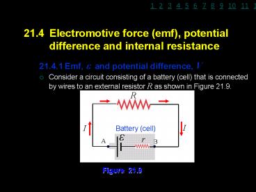
- Consider a circuit consisting of a battery (cell)
that is connected by wires to an external
resistor R as shown in Figure 21.9.
Figure 21.9
2
- A current I flows from the terminal A to the
terminal B. - For the current to flow continuously from
terminal A to B, a source of electromotive force
(e.m.f.), ? is required such as battery to
maintained the potential difference between point
A and point B. - Electromotive force (emf),? is defined as the
energy provided by the source (battery/cell) to
each unit charge that flows through the external
and internal resistances. - Terminal potential difference (voltage), V is
defined as the work done in bringing a unit
(test) charge from the negative to the positive
terminals of the battery through the external
resistance only. - The unit for both e.m.f. and potential difference
are volt (V). - When the current I flows naturally from the
battery there is an internal drop in potential
difference (voltage) equal to Ir. Thus the
terminal potential difference (voltage), V is
given by
3
- then
- Equation (21.9) is valid if the battery (cell)
supplied the current to the circuit where - For the battery without internal resistance or if
no current flows in the circuit (open circuit),
then equation (21.9) can be written as
and
where
4
21.4.2 Internal resistance of a battery, r
- is defined as the resistance of the chemicals
inside the battery (cell) between the
poles and is given by - The value of internal resistance depends on the
type of chemical material in the battery. - The symbol of emf and internal resistance in the
electrical circuit are shown in Figures 21.10a
and 21.10b.
when the cell (battery) is used.
where
OR
Figure 21.10a
Figure 21.10b
5
Example 21.9
A battery has an emf of 9.0 V and an internal
resistance of 6.0 ?. Determine a. the potential
difference across its terminals when it is
supplying a current of 0.50 A, b. the maximum
current which the battery could supply. Solution
a. b.
6
Example 21.10
A car battery has an emf of 12.0 V and an
internal resistance of 1.0 ?. The external
resistor of resistance 5.0 ? is connected in
series with the battery as shown in Figure 21.11.
Determine the reading of the ammeter
and voltmeter if both meters are ideal.
Figure 21.11
2.0 A.
7
21.5 Electrical energy and power
- 21.5.1 Electrical energy, E
- Consider a circuit consisting of a battery that
is connected by wires to an electrical device
(such as a lamp, motor or battery being charged)
as shown in Figure 21.12 where the potential
different across that electrical device is V.
Figure 21.12
8
- A current I flows from the terminal A to the
terminal B, if it flows for time t, the charge Q
which it carries from B to A is given by - Then the work done on this charge Q from B to A
(equal to the electrical energy supplied) is - If the electrical device is passive resistor
(device which convert all the electrical energy
supplied into heat), the heat dissipated H is
given by
OR
9
21.5.2 Power, P
- is defined as the energy liberated per unit time
in the electrical device. - The electrical power P supplied to the electrical
device is given by - When the electric current flows through wire or
passive resistor, hence the potential difference
across it is - then the electrical power can be written as
- It is a scalar quantity and its unit is watts (W).
OR
10
Example 21.11
In Figure 21.13, a battery has an emf of
12 V and an internal resistance of 1.0 ?.
Determine a. the rate of energy transferred to
electrical energy in the battery, b. the rate
of heat dissipated in the battery, c. the amount
of heat loss in the 5.0 ? resistor if the
current flows through it for 20 minutes.
Figure 21.13
11
21.5.3 Combination of cells
- Cells in series
- Consider two cells are connected in series as
shown in Figure 21.14. - The total emf, ? and the total internal
resistance, r are given by
Figure 21.14
and
12
- Cells in parallel
- Consider two equal cells are connected in
parallel as shown in Figure 21.15. - The total emf, ? and the total internal
resistance, r are given by
Figure 21.15
and
If different cells are connected in parallel,
there is no simple formula for the total emf and
the total internal resistance where Kirchhoffs
laws have to be used.

