Heat Sink Optimization PowerPoint PPT Presentation
1 / 10
Title: Heat Sink Optimization
1
Heat Sink Optimization
1
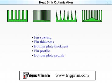
- Fin spacing
- Fin thickness
- Bottom plate thickness
- Fin profile
- Bottom plate profile
2
Two Flow Cases
2
Non confined flow
Confined flow
Non confined flow The incoming air can bypass
the heat sink. The ratio of the channel and the
heat sink cross sections is an important
parameter. Confined flowAll incoming air
penetrates the heat sink.
3
Fin Spacing
3
The thermal performance may or may not improve
when the fin spacing is decreased. There actual
performance depend on the circumstances. Given
air velocity at confined flow The performance
increases. Fan with confined flowDense fin
spacing increases the pressure drop and decreases
air flow rate. There is an optimum fin
spacing. Non confined flowDense fin spacing
increases the bypass flow. There is an optimum
fin spacing.
4
Optimum Fin Spacing for non Confined Flow
4
The optimum fin spacing for non confined flow is
air velocity dependent
5
Optimum fin Thickness for non Confined flow
5
Optimum fin thickness is always a compromise
between two tendencies Thin fins tend to
decrease the fin efficiency. Thick fins tend to
decrease the convection surface and increase the
bypass flow.
6
Optimum Bottom Plate Thickness
6
The bottom plate thickness is only an issue when
there are discreet heat sources. The optimum
thickness is always a compromise between these
two tendencies. Thick bottom plates tend to
spread the heat well but reduce the available fin
height. Thin bottom plates tend to spread the
heat poorly but allow high fins.
7
Calculation Process
7
An optimization is a systematic trial and error
process. Hundreds of calculations are often
needed. The time required for each calculation
is a critical parameter.
8
Fin Profile
8
If the heat transfer coefficient is uniform the
best fin profile is triangular-like shape with
slightly concave sides. A triangular profile is
not far from the best theoretical profile. These
conclusions are not valid if the air gap cross
section considerably deviates from the
rectangular shape. To determine the best fin
profile is a very difficult task. Conventional
heat transfer theory can only be used
exceptionally. There are no important gains
unless the fin efficiency is low (lt50). Well
designed heat sinks usually have fin efficiencies
gt70
9
Bottom Plate Profile
9
To fully optimize the bottom plate of a heat sink
is an extremely difficult problem. The optimum
fin spacing is local and depends on the fin
height. The optimum fin thickness is local and
depends on the fin height. The optimum flow
distribution is not equal velocity in all air
gaps. Sophisticated analyses tools are
needed. Modest gains can be made for extreme
cases.
10
Conclusions
10
Software tools based on conventional heat
transfer theory calculate fast and are therefore
advantageous for optimizing fin spacing, fin
thickness and bottom plate thickness. Sophisticate
d software tools must be used to optimize fin and
bottom plate profiles.

