10' Dynamic Behavior of ClosedLoop Control Systems - PowerPoint PPT Presentation
1 / 26
Title:
10' Dynamic Behavior of ClosedLoop Control Systems
Description:
Alternative form of the standard block diagram. of a feedback control system ... Block diagram for level control system. If a proportional controller is used, ... – PowerPoint PPT presentation
Number of Views:134
Avg rating:3.0/5.0
Title: 10' Dynamic Behavior of ClosedLoop Control Systems
1
10. Dynamic Behavior of Closed-Loop Control
Systems
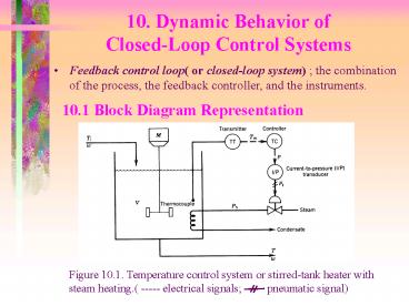
- Feedback control loop( or closed-loop system)
the combination of the process, the feedback
controller, and the instruments.
10.1 Block Diagram Representation
2
10.1.1 Process
Figure 10.2. Inputs and output of the process.
- Dynamic model of a steam-heated, stirred tank
3
- Assume that the dynamics of the heating coil are
negligible since the dynamics are fast compared
to the dynamics of the tank contents. ? Left
side of (10.2) equal to zero!
Substituting (10.4) into (10.1) gives
4
Figure 10.3. Block diagram of the process.
5
10.1.2 Thermocouple and Transmitter
- Assume that the dynamic behavior of the
thermocouple and transmitter can be approximated
by a first-order transfer function
Figure 10.4. Block diagram for the thermocouple
and temperature transmitter.
6
10.1.3 Controller
- Assume that a proportional plus integral
controller is used
Figure 10.5. Block diagram for the controller.
7
10.1.4 Current-to-Pressure(I/P) Transducer
Figure 10.6. Block diagram for the I/P
transducer.
Figure 10.7. Block diagram for the control
valve.
8
- Complete block diagram
Figure 10.8. Block diagram for the entire control
system.
9
10.2 Closed-Loop Transfer Functions
- The standard notations.
10
Figure 10.9. Standard block diagram of a feedback
control system
- In Figure 10.9. each variable is the Laplace
Transform of a deviation variable. - Feedforward path the signal path from to
through blocks , - and .
- Feedback path the signal path from to the
comparator through .
11
Figure 10.10. Alternative form of the standard
block diagram of a feedback control system
12
10.2.1 Block Diagram Reduction
- It is often convenient to combine several blocks
into a single block. - Example
Figure 10.11. Three blocks in series.
13
10.2.2 Set Point Changes( Servo Problem)
Figure 10.9. Standard block diagram of a feedback
control system
- Desired closed-loop transfer function,
14
10.2.2 Load Changes( Regulatory Problem)
- Desired closed-loop transfer function,
15
10.3 Closed-loop Responses of Simple Control
Systems
In this section, we consider the dynamic behavior
of several elementary control problems for load
variable and set-point changes.
- For the liquid-level control system
Figure 10.10. Liquid-level Control System
16
q1 the load variable. q2 the manipulated
variable. Assumption 1. The liquid density r
and the cross-sectional area of the tank A are
constant. 2. The flow-head relation is linear,
q3 h/R. 3. The transmitter and control
valves have negligible dynamics. 4. Pneumatic
instruments are used.
- Mass balance for the tank contents.
- Transfer Function
Where, KP R, t RA
17
Assuming that the dynamics of the level
transmitter and control valve, the corresponding
transfer functions can be written as Gm(s) Km
and Gv(s) Kv .
- Block diagram for level control system
Figure 10.11. Block diagram for level control
system
18
- Proportional Control and Set-Point Change
If a proportional controller is used, then Gc(s)
Kc . The closed-loop transfer function for
set-point changes is given by
where,
KOL is the open-loop gain, KOL Kc Kv Kp Km (KOL
gt 0 for stability ? chapter 11) Thus since t1 lt t
, one consequence of feedback control is that it
enables the controlled process to respond more
quickly than the uncontrolled process. ? The
reason for the introduction of feedback control
19
The closed-loop response to a unit step change of
magnitude M in set point is given by
Figure 10.12. Step response for proportional
control (set-point change)
20
The offset ( steady-state error) is defined as
Since KOL Kc Kv Kp Km Kc ?, KOL ?,
offset ? if Kc ? ?, offset ? 0
21
- Proportional Control and Load Changes
The closed-loop transfer function for load
changes is given by
where,
The closed-loop response to step change of
magnitude M in load
The same situation can be observed as set point
change case
22
- PI Control and Load Changes
The closed-loop transfer function for load change
is given by
This transfer function can be rearranged as a
second-order one.
where, K3 tI / KcKvKm
23
For a unit step change in load,
because of the exponential term in (10.39).
For set-point change, offset will be zero too!
Addition of Integral action ? Elimination of
offset for step changes of load and set-point
24
- PI Control of an Integrating Process
Figure 10.13. Liquid-level control system with
pump in exit line
This system differs from the previous example in
two ways 1. The exit line contains a pump 2. The
manipulated variable is the exit flow rate rather
than an inlet flow rate.
25
The process and load transfer functions are given
by
The closed-loop transfer function for load changes
where, K4 -tI / KcKvKm
KOL KcKvKpKm , Kp - 1/A
26
- The effect of tI
tI ? ?
?
? closed-loop responses less oscillatory
- The effect of Kc
Kc ? ? z4 ? ? closed-loop responses less
oscillatory
- The effect of Kc for the stable process except
the integrating process
Kc ? ? closed-loop responses more oscillatory


