
Nozzle Test : Measurement of Water Jet Movement PowerPoint PPT Presentation
Title: Nozzle Test : Measurement of Water Jet Movement
1
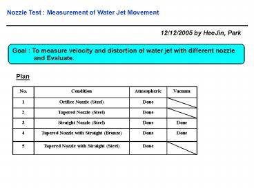
Nozzle Test Measurement of Water Jet Movement
12/12/2005 by HeeJin, Park
Goal To measure velocity and distortion of
water jet with different nozzle and
Evaluate.
Plan
No. Condition Atmospheric Vacuum
1 Orifice Nozzle (Steel) Done
2 Tapered Nozzle (Steel) Done
3 Straight Nozzle (Steel) Done Done
4 Tapered Nozzle with Straight (Bronze) Done Done
5 Tapered Nozzle with Straight (Steel) Done
2
Experimental Sketch (11/16/05 version)
3
Experimental Setup (11/16/05 version)
Front view
Right view
Left view
4
Nozzle Configuration
1)
2)
4)
3)
5)
5
Measuring Environments
High Speed Camera Setting
Measuring Position
Distance from Nozzle Distance from Nozzle
in cm
Front 4 10
Middle 15 37.5
Rear 23 57.5
Total Travel of Jet 27 67.5
Frame Rate(fps) 2500
Exposure Time(µs) 200
Resolution 1280200
6
Measuring Technique
Example Tapered Nozzle with Straight
(atmospheric)
Observing Point
Velocity DistanceFPS
Nozzle Exit
Jet Moving Direction
7
Overall View
Example Tapered Steel Nozzle with Straight
Front
Laminar Flow
Dispersed at Surface
Wave, but no dispersed
Middle
Rear
Break up
Dispersed
8
Overall View
Continuous Captured Frame Image Example Tapered
Steel Nozzle with Straight
Water Jet Flow
Nozzle
9
Result
Breakup Line
Tapered Bronze Nozzle w/ Straight (atmospheric) Tapered Bronze Nozzle w/ Straight (atmospheric) Tapered Bronze Nozzle w/ Straight (atmospheric) Tapered Bronze Nozzle w/ Straight (vacuum) Tapered Bronze Nozzle w/ Straight (vacuum) Tapered Bronze Nozzle w/ Straight (vacuum)
Front Center Rear Front Center Rear
Distance(in)/Frame 0.22 0.2 0.2 0.25 0.25 0.25
Distance(m)/Frame 0.0055 0.005 0.005 0.00625 0.00625 0.00625
Time(s)/Frame 0.0004 0.0004 0.0004 0.0004 0.0004 0.0004
Velocity(m/s) 13.75 12.5 12.5 15.625 15.625 15.625
Distortion Ratio 0.769 1.154 0.769 1.000 1.154 0.769
10
Result
Straight Steel Nozzle (atmospheric) Straight Steel Nozzle (atmospheric) Straight Steel Nozzle (atmospheric) Straight Steel Nozzle (vacuum) Straight Steel Nozzle (vacuum) Straight Steel Nozzle (vacuum)
Front Center Rear Front Center Rear
Distance(in)/Frame 0.2 0.2 0.2 0.25 0.25 0.25
Distance(m)/Frame 0.005 0.005 0.005 0.00625 0.00625 0.00625
Time(s)/Frame 0.0004 0.0004 0.0004 0.0004 0.0004 0.0004
Velocity(m/s) 12.5 12.5 12.5 15.625 15.625 15.625
Distortion Ratio 1.000 0.800 0.600 1.500 1.500 2.000
Tapered Steel Nozzle w/ Straight (atmospheric) Tapered Steel Nozzle w/ Straight (atmospheric) Tapered Steel Nozzle w/ Straight (atmospheric)
Front Center Rear
Distance(in)/Frame 0.18 0.17 0.16
Distance(m)/Frame 0.0045 0.00425 0.004
Time(s)/Frame 0.0004 0.0004 0.0004
Velocity(m/s) 11.25 10.625 10
Distortion Ratio 1.286 1.286 0.571
Tapered Steel Nozzle (atmospheric) Tapered Steel Nozzle (atmospheric) Tapered Steel Nozzle (atmospheric)
Front Center Rear
Distance(in)/Frame 0.2 0.18 0.18
Distance(m)/Frame 0.005 0.0045 0.0045
Time(s)/Frame 0.0004 0.0004 0.0004
Velocity(m/s) 12.5 11.25 11.25
Distortion Ratio 2.500 3.000 3.000
Orifice Nozzle (atmospheric) Orifice Nozzle (atmospheric) Orifice Nozzle (atmospheric)
Front Center Rear
Distance(in)/Frame 0.2 0.18 0.18
Distance(m)/Frame 0.005 0.0045 0.0045
Time(s)/Frame 0.0004 0.0004 0.0004
Velocity(m/s) 12.5 11.25 11.25
Distortion Ratio 2.000 3.000 4.000
11
Further Study Magnetic Field Effect with Jet
Angle
Pulsed Solenoid Magnetic Field (15T)
Transverse Magnetic Field along Hg Jet Axis
Distortion ration w/o Surface Tension
Distortion Ratio along Hg Jet Axis
Distortion ration w/ Surface Tension
12
Further Study
Distortion Ratio of Hg Jet with Surface Tension
Require initial distortion ratio of Hg jet ? Or
Other way to approximate it ?
Mirror Mount Design for Optical Diagnostics
Component Window Clamper , Mirror Adjusting
Mount Requirement Focusing/Tilting of
Reflecting Mirror (3 DOF)
Recommended
