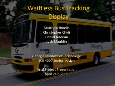
WaitLess Bus Tracking Display PowerPoint PPT Presentation
1 / 18
Title: WaitLess Bus Tracking Display
1
WaitLess Bus TrackingDisplay
- Matthew Brooks
- Christopher Chidi
- Daniel Nadeau
- Josh Mauldin
- Georgia Institute of Technology
- ECE 4007 Senior Design
- Final Project Presentation
- April 24th, 2009
2
Project Overview
- What A display showing GPS locations of Georgia
Tech campus buses using LEDs arranged along a map
placed at campus bus stops. - Why 96 of surveyed students are dissatisfied
with current text based bus prediction systems
which are limited to only a few bus stops. - Who Assists campus pedestrians in deciding
whether to wait for the bus or just walk. - Cost Estimated prototype development cost of
6700. Per unit cost production will be 600.
3
Design Objectives
- Low Power
- Solar panel with battery
- Low power micro-processor
- Internet Access
- Wi-Fi module
- Use existing GPS data available via NextBus.com
(XML feed)? - Self-Sustaining/Easy to Deploy
- No wires/low maintenance
- No energy cost
- Weather proof case
- Low Cost
- Per unit cost 600
4
Design Overview
5
Obstacles and Modifications
Obstacles Solutions
Found that LED leads were not as specified on spec sheet, hence flawing PCB design Soldered jumper wires on the PCB to correct the layout error
RN-111b WiFly module did not support HTTP and therefore could not poll NextBus server Implemented the Nano WiReach module which has support for HTTP and XML data
The serial pin header on the Nano WiReach module was too small to solder wires to Ordered the Molex pin header connector mate and soldered the pins to a breakout board
6
Obstacles and Modifications
Obstacles Solutions
Nano WiReach module failed for unknown reasons Had on hand a spare module, Secure Socket iWiFi, which operates similar to WiReach
ATMega168 processor lacked sufficient onboard memory (16KB) and RAM (1KB) Upgraded to the ATMega328 which has 32KB of memory and 2KB of RAM
Processor uses 5V TTL for serial communication whereas the Wi-Fi module uses 3V, hence could not communicate via serial link Implemented a 5V 3V voltage divider from the processor to module, and a 3V 5V level shifter from module back to the processor
7
PCB Board Design Verification
- PCB board testing and verification
- Corrected LED lead assignments
- Performed diagnostics testing by lighting all
LEDs using I2C commands from the Arduino processor
8
Troubleshooting Visual Display and Aesthetics
- Tested LED visibility after assembly of display
box - Decided to use heat shrink wrap to funnel LED
illumination
9
Serial to Wi-Fi Module Configuration
- Wi-Fi module network connectivity and XML data
collecting - Utilized RealTerm Serial / Telnet software for
module configuration and ATi serial code
debugging
10
Arduino Processor Programming / Debugging
- Microprocessor programming and debugging
- Utilized Arduino C programming platform to code
and debug data communications and parsing
algorithms.
11
Power Supply Testing
- Tested solar panel power supply and battery
supply - Found that the solar panel provides 450 mA of
current in daylight conditions - Original battery supply was faulty, obtained a
new battery
12
Acceptance Testing
- Compared WaitLess display with the NextBus Live
Map - Performed final testing with system as standalone
- Assembled final product with battery and solar
panel attached and positioned system at an actual
bus stop
13
Results
- Product is capable of tracking all buses on all
four routes of the Georgia Tech transportation
service - Current draw of the device at peak operating
conditions is 200 mA which is well below the 450
mA provided by solar panel - Connecting to GTwireless requires external
device authentication through PC - New WPA security features of GT LAWN network will
ease module connectivity - Wi-Fi module sometimes becomes unresponsive after
5-10 minutes of operation - Needs a firmware update
14
Project Demonstration Requirements
- Display the tracking of all buses on at least two
routes of the campus bus service - Demonstrate the sustainability of the product
i.e. solar powered - Demonstrate low current draw / power
- Demonstrate standalone operation running solely
on battery and solar power - Exhibit wireless connectivity and weather
resistance
15
Market / Cost Analysis
Component Labor Hours Labor Cost Equip Cost Total Cost
Arduino Duelmilanove/ ATmega328/V 150 5,250.00 34.95 5284.95
I2C LED Controllers 2 70.00 16.00 86.00
Red, Green, Blue LEDs 10 350.00 33.99 383.99
Serial to Wi-Fi Module 1 35.00 62.90 97.90
Solar Panel 1 35.00 49.95 84.95
Battery 1 35 18.21 53.21
Switching Voltage Regulator 2 70.00 22.00 92.00
Custom PCB 10 350.00 100.00 450.00
External Weather-Proof case 3 105.00 50.00 155.00
TOTAL LABOR 180 6,300
TOTAL PARTS 388.00
PROJECT TOTAL 6,688.00
16
Market / Cost Analysis
Total Project Cost 6,688.00
Physical Value of Product 388.00
of Units Capable of being sold 42 for each bus stop on the GT campus
Estimated Market Value of Product to Break Even 600.00
17
Future Enhancements and Modifications
- Reduce the depth of the display box
- Implement a smaller, more efficient battery
- Solder all electronic components to one PCB
design - Investigate surface mount LED technology
- Place the vinyl map decal inside of transparent
casing to protect it - Implement WPA security login for easier module
connectivity - Expand the design to be used for other
transportation services - Add an LED array panel below the map display to
output text-based arrival time estimations for
each stop
18
Questions?

