
MINERnA PowerPoint PPT Presentation
1 / 12
Title: MINERnA
1
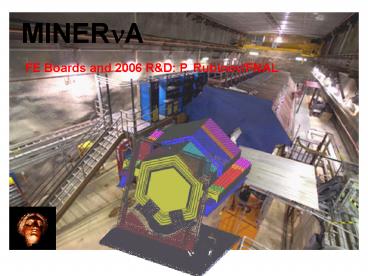
MINERnA
FE Boards and 2006 RD P. Rubinov/FNAL
2
Electronics in MINER?A
- Front-end Electronics
- What we know
- What we need to do next
- DAQ and Slow Control
- What we need
- When we need it
- Power and Rack Protection
- a few words on Low Voltage
- grounding
FE Board
3
Front End board
- 16ch proto FE boards have been used so far
(designed to interface to Alner box) - Seem to work ok.
- Tested LVDS chain scheme (work done by C Gingu)
4
LVDS chain
- LVDS chain implemented by C. Gingu.
- Learn about reliability, latency, phase noise
- These set maximum chain length
- E.g. latency is 113ns per board so need spill
signal at least 113ns121.4ns/foot 1.4uS
before spill
5
CW generator
- Recently assembled prototypes
- 22 stage Cockroft-Walton fed by a resonant
converter - Seem to work ok
- Needs to be tested with PMT tube
6
Next step for FE
- 64ch board designed for Minerva PMT box
- Pick TriP or TriP-t
- Implement bigger FPGA
- Integrate CW generator circuitry
- Implement realistic LV distribution (worry more
about power dissipation)
7
Next step for FE
- Our current plan is
- HV generator is split in two partly in the
base, partly on the FE. - The base carries the actual diode ladder.
- It is designed to fit into the Minerva PMT
box(now things are becoming coupled!) - Design of the base is done and out for quotes.
- I think we can use a butchered up HV prototype to
drive this base. - Notice the LEMO- this connects to the last dynode
8
Next step for FE
9
DAQ
- We need CROC design which will allow for a
realistic readout and control of the next
generation prototype FE. - The CROC is
- 100 digital 6U VME module
- Less complicated than FE but equally important.
- We need it
- to test a full length chain
- have sufficient DAQ bandwidth for PMT testing
10
LV and Grounding
- Stan Orr (Fermilab engineer) has been asked to
help us out with these issues. - Stan is head of the Fermilab Electrical Safety
Subcommittee so we are in very good shape here. - LV distribution philosophy is
- Distribute at 48V (50V is safety threshold) to
minimize current (smaller, simpler cable plant) - Use commercial, off the shelf equipment.
11
LV and Grounding
- Grounding philosophy
- Local reference for every PMT.
- One common safety ground.
- Important point
- Everyone should understand If it conducts, it
is part of the electronics.(no matter what the
WBS code is)
12
Conclusion
- In FY2006 we expect to have
- Second FE prototype, realistic for Minerva
- Qty 20
- PMT base which works with M64 and our boxes
- Qty enough for PMT testing, 40
- CROC module
- Qty 4, at least one fully working needed for
PMT testing.
Recommended
