
In a QUANTUM REGIME an FEL behaves as a TWOLEVEL system - PowerPoint PPT Presentation
1 / 23
Title:
In a QUANTUM REGIME an FEL behaves as a TWOLEVEL system
Description:
Longitudinal Coherence Preservation & Chirp Evolution in a High Gain Laser ... energy chirp Dg/g = 1e-3/100fs. incl. current profile. complete s2e bunch. optics ... – PowerPoint PPT presentation
Number of Views:29
Avg rating:3.0/5.0
Title: In a QUANTUM REGIME an FEL behaves as a TWOLEVEL system
1
Quantum Regime of SASE-FEL
R. Bonifacio (1), N. Piovella (1,2), G.R.M. Robb
(3), A. Schiavi (4) (1) INFN-MI, Milan,
Italy. (2) Dipartimento di Fisica, Univ. of
Milan, Italy (3) SUPA, Dep. of Physics, Univ. of
Strathclyde, Glasgow, UK (4) Dipartimento di
Energetica, Univ. of Rome La Sapienza INFN,
Italy
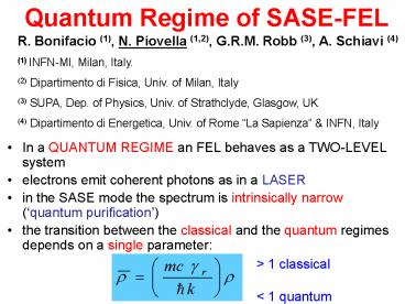
- In a QUANTUM REGIME an FEL behaves as a TWO-LEVEL
system - electrons emit coherent photons as in a LASER
- in the SASE mode the spectrum is intrinsically
narrow (quantum purification) - the transition between the classical and the
quantum regimes depends on a single parameter
gt 1 classical lt 1 quantum
2
Qika Jia (NSRL, Heifei, China)
3
Longitudinal Coherence Preservation Chirp
Evolution in a High Gain Laser Seeded Free
Electron Laser Amplifier
J.B. Murphy, J. Wu, X.J. Wang T. Watanabe, BNL
SLAC
? 10-3? 800 nmTFWHM 1 ps?FWHM 7 nm
4
Evolution of the Moments Numerical Example
5
High-contrast attosecond pulses from X-ray FEL
with an energy-chirped electron beam and a
tapered undulator
- E. Saldin, E. Schneidmiller and M. Yurkov
FLS2006, May 18, 2006
- Energy chirp in SASE FELs
- Energy chirp and undulator taper symmetry and
compensation - An attosecond scheme
- Beyond fundamental limit
6
Beyond fundamental limit
- It was generally accepted that a natural limit
for a pulse duration from SASE FEL is given by
(rw)-1, FEL coherence time (duration of
intensity spike) - But energy chirp undulator taper allow to get
strong frequency chirp (gtgt rw) within a spike
without gain degradation - Use monochromator to select a pulse that is much
shorter than a spike - Contrast remains high spontaneous spectrum from
the rest of the bunch gets broader due to the
stronger taper - Example increase energy modulation by 3 so that
a6. For optimal bandwidth of a monochromator the
reduction factor is (2a)1/2, i.e. pulse duration
is in sub-100 as range.
7
Optical Klystron Enhancement to SASE FEL
Y. Ding, P. Emma, Z. Huang (SLAC), V. Kumar (ANL)
- SASE OK not sensitive to phase mismatch
8
?1.0 Å LCLS possibility with OKs
Parameters of the chicane for delta_E510-5 R56
0.23µm, B0.70T LB6cm, Lchicane51cm
9
Beam Physics Highlights of the FERMI_at_Elettra
Project
S. Di Mitri on behalf of the Accelerator
Optimization Group M. Cornacchia, P. Craievich,
S. Di Mitri, G. Penco, M. Trovo, ST I.
Pogorelov, J. Qiang, M. Venturini, A. Zholents,
LBNL P. Emma, Z. Huang, R. Warnok, J. Wu,
SLAC D. Wang, MIT FLS Workshop, May 2006,
Hamburg
10
Outlook THE ACCELERATOR
1st Chicane
2nd Chicane
RF Photo-injector
L1 and L2 2/3p Travelling Wave Acc. Struct.
L3 and L4 3/4p Backward Travelling Wave Acc.
Struct.
Injector S0A, S0B Acc. Struct.
FEL1
FEL2
E1 220 MeV R56 - 0.03 m c.f. 3.5
E2 600 MeV R56 - 0.02 m c.f. 3.0
E0 100 MeV I 60 A (10ps)
E3 1200 MeV I 800A (700fs) I 500A (1.4ps)
Short bunch
Long bunch
Medium bunch
Bunch length 200 fs (flat part)
700 fs (flat part) 1.4 ps (flat part) Peak
current 800 A 800 A
500 A Emittance(slice) 1.5 mm
1.5 mm 1.5 mm
Energy spread(slice) lt150 keV
lt150 keV lt150 keV Flatness,
d2E/dt2 lt0.8 MeV/ps2 lt0.2
MeV/ps2
DE
S. Di Mitri FLS2006
t
11
E-Beam Physics - REVERSE TRACKING
- Valid for frozen beams
- (see, Appendix)
- It predicts a ramped current
- profile from the Injector.
- Confirmed by the forward
- tracking.
END what we want
BEGINNING what we need
Longit. Wake generated by a PARABOLIC current
distrib.
Longit. Wake generated by a UNIFORM current
distrib.
Longit. Wake generated by a RAMPED current
distrib. linear solution
S. Di Mitri FLS2006
courtesy M. Cornacchia, P.Emma, G. Penco, A.
Zholents
12
Experiences with Start to End Simulations and
Tolerance Studies for HGHG FEL Cascades Bettina
Kuske, Michael Abo-Bakr, Atoosa
Meseck ICFA-FLS-Workshop, Hamburg, May 16th, 2006
13
1. Example Bunches from S2E simulations ltgt
constant bunch parameters
- Single HGHG stage
- 280 MeV, 200 A
- Modulator
- bunching less smooth for s2e bunch
- (energy spread)
- no effect for g-chirp, current
- Radiator
- power loss for every non-constant parameter
- Colour code
- bunch with constant parameters
- incl. energy chirp Dg/g 1e-3/100fs
- incl. current profile
- complete s2e bunch
- optics mismatch
14
Start-To-End Simulations for the European XFEL
Martin Dohlus, Igor Zagorodnov (DESY)
? description of European XFEL beam line ?
technical aspects of simulation
matching / codes / tools ? gun ? µ-bunch
instability laser heater /
technical aspects of simulation ? European XFEL
segmentation (for simulation) ? method 1 (fast) ?
method 2 (reference) ? method 3 (efficient
accurate) to be done
15
method 1
method 2
current slice emittance
16
Single Bunch Emittance Preservation in XFEL Linac
G. Amatuni, R. Brinkmann, W. Decking, V. Tsakanov
DESY, CANDLE
-
-
Booster Linac - Coherent oscillations
- uncorrelated
610-6 210-4 - correlated 210-3
1.210-3 - Cavity Misalignments 510-6
310-7 - Modules Misalignments 410-5
2.510-6 - Correlated Misal. (130o) -
710-6 - Cavity tilts
- uncorrelated 5.810-5
0.6 - correlated 0.6
1.9 - One-to-One correction
- uncorrelated 6.310-5
0.4 - correlated 1.7
2
Total Emittance dilution lt5 with 2 Modules/Cell
17
A Smith-Purcell Backward Wave Oscillator for
Intense Terahertz Radiation
Kwang-Je Kim and Vinit Kumar ANL and The
University of ChicagO
Smith-Purcell Propagating wave
18
Example Parameters
19
Toward Coherent X-raysexploring coherent
emission mechanisms (FEL-like) in Thomson Sources
A.Bacci, M.Ferrario, C. Maroli, V.Petrillo,
L.Serafini Università e Sezione I.N.F.N. di
Milano (Italy) LNF, Frascati (Italy)
20
Production of coherent X-rays with a free
electron laser based on optical wiggler
by C. Maroli et al., (INFN)
First example Laser pulse time duration up to
100 ps, power 40-100 GW, w0100mm,
lL10 mm (CO2 laser),total laser
energy 4-10J, aL00.3,
guided Electron beam Q1-5nC, Lb1mm, focal
radius s025 mm, I0.3-1.5 kA,
energy30 MeV (g060) , transverse normalized
emittance up to 1 mm mrad,
dg/g10-4.
r2.8 10-4 gain length Lg
2.83 mm Radiation lR7.56 Angstrom
ZR2.5 m
5.25 no appreciable
quantum effects
21
Hamburg 15-19 May 2006
10
en0.6 mmmrad at t0, guided laser pulse
- Collective radiation
- 2 1010 Photons
- Incoherent radiation
- 2108 photons
A2sat0.11, saturation length about 7 Lg (70
ps) 2,361010 photons (a) averaged bunching
factor ltbgt in the middle of the bunch vs time,
(b) logarithmic plot of ltA2gt vs time in both
coherent (1) and incoherent (2) cases. w050 mm
with a flat laser profile, aL00.3, Q3 nC, I
0.9 kA,ltggt60, Dpz/pz10-4 , en0.6 , Dw/w
-10-4.
22
- Conclusions
- At the present state of the analysis we may
say that the growth of collective effects during
the back scattering Thomson process is possible
provided that - a low-energy , high-brigthness electron beam is
available - (normalized transverse emittance at t0
preferably less than 1) - the optical laser pulse is long enough to allow
the electron - bunching by the spontaneous (incoherent)
radiation and the - consequent FEL instability
- the laser envelope should have rather flat
transverse and longitudinal - profiles
23
Summary remarks of WG3
- Short-wavelength FELs are on the horizon. More
excitement to come - Start-to-end simulations are invaluable tools to
understand the performance and tolerance of these
machines - Seeding can improve SASEs temporal coherence,
more technical challenges to overcome - Theoretical progress is still made in many areas
- Novel sources based on FEL-like mechanism may
provide compact, coherent THz or X-rays
Recommended
CrystalGraphics Presentations


