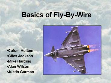
Basics of FlyByWire PowerPoint PPT Presentation
Title: Basics of FlyByWire
1
Basics of Fly-By-Wire
- Colum Holtam
- Giles Jackson
- Mike Harding
- Alan Wilson
- Justin Garman
2
Summary
- History evolution of control system
- Advantages of latest system
- Mechanical systems versus Mechatronic
- Flight control computer - system schematic
- Theoretical overview
- Developments and applications
3
FLY BY WIRE
- The Wright brothers made the first controlled
powered flight on 17th December 1903 - Control surfaces such as ailerons and elevators
- Later came Tailerons and vector thrust
- The old mechanical system for controlling
aircraft worked using pulleys and wires to move
the control surfaces the made the aircraft move
in the three axis (pitch, roll yaw) - As the demand for more performance from the
aircraft increased, the ability of the pilot
(i.e. physical strength) became insufficient
4
Advantages of fly-by-wire
- Carefree handling automatic suppression of
stalling and over-stressing - optimised handling
- agility
- increased performance
- handling of vectored thrust
- reduced drag
- auto pilots
- reduced maintenance
5
Mechanical vs Mechatronic
- Pitch/Roll Stick rudder pedals
- Steel wires and pushrods
- Hydraulic signals
- Artificial Feedback
- Small electronic unit mounted on the pilots
armrest - Electrical wires
- Electrical Impulses
- No force feedback Pitch rate/roll rate
- Analogue e.g Concorde, 1969
- Digital e.g. Airbus A310
- Airbus factor
6
Basic Block Diagram Showing System Schematic
Block Functionality for pitch
7
- A, b, c, d e are suitably located sensors for
providing pitot and static pressures and local
air flow measurements. - Used to derive the precise velocity vector of
the aircraft, that is both in magnitude and
direction. - This data is then used to calculate a suitable
pitch for the aircraft.
8
System Overview of Pitch Control
9
Fly By Wire Control System Overview
10
Applications of Fly-By-Wire
11
The Eurofighter
12
Eurofighter flight controls
13
The future of Fly-By-Wire
14
Summary of Fly-By-Wire
- Allows unstable aircraft to fly
- More reliable and safer than mechanical
controlled aircraft - More agile military aircraft
- Reduced maintenance
- Increased performance and efficiency
15
Thank you
- Questions?
PowerShow.com is a leading presentation sharing website. It has millions of presentations already uploaded and available with 1,000s more being uploaded by its users every day. Whatever your area of interest, here you’ll be able to find and view presentations you’ll love and possibly download. And, best of all, it is completely free and easy to use.
You might even have a presentation you’d like to share with others. If so, just upload it to PowerShow.com. We’ll convert it to an HTML5 slideshow that includes all the media types you’ve already added: audio, video, music, pictures, animations and transition effects. Then you can share it with your target audience as well as PowerShow.com’s millions of monthly visitors. And, again, it’s all free.
About the Developers
PowerShow.com is brought to you by CrystalGraphics, the award-winning developer and market-leading publisher of rich-media enhancement products for presentations. Our product offerings include millions of PowerPoint templates, diagrams, animated 3D characters and more.

