HF status report for Quarknet 2002 PowerPoint PPT Presentation
1 / 20
Title: HF status report for Quarknet 2002
1
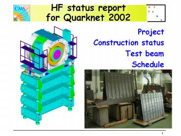
HF status reportfor Quarknet 2002
- Project
- Construction status
- Test beam
- Schedule
2
HF
To cope with high radiation levels (gt1 Grad
accumulated in 10 years) the active part is
Quartz fibers the energy measured through the
Cerenkov light generated by shower
particles. This is the cause of two of the
peculiar features of this calorimeter The
visible energy is carried by relativistic
particles, i.e. electrons the calorimeter is
sensitive to the EM component (p0) of the
hadronic shower. Shower size depends on Moliere
radius not li The light is generated
preferentially at 45 degrees light propagation
is far from usual meridian one.
Iron calorimeter Covers 5 gt h gt 3 Total of
1728 towers, i.e. 2 x 432 towers for EM and HAD
h x f segmentation (0.175 x 0.175)
3
HF responsibility sharing
4
The HF bulding block the wedge
5
Absorber production
Absorbers produced in Snezensk (Russia), control
by ITEP)Moscow) 20/36 wedges produced, 18
delivered at CERN expect all by end 2002. Well
on schedule !
Built out of bricks, made of 5mm Fe plates with
fiber grooves every 5 mm Assembled by diffusion
welding. Bricks are machined and kept together by
welded steel straps Geometry OK (well within
tolerances) checked by templates and verified by
metrology at CERN on a sample of wedges.
6
Strongback and backplane production
- Contract signed with Turkish firm in December
2001. - First 9 strongbacks and 6 backplanes delivered
geometry verified by mounting the first 9 wedges
on a jig simulatingthe geometry of final
shield. - Expect complete delivery
- September 2002
7
Shield Support table
Table production started in IRAN expect 1st
delivery spring 2003 Discussion for production
of Shield and Endplug advanced hope to place
contract with HEPCO (Iran) soon. Aim to have
first one at CERN by summer 2003
8
Pre-assembly of wedgesgeometry verification
Simulate assembly in shield three wedges at a
time in jig simulating the local geometry of the
shield
Dimensional measurement with teodolite system
result is good. No problem for final assembly !
9
Photomultipliers
- Hamamatsu R7525HA 8 dynodes PMTs.
- To operate at gains varying from 105 at low h to
5x10⁴ at high h. - All tubes are tested at Univ. of Iowa
- 500 tubes delivered and tested (2 rejected).
Complete delivery of 2000 tubes by mid 2003
For one tube in every batch Double-pulse
linearity, Gain vs HV for each batch Single
photoelectron spectrum X-Y scan (spatial
uniformity) Lifetime For each tube Pulse
width Pulse rise time Transit time Transit time
spread Anode dark current Relative gain coupled
with cathode sensitivity, Pulse
linearity Quality control decision on each tube.
10
PMTs
11
Read Out Box
2 boxes built plan to use them in Test beam
PM Base PCB
ROBox
12
ROboxes
Ro Box
m-metal shield
Ferrule Plate
13
FIBERS
QP Fibers (Quartz core, Plastic cladding) Fused
silica core, polymer cladding, UV-cured polymer
buffer. 920 km needed N.A. 0.37 /- 0.02 350
Km delivered Expect completion by September 2002
Km Of fiber
June02
Weeks in 2002
14
Fiber stuffing
- Just started (May 2002) on two wedges in Hungary
- From first experience it was decided that the
actual fiber insertion will continue at CERN for
the remaining modules. This is to reduce logistic
and transport overheads and risks of accidents
CERN infrastructure is better suited to handle 6
tons delicate objects. - Fiber cleaving procedures being optimized
commercial Fujikura cleaver adopted. One cleaving
line now will be doubled within weeks cleaving
is the bottleneck. - Fiber bundling procedure shown to work with
largest (gt600 fibers) bundles. No problems in
that area. - Expect the first two stuffed modules by end of
July to expose to H2 Test beam.
15
Fiber stuffing
Started in Hungary
Source tubes insertion
Fiber bundles preparation
16
Fiber stuffing
17
Test beam
- Two wedges assembly (H2 beam)
- Test
- Final PMT-base and ROBOX
- Resolution scan with final geometry
- Crack area between modules
- Containment corrections at high h
- Validation of source calibration
18
Test beam
Crack region scan The distance between fibers
of two adjacent modules vary between 4 and 7 mm
Such dead regions should not pose a problem if
one believes the simulation. One of the goals of
the test beam is to check this.
19
Digital readout
- HF readout is fully integrated into HCAL readout
HF PMTs use the non inverting input of the QIE - Latest generation QIE being produced now in the
US should be fully HF compatible - Aim to integrate final readout starting in fall
2002 for the source testing and light calibration
of the finished wedges - Plan to have Test beam exposure in 2003 with
final readout
20
Schedule
Conclusion HF is well on schedule and stays
clear of CMS critical path

