LED Array with Adam Zysk - PowerPoint PPT Presentation
1 / 23
Title:
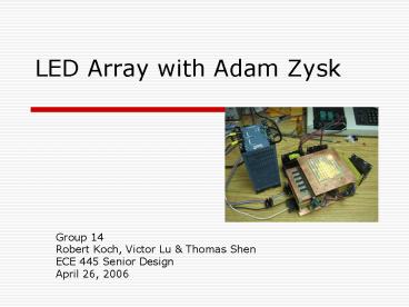
LED Array with Adam Zysk
Description:
PIC program. Windows program. The LED Array System. LED Board. Register Boards. Control Board ... Assembled using solder paste and toaster oven. 400 LEDS in 3 1 ... – PowerPoint PPT presentation
Number of Views:43
Avg rating:3.0/5.0
Title: LED Array with Adam Zysk
1
LED Array with Adam Zysk
- Group 14
- Robert Koch, Victor Lu Thomas Shen
- ECE 445 Senior Design
- April 26, 2006
2
Design Review Specifications
- Purpose
- Research in optical coherence
- Requirements
- 400 SMD Dual Color LEDs
- 3 x 3 layout of LEDs
- Individually controlled LEDs
- GUI and mouse input
3
Revisions to Original Design
- Registers now sink current rather than source
current - Clock signal now buffered rather than driving all
100 registers directly with a single PIC output - Fans added to relieve overheating
4
Final Features
- 400 SMD Red/Green LEDs
- 31/8 x 31/8 area.
- LEDs individually controllable
- Intuitive software interface
- RS232 communication
5
System Overview
- Hardware
- LED Array Board, Register Boards (x10), Control
Board - Software
- PIC program
- Windows program
6
The LED Array System
LED Board
Power Supply
Register Boards
Control Board
7
LED Board
- Assembled using solder paste and toaster oven
- 400 LEDS in 3 1/8 X 3 1/8 area
- Slightly larger than 3 X 3 to accommodate 2mm
pin headers on bottom side of board - Vias filled manually because part shop does not
plate vias gt connections unstable.
8
Register Board
2.54mm Right-Angle Pin Header
2mm Right-Angle Pin Header
74F164APC 8-bit Shift Registers
Bottom View
150 Ohm Surface Mount Resistor
Top View
9
Control Board
Connections to Register Boards
Molex Connector to Power Supply
SN74LS125AN Tri-State Buffers
RS232 Connector
Fox F1100 20Mhz Oscillator
MAX232
PIC16F877A Microcontroller
10
Computer Interface
- Programmed using Visual Basic 6
- User Friendly
- Communicates using RS232 Serial interface
- Polls for acknowledge byte from PIC
11
Problems and Challenges in Assembling Project
- Design issues
- Length of wires needed to be precise
- Finding suitable connectors
- Time consuming
- 1600 crimps by hand
- Placement of 1600 dabs of solder paste in
preparation for toasting - 200 surface mount resistor arrays
- 100 registers
- Filling 800 vias
- Debugging
- Poor solder joints
- Poorly milled PCB
12
LED Current Measurements
- Current found by dividing voltage across resistor
by resistance - Current output to LED remains approximately the
same regardless of number of LEDs powered
13
Current Variation
14
Total Current Consumption Measurement
- Unable to directly measure due to high current
- Connected 1,2 and 3 register boards and measured
current drawn - Extrapolated data of what current draw would be
with 10 register boards
15
Total Current/Power Consumption
- Total Power 15.68 x 5 78.42W
16
LED Power Consumption
17
Resistor Power Dissipation
18
Control/Register Power Dissipation
- denotes extrapolated data
19
Power Dissipation Distribution
20
Temperature
33.1C
25.2C
21
Expectations vs. Actual Measurements
22
Room for Improvement
- Tweak current limiting resistors to give optimal
LED operating point (2.2V for green, 2.0V for
red) - Out-source LED array board for better via
connections - Resistors account for 38 of the power
dissipation may reduce total power consumption
by using other means of LED current limitation,
i.e. using transistors - Reverse polarity and over-voltage protection
23
Acknowledgments
Adam Zysk for the idea Dwayne Hagerman for many
suggestions Mark Smart, Dan Mast, and the other
Part Shop people for help, advice, and
resources Molex for the free sample connector


