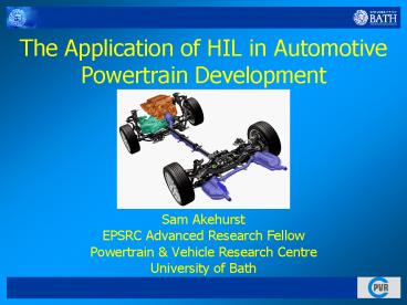
The Application of HIL in Automotive Powertrain Development - PowerPoint PPT Presentation
1 / 29
Title: The Application of HIL in Automotive Powertrain Development
1
The Application of HIL in Automotive Powertrain
Development
- Sam Akehurst
- EPSRC Advanced Research Fellow
- Powertrain Vehicle Research Centre
- University of Bath
2
Presentation Outline
Lean Powertrain Development
- What is a Powertrain?
- Lean Powertrain Development
- Project Background, Project aim, Methods
- Where HIL fits in
- HIL Examples
- Virtual calibration
- Virtual components
- Virtual powertrain
- Real Time Engine Modelling
3
What is a Powertrain?
Lean Powertrain Development
- Sub-systems include
- Engine
- Transmission
- After-treatment Systems
- Electronic Control Units (ECU) and Control
Software
4
Powertrain RD - Current Industry Practice
Lean Powertrain Development
- Separate sub-system development process- Little
integration, compromised result - Simulation tools used intensively, but at
sub-system level Little integration to achieve
optimisation - New technologies selected off the shelf- Rarely
optimised for required duty - Lead time to market compromised by multiple
iterations during development
5
Project Aim
Lean Powertrain Development
- To develop an integrated approach to Powertrain
design, performance optimisation and rapid
calibration, through a simulation and model based
philosophy
6
Lean Powertrain Development
Project Aim
Realism
Vehicle Test
Rolling Road
Advanced Engine Test
Basic Engine Test
Powertrain Simulation
Cost Complexity
7
Emerging Technology Issues
Lean Powertrain Development
- Product Cost
- Development cost
- Over Specification, Technology Redundancy
- Control Calibration
- Complexity
- Reliability
- Development time
- Cost and time to market
- Optimisation!
8
Software Hardware Implementation
RTW
GAs
Matlab
MBC
Optimisation Tools
Simulink
Virtual
Engine
Calibration
Vehicle Transmission
Control
HIL
Reality
Powertrain
9
Specific HIL Projects
- Desktop Powertrain Calibration
- Prototype Component Emulation
- Turbocharging/ Air Handling
- Advanced Transmission Control and Optimisation
10
Desktop Powertrain Calibration
- Virtual engine model interacting with production
ECU - Allows rapid calibration of production ECU for
new engine/hardware combinations - Low cost, reduces expensive facility and
experimental time - Can be linked to optimisation routines and
standard vehicle manoeuvres to develop improved
vehicle performance at an early stage in product
development - New control strategies can be developed if
existing strategy is identified as insufficient - Before expensive mistakes are made
- Software approach allows analysis of
non-measurable or hard to measure variables on
engine
11
Engine Loom Interface
PRODUCTION ECU
12
Engine Loom Interface
Production Engine Loom
ECU Breakout
ECU Calibration Tool interface Optimisation
tools
Production ECU
dSPACE HIL Simulator Associated Breakout
13
Virtual Prototyping New Hardware
- Software based simulation of prototype hardware
- turbocharger performance characteristics
- Novel emulating hardware interacts with real
world engine - Combustion Air Handling Unit (CAHU) and Exhaust
Back Pressure Valve (EBP)
14
Engine Test Facility
15
Hardware - Current Engine Turbo Schematic
MASS AIR FLOW
(used as comparator to CAHU)
Tboost
INTAKE
pboost
EXHAUST
Pdownpipe
pback
Texhaust
Tpre-valve
(TURBO SHAFT)
16
Hardware CAHU Schematic
MASS AIR FLOW
CHARGE AIR HANDLING UNIT
Tboost
INTAKE
IN-CYLINDER PRESSURE MEASUREMENT
pboost
INDUSTRIAL COMPRESSOR
EXHAUST
Pdownpipe
pback
BOOST DRAIN VALVE
Tpre-valve
Texhaust
CP CADET Control Data Acquisition
System (Includes Safety)
BACK PRESSURE VALVE
TURBO MODEL on dSPACE Platform
17
Air Handling System Emulation
- Reverse Engineering
- Turbocharger characteristics can be derived from
engine performance requirements - Concurrent development of control strategies and
interactions with other engine systems - Emulating system can describe many iterations of
prototype hardware - Turbocharger, supercharger, electric assist
systems
18
Hardware Turbo Model
- Turbo model is dependant upon the phase of the
project- - Phase 1 Simple look up tables in Simulink
turbine and compressor performance maps. Model of
shaft torque balance. Simulate existing
turbocharger - Phase 2 Simulation of small HP turbine and how it
interacts with existing turbocharger (pulsation
effects) - Phase 3 Simulation of full two stage
turbochargers and superchargers- Torque load
applied to engine by dynamometer
19
Complete Powertrain Testing
- Virtual Vehicle and Engine
- Real world hardware
- transmission and transmission control systems
- Model set-points and feedback signals transmitted
on CAN bus to dyno control system - Inverted model of dyno response
20
Complete Powertrain Emulation
21
Complete Powertrain Emulation
ATI Vision Calibration Tool
Real Time Models, Driver Inverse Response Model
of E-machines
CAN BUS COMMS
Matlab MBC and Optimisation Tools
Output Motor Emulates Vehicle
Input Motor Emulates Engine
CP CADET Control Data Acquisition
System (Includes Safety)
Real Hardware is Transmission and control systems
Drive Cabinets/Common DC bus
22
Real Time Engine Modelling
- Generally a compromise
- Speed of execution vs. model fidelity
- Range of Models Available
- Crank angle resolved (highest fidelity)
- Mean Value (resolved once per engine cycle)
- Response Surface Engine models
23
Real Time Engine Modelling
- Crank Angle or Time based simulation?
- Resolve to crank angle for cylinders
- Mean value model for manifolds/ gas dynamics
- Pre calculate as much as possible
- Populate look-up tables where possible
- Model one cylinder and phase shift others
- Analytical models
- Identify areas of importance for chosen work
- Statistical models derived from offline data fits
(experimental or code generated) - Polynomials
- Multidimensional
24
Response Surface Engine Models
25
Software - Ricardo WAVE
AMBIENT PRESSURE TEMP
AMBIENT PRESSURE TEMP
EXHAUST DOWNPIPE THERMOCOUPLE
MAF SENSOR
JUNCTION
COMPRESSOR
INJECTOR
CYLINDER
EXHAUST
EGR SENSOR
INTERCOOLER
VGT ACTUATOR
TURBINE
DUCT
ORIFICE
INTAKE
EGR ACTUATOR
26
Software Model Based Calibration
SIMULINK BLOCK CREATED FROM MODEL IN SINGLE MOUSE
CLICK
27
Software Calibration Generation
28
Viewing Trade-Offs and Finding Optima
29
Any Questions?


