Basic Setup to Use Vera - PowerPoint PPT Presentation
1 / 18
Title:
Basic Setup to Use Vera
Description:
Making a testbench for an adder module. First, invoke the template generator ... The Interface File (adder.if.vrh) Defines the interface beween the DUT and ... – PowerPoint PPT presentation
Number of Views:68
Avg rating:3.0/5.0
Title: Basic Setup to Use Vera
1
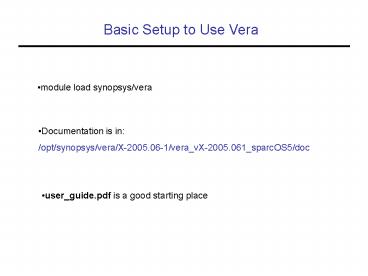
Basic Setup to Use Vera
- module load synopsys/vera
- Documentation is in
- /opt/synopsys/vera/X-2005.06-1/vera_vX-2005.061_sp
arcOS5/doc
- user_guide.pdf is a good starting place
2
The Standard Vera Testbench Structure
- There will be files for each block
3
Running Vera
module adder(in0, in1, out0, clk) input70
in0, in1 input clk output80 out0 reg80
out0 always_at_(posedge clk) begin out0 lt in0
in1 end endmodule
- Making a testbench for an adder module
- First, invoke the template generator
gt vera -tem -t adder -c clk adder.v
4
Template Generator Results
- The Interface File (adder.if.vrh)
- Defines the interface beween the DUT and the Vera
program
// adder.if.vrh ifndef INC_ADDER_IF_VRH define
INC_ADDER_IF_VRH interface adder output 70
in0 OUTPUT_EDGE OUTPUT_SKEW output 70 in1
OUTPUT_EDGE OUTPUT_SKEW input 80 out0
INPUT_EDGE -1 input clk CLOCK //end of
interface adder endif
- Modify if additional signals need to be
controlled/observed
5
More Template Generator Results
- The test_top File (adder.test_top.v)
- Instantiates top-level testbench (Vera shell
DUT)
vera_shell vshell( //Vera shell
file. .SystemClock(SystemClock), .adder_in0
(in0), .adder_in1 (in1), .adder_out0
(out0), .adder_clk (clk),) ifdef emu /DUT is
in emulator, so not instantiated
here/ else adder dut( .in0 (in0), .in1
(in1), .out0 (out0), .clk (clk),) endif
6
More Template Generator Results
- The Vera File (adder.vr.tmp -gt adder.vr)
- Contains the Vera code which describes the
testbench
define OUTPUT_EDGE PHOLD define OUTPUT_SKEW
1 define INPUT_EDGE PSAMPLE include
ltvera_defines.vrhgt // define any interfaces, and
verilog_node here include "adder.if.vrh program
adder_test // Here is the main Vera code
7
More Template Generator Results
- The Vera Shell File (adder_shell.v)
- Verilog code which communicates with the Vera
testbench
Module vera_shell( SystemClock, adder_in0, adde
r_in1, adder_out0, adder_clk ) input
SystemClock output 70 adder_in0 output 70
adder_in1 input 80 adder_out0 inout
adder_clk wire SystemClock // Other components
of this file are not listed here
8
Running Vera, Remaining Steps
- Compile the adder.vr file
vera -cmp -vlog adder.vr
- Create the executable
vcs -vera adder.v adder_shell.v adder.test_top.v
- Run the simulation
simv vera_loadadder.vro
9
Running Vera, The Big Picture
10
Randomization in Vera
- random() returns a random integer
(urandom,random_range, rand_poisson, etc.) - randomize() method built into all classes will
randomly fill all rand properties of an object
class Foo rand integer x class Bar rand
integer y program main Foo foo
new() Bar bar new() integer z void
foo.randomize() void bar.randomize()
- randomize() calls itself recursively on attribute
classes
11
Random Instruction Execution
- randcase specifies a block of statements, one of
which is executed randomly
randcase weight1 statement1 weight2
statement2 ... weightN statementN
randcase 10 i1 20 i2 50 i3
12
Constraint Based Randomization
- constraints are parts of a class, just like
functions, tasks, and properties (attributes) - Constraints define a relationship between
variables, at least one of which should be random
class Bus rand reg150 addr rand reg310
data constraint word_align addr10
2b0
13
Randomize with Constraints
- Each call to randomize fills new random data into
each rand property according to the constraints
of the class
program test Bus bus new repeat
(50) integer result bus.randomize() if
(result OK) printf("addr 16h data
32h\n ,bus.addr, bus.data) else printf(
"Randomization failed.\n")
14
Random Sequence Generation
- A (context free) language is defined as a set of
production rules - Production rules are selected randomly when there
is choice
randseq (production_name) production_definition1
production_definition2 ... production_defini
tionN
15
Random Sequence Generation
- Non-terminals are replaced using production rule
- Generation is complete when only terminals remain
Production rule example
All possible sentences
main top middle bottom top add dec middle
popf pushf bottom mov
add popf mov add pushf mov dec popf mov dec pushf
mov
- Great for generating instruction sequnces
- Weights can be added
top (2) add (1) dec
16
Functional Coverage
- You may want to keep track of how many times a
particular event occurs during simulation - ex. How often is x1? Does y ever become 0? etc
- A coverage_group defines the interesting events
that you want to keep track of
coverage_group CovGroup sample_event _at_
(posedge CLOCK) sample var1, ifc.sig1 sample
s_exp(var1 var2)
program covTest integer var1, var2 CovGroup
cg new()
17
Coverage Bins
- To fully define a coverage group, you must know
what signal state and transitions you want to
count
coverage_group CovGroup sample_event _at_
(posedge CLOCK) sample var1, ifc.sig1 sample
s_exp(var1 var2)
- Var1 is sampled, but what values am I interested
in? - State bins and transition bins define the values
you want to count
18
User-Defined Coverage Bins
coverage_group MyCov () sample_event _at_
(posedge clock) sample port_number state
s0(07) state s1(815) trans
t1("s0"-gt"s1")
- s0 is values 0-7
- s1 is values 8-15
- t1 is a transition from s0 to s1


