
13th Lecture 6' Future Processors to use CoarseGrain Parallelism PowerPoint PPT Presentation
1 / 30
Title: 13th Lecture 6' Future Processors to use CoarseGrain Parallelism
1
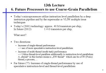
13th Lecture6. Future Processors to use
Coarse-Grain Parallelism
- Todays microprocessors utilize instruction level
parallelism by a deep instruction pipeline and by
the superscalar or VLIW multiple issue techniques - Todays (2001) technology approx. 40 M
transistors per chip, In future (2012)
1.4 G transistors per chip,What next? - Two directions
- Increase of single-thread performance--gt use of
more speculative instruction-level parallelism - Increase of multi-thread (multi-task)
performance--gt Utilize thread-level parallism
additionally to instruction-level parallelismA
thread in this lecture means a HW thread
which can be a SW (Posix) thread, a process, ... - Far future (??) Increase of single-thread
performance by use of speculative
instruction-level and thread-level parallelism
2
5.2 Advanced Superscalar Processors for Billion
Transistor Chips in Year 2005 - Characteristics
- Aggressive speculation, such as a very aggressive
dynamic branch predictor, - a large trace cache,
- very-wide-issue superscalar processing (an issue
width of 16 or 32 instructions per cycle), - a large number of reservation stations to
accommodate 2,000 instructions, - 24 to 48 highly optimized, pipelined functional
units, - sufficient on-chip data cache, and
- sufficient resolution and forwarding logic.
- see Yale N. Patt, Sanjay J. Patel, Marius
Evers, Daniel H. Friendly, Jaret Stark One
Billion Transistors, One Uniprocessor, One Chip.
IEEE Computer, September 1997, pp. 51-57.
3
(No Transcript)
4
Requirements and Solutions
- Delivering optimal instruction bandwidth
requires - a minimal number of empty fetch cycles,
- a very wide (conservatively 16 instructions,
aggressively 32), full issue each cycle, - and a minimal number of cycles in which the
instructions fetched are subsequently discarded. - Consuming this instruction bandwidth requires
- sufficient data supply,
- and sufficient processing resources to handle the
instruction bandwidth. - Suggestions
- an instruction cache system (the I-cache) that
provides for out-of-order fetch (fetch, decode,
and issue in the presence of I-cache misses). - a large Trace cache for providing a logically
contiguous instruction stream, - an aggressive Multi-Hybrid branch predictor
(multiple, separate branch predictors, each tuned
to a different class of branches) with support
for context switching, indirect jumps, and
interference handling.
5
Multi-Hybrid Branch Predictor
- Hybrid predictors comprise several predictors,
each targeting different classes of branches. - Idea each predictor scheme works best for
another branch type. - McFarling already combined two predictors (see
also PowerPC 620, Alpha 21364,...). - As predictors increase in size, they often take
more time to react to changes in a program
(warm-up time). - A hybrid predictor with several components can
solve this problem by using component predictors
with shorter warm-up times while the larger
predictors are warming up. - Examples of predictors with shorter warm-up times
are two-level predictors with shorter histories
as well as smaller dynamic predictors. - The Multi-Hybrid uses a set of selection counters
for each entry in the branch target buffer, in
the trace cache, or in a similar structure,
keeping track of the predictor currently most
accurate for each branch and then using the
prediction from that predictor for that branch.
6
Instruction supply and out-of-order fetch
- An in-order fetch processor, upon encountering a
trace cache miss, waits until the miss is
serviced before fetching any new segments. - But an out-of-order fetch processor temporarily
ignores the segment associated with the miss,
attempting to fetch, decode, and issue the
segments that follow it. - After the miss has been serviced, the processor
decodes and issues the ignored segment. - Higher performance can be achieved by fetching
instructions thatin terms of a dynamic
instruction traceappear after a mispredicted
branch, but are not control-dependent upon that
branch. - In the event of a mispredict, only instructions
control-dependent on the mispredicted branch are
discarded. - Out-of-order fetch provides a way to fetch
control-independent instructions.
7
Data Supply
- A 16-wide-issue processor will need to execute
about eight loads/stores per cycle. - The primary design goal of the data-cache
hierarchy is to provide the necessary bandwidth
to support eight loads/stores per cycle. - The size of a single, monolithic, multi-ported,
first-level data cache would likely be so large
that it would jeopardize the cycle time. - Because of this, we expect the first-level data
cache to be replicated to provide the required
ports. - Further features of the data supply system
- A bigger, second-level data cache with less port
requirements. - Data prefetching.
- Processors will predict the addresses of loads,
allowing loads to be executed before the
computation of operands needed for their address
calculation. - Processors will predict dependencies between
loads and stores, allowing them to predict that a
load is always dependent on some older store.
8
Execution Core
- If the fetch engine is providing 16 to 32
instructions per cycle, then the execution core
must consume instructions just as rapidly. - To avoid unnecessary delays due to false
dependencies, logical registers must be renamed. - To compensate for the delays imposed by the true
data dependencies, instructions must be executed
out of order. - Patt et al. envision an execution core
comprising 24 to 48 functional units supplied
with instructions from large reservation stations
and having a total storage capacity of 2,000 or
more instructions. - Functional units will be partitioned into
clusters of three to five units. Each cluster
will maintain an individual register file. Each
functional unit has its own reservation station. - Instruction scheduling will be done in stages.
9
Conclusions (so far)
- Patt et al. argue that the highest performance
computing system (when one billion transistor
chips are available) will contain on each
processor chip a single processor. - All this makes sense, however, only
- if CAD tools can be improved to design such chips
- if algorithms and compilers can be redesigned to
take advantage of such powerful dynamically
scheduled engines.
10
6. Future Processors to use Coarse-Grain
Parallelism
- Chip multiprocessors (CMPs) or multiprocessor
chips - integrate two or more complete processors on a
single chip, - every functional unit of a processor is
duplicated - Simultaneous multithreaded processors (SMPs)
- store multiple contexts in different register
sets on the chip, - the functional units are multiplexed between the
threads, - instructions of different contexts are
simultaneously executed
11
6.2 Chip Multiprocessors (CMPs)6.2.1 Principal
Chip Multiprocessor Alternatives
- symmetric multiprocessor (SMP),
- distributed shared memory multiprocessor (DSM),
- message-passing shared-nothing multiprocessor.
12
Organizational principles of multiprocessors
13
Typical SMP
14
Shared memory candidates for CMPs
Shared-main memory and
shared-secondary cache
15
Shared memory candidates for CMPs
and shared-primary cache
16
Grain-levels for CMPs
- multiple processes in parallel
- multiple threads from a single application ?
implies a common address space for all threads - extracting threads of control dynamically from a
single instruction stream - ? see last chapter, multiscalar, trace
processors, ...
17
Texas Instruments TMS320C80 Multimedia Video
Processor
18
Hydra A Single-Chip Multiprocessor
19
Conclusions on CMP
- Usually, a CMP will feature
- separate L1 I-cache and D-cache per on-chip CPU
- and an optional unified L2 cache.
- If the CPUs always execute threads of the same
process, the L2 cache organization will be
simplified, because different processes do not
have to be distinguished. - Recently announced commercial processors with CMP
hardware - IBM Power4 processor with 2 processor on a single
die - Sun MAJC5200 two processor on a die (each
processor a 4-threaded block-interleaving VLIW)
20
6.3 Multithreaded Processors
- Aim Latency tolerance
- What is the problem?
- Load access latencies measured on an Alpha Server
4100 SMP with four 300 MHz Alpha 21164 processors
are - 7 cycles for a primary cache miss which hits in
the on-chip L2 cache of the 21164 processor, - 21 cycles for a L2 cache miss which hits in the
L3 (board-level) cache, - 80 cycles for a miss that is served by the
memory, and - 125 cycles for a dirty miss, i.e., a miss that
has to be served from another processor's cache
memory. - Multithreaded processors are able to bridge
latencies by switching to another thread of
control - in contrast to chip multiprocessors.
21
Multithreaded Processors
- Multithreading
- Provide several program counters registers (and
usually several register sets) on chip - Fast context switching by switching to another
thread of control
22
Approaches of Multithreaded Processors
- Cycle-by-cycle interleaving
- An instruction of another thread is fetched and
fed into the execution pipeline at each processor
cycle. - Block-interleaving
- The instructions of a thread are executed
successively until an event occurs that may cause
latency. This event induces a context switch. - Simultaneous multithreading
- Instructions are simultaneously issued from
multiple threads to the FUs of a superscalar
processor. - combines a wide issue superscalar instruction
issue with multithreading.
23
Comparision of Multithreading with
Non-Multithreading Approaches
- (a) single-threaded scalar
- (b) cycle-by-cycle interleaving multithreaded
scalar - (c) block interleaving multithreaded scalar
24
Comparision of Multithreading with
Non-Multithreading Approaches
)
s
e
l
c
y
c
r
o
s
s
e
c
o
r
p
(
e
m
i
T
Issue slots
(a)
- (a) superscalar (c) cycle-by-cycle
interleaving - (b) VLIW (d) cycle-by-cycle interleaving VLIW
25
Comparison of Multithreading withNon-Multithreadi
ng
- simultaneous multithreading (SMT) and
chip multiprocessor (CMP)
26
6.3.3 Cycle-by-Cycle Interleaving
- the processor switches to a different thread
after each instruction fetch - pipeline hazards cannot arise and the processor
pipeline can be easily built without the
necessity of complex forwarding paths - context-switching overhead is zero cycles
- memory latency is tolerated by not scheduling a
thread until the memory transaction has completed
- requires at least as many threads as pipeline
stages in the processor - degrading the single-thread performance if not
enough threads are present
27
Cycle-by-Cycle Interleaving- Improving
single-thread performance
- The dependence look-ahead technique adds several
bits to each instruction format in the ISA. - Scheduler feeds non data or control dependent
instructions of the same thread successively into
the pipeline. - The interleaving technique proposed by Laudon et
al. adds caching and full pipeline interlocks to
the cycle-by-cycle interleaving approach.
28
Tera MTA
- cycle-by-cycle interleaving technique
- employs the dependence-look-ahead technique
- VLIW ISA (3-issue)
- The processor switches context every cycle (3 ns
cycle period) among as many as 128 distinct
threads, thereby hiding up to 128 cycles (384 ns)
of memory latency.? 128 register sets
29
Tera Processing Element
30
Tera MTA
Recommended
