Computerized Data Acquisition Systems PowerPoint PPT Presentation
1 / 20
Title: Computerized Data Acquisition Systems
1
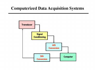
Computerized Data Acquisition Systems
Transducer
Signal Conditioning
A/D Conversion
D/A Conversion
Computer
2
Typical PC-based DAQS
- Data Acquisition
- Data saving
- Data manipulation and display
- Process control by making use of the results
3
SCX Signal Conditioning
- Amplification
- Attenuation
- Multiplexing
- Filtering
- Excitation
- Linearization
4
Signal Conditioning
- Amplification
- Amplify low level signal
- Max of amplified signal equals to max input range
of the analog to digital converter (ADC) - Attenuation
- Reduce high-level signals
- Multiplexing
- Measure multiple signals
- Filtering
- Remove undesirable frequency information
- Noise filter
- Antialiasing filter
- Excitation
- Generate excitation for some transducers strain
gauge - Linearization
- Account for nonlinear response to change in
phenomena being measured, thermocouples
5
Signal conditioning board
SC-2345
SC-2075
CA-1000
SCB-68
6
Plug-In Data Acquisition Boards
- Key Benefits
- Lowest cost
- Large selection to choose from
- Established platform
7
Example of Computer DAQ System
DAQ Board
8
Inside the Case of a Computer
- It contains a system board (mother board). This
board hosts most of the circuits connecting - CPU,
- memory,
- I/O ports.
- buses,
- storage
- Power supplier
9
Sampling Concepts
- Sampling Rate
- How often the AD conversion take place
- Multiplexing
- A common technique to measure several signals
with a single ADC
10
Aliasing
11
Representing Numbers in Computers
Everyday life Decimal
Computers Binary
One-to-one correspondence
A bit has bistable states on (1) and off (0) 8
bits 1 byte
01011100 0?20 0?21 1?22 1?23 1?24
0?25 1?26 0?2792
12
Representing Negative Numbers
MSB is 0 for positive numbers MSB is 1 for
negative numbers
2s complement
- Convert the integer to binary as if it were
positive - Invert all of the bits
- Add 1 least significant bit to produce the final
result
13
Major DAQ Components
- Multiplexers (MUX) multi-channel handling
- Analog-to-digital converters
- Digital-to-analog converters
- Simultaneous sample-and-hold subsystems
14
Basics of A/D Converters
- The output has 2N possible values quantization
- N number of bits.
- Characteristics
- N determines the resolution of the output
- Input range unipolar and bipolar
- Conversion speed
15
Data Acquisition Terminology
- Resolution - Determines how much different
voltage changes can be measured - Higher resolution ? more precise representation
of signal - Range - minimum and maximum voltages
- Smaller range ? more precise representation of
signal - Gain - Amplifies or attenuates signal for best
fit in range - Code width (LSB) smallest detectable change in
voltage depend on range, resolution, and gain
16
Resolution Error
Input resolution error Example A 12-bit A/D
converter has an analog input range of -10 to 10
V. Find the resolution error of the converter for
the analog input.
17
Single-slope integrating A/D Converter
Analog input voltage
voltage
Integrator voltage
Input range
Time (counter)
Counter
Integrator
Comparator
18
Successive-approximation converters
- Employ an interval-halving rule
- Example
- An 8-bit AD unipolar successive-approximation
converter has an input range of 0 to 5V. An
analog voltage of 3.15 V is applied to the input.
Find the analog output
Reference voltage increment (?V) input span/2N
0.01953 V
19
Demo AD Conversion
saturation error
Quantization error
20
D/A Conversion
Convert n-digital binary word into an analog
voltage

