HP 3780A Bit Error Rate Tester BERT PowerPoint PPT Presentation
1 / 1
Title: HP 3780A Bit Error Rate Tester BERT
1
HP 3780A Bit Error Rate Tester (BERT)
Quick Reference Guide
Main Controls and I/O Connectors
I/O Connectors
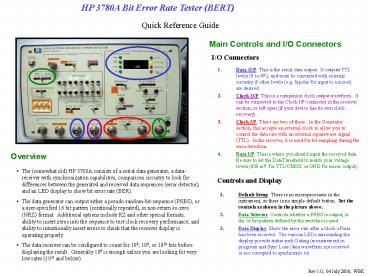
- Data O/P This is the serial data output. It
outputs TTL levels (0 to 4V), and must be
converted with external circuitry if other levels
(e.g. bipolar for input to a mixer) are desired. - Clock O/P This is a companion clock output
waveform. It can be connected to the Clock I/P
connector in the receiver section, or left open
(if your device has its own clock recovery). - Clock I/P There are two of these. In the
Generator section, this accepts an external clock
to allow you to control the data rate with an
external squarewave signal (TTL). In the
receiver, it is used for bit sampling during the
error detection. - Data I/P This is where you should input the
received data. Be sure to set the DataThreshold
to match your voltage levels (600 mV for
TTL/CMOS, or GND for mixer output).
Overview
- The (somewhat old) HP 3780A consists of a serial
data generator, a data-receiver with
synchronization capabilities, comparison
circuitry to look for differences between the
generated and received data sequences (error
detector), and an LED display to show bit error
rate (BER). - The data generator can output either a
pseudo-random-bit-sequence (PRBS), or a
user-specified 16 bit pattern (continually
repeated), in non-return-to-zero (NRZ) format.
Additional options include RZ and other special
formats, ability to insert zeros into the
sequence to test clock recovery performance, and
ability to intentionally insert errors to check
that the receiver display is operating properly. - The data receiver can be configured to count for
106, 108, or 1010 bits before displaying the
result. Generally 106 is enough unless you are
looking for very low rates (10-6 and below).
Controls and Display
- Default Setup There is no microprocessor in the
instrument, so there is no simple default button.
Set the controls as shown in the picture above. - Data Selector Controls whether a PRBS is output,
or the 16 bit pattern defined by the switches is
used. - Data Display Show the error rate after a block
of bits has been received. The various LEDs
surrounding the display provide status such
Gating (measurement in progress) and Sync Loss
(data waveform not received or too corrupted to
synchronize to)
Rev 1.0, 04 July 2006, WBK

