The Fiber Optic - PowerPoint PPT Presentation
1 / 23
Title:
The Fiber Optic
Description:
The Fiber Optic Cable The silica glass of today s optical fibers provides an extremely low loss, high speed path for light pulses Advantages of Optical Fiber ... – PowerPoint PPT presentation
Number of Views:1385
Avg rating:3.0/5.0
Title: The Fiber Optic
1
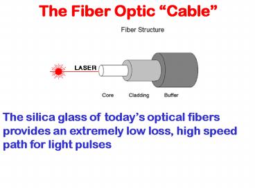
The Fiber Optic Cable
The silica glass of todays optical fibers
provides an extremely low loss, high speed path
for light pulses
2
Advantages of Optical Fiber Systems
- Small Diameter
- Lightweight
- Electrical Immunity
- Safety
- Security
- But MOST Important
- Low Loss
- Wide Bandwidth
3
Bandwidth
The Impact of Lightwave lies Primarily in
its Enormous Bandwidth Capacity
So What is Bandwidth?
Bandwidth is the limit to the transmission
rate Bandwidth is the highways and interstates
Data travels across
4
Bandwidth
The Limit to Transmission Rate
So What is Bandwidth?
At High Frequencies the amplitude of a signal
will decrease as it travels along the media. This
increase in attenuation with increasing frequency
imposes a limit to transmission
1
Ampl. Out Ampl. In
.5
0
Frequency
f3dB
Bandwidth is the range of frequencies over which
the attenuation is less than 50 of the 3 dB point
5
Telephone Digital Voice Channels
Voice Channels Designation Bit Rate
1 single channel 64 kB/sec 24
T1 1.54 MB/sec 96 T2
6.31 MB/sec 672 T3 44.7 MB/sec
Europe and Japan have slightly differing standards
6
Bandwidth
Fiber vs. Coax (Electrical) Systems
Attenuation Through 1 km
0
Fiber (c.1994)
4
Fiber (c.1986)
Attenuation (dB)
8
Coax RGA 19
12
16
.1 1 10
100 1000 10000
100000
Frequency MHz
Lightwave advantage - More Bits per second!
7
The Story of Lightwave
A story of keeping pace with the traffic
demand and transmit (and receive) more data or
Larger Data and Voice Highways across a smaller
medium
MORE BITS PER SECOND FOR LESS !!
8
New International Rates - SONET
SONET Synchronous Optical NETwork
OC Standards OC-1 51.5 Mb/sec OC-3 155.5
Mb/sec OC-12 622 Mb/sec OC-48 2488 Mb/sec
(2.5G) OC-96 4977 Mb/sec OC-192 9953 Mb/sec
(10G) OC-768 out in 2000 (40G)
This standardization has brought on an open and
global market for Fiber Optic suppliers. More
Business for ALL !!!
9
Power Attenuation
- Loss Mechanisms in Glass Fiber
- Absorption in the UV
- Absorption in the IR
- Scattering Loss
- OH Absorption
- Bending Loss
10
Silica Glass Fiber Optic Loss Curve
Attenuation curve for Silicon Glass Fiber shows 3
major wavelength regions at which fiber systems
have been deployed
800 nm (early)
1300 nm 1990s
1500 nm current
Lower attenuation at 1500 nm means gtgtgt Larger
distance between Repeaters
11
Fiber Connections and Splices
12
Start with Fiber
Much of fiber connecting and splicing begins with
MATCHING!!!
13
Connectors
14
Connector Components
Bend Relief Boot
Front Dust Cover
Ferrule
Crimp Ferrule
Connector Body
15
Types of Splices
Fusion Loss loss method for fusing
fiber Sections together. Often loss is Less than
.05 dB. Alignment using An attached microscope
and fibers Are electrically Arc welded until They
melt together or fuse. Production operation
fusing in less Than 30 seconds with all types
of Fiber.
Mechanical Epoxy fibers together in a
mechanical Holder or sleeve. Less expensive
but With higher losses. Some connections With a
matching index gel to reduce Loss.
16
Other Types of Splice Equipment
PM Fusion Splicer
Mechanical Cleaver
Ultrasonic Cleaner
Thermal Stripper
17
Connector and Splice Loss Mechanisms
Lets start with MATCHING!!!
Anytime we mismatch larger diameter core to
smaller we get large losses. Remember 3 dB loss
is half our signal power!!!
18
Connector and Splice Loss Mechanisms
19
Installing Connectors and Fiber
- The Basic Steps
- Cut the cable and strip the fiber to core and
clad - Clean the fiber
- Slide the fiber through the ferrule (1/4 ) and
crimp or epoxy and cure - Anchor the cable to the connector body
- Prepare the fiber face by cleave and polish
- Clean the fiber face
- Inspect the fiber face
- Repeat polish and clean as necessary
- Inspect till complete
20
Inspecting Connectors and Fiber Ends
21
Connector and Splice Loss Testing
Set a reference
Test your connector losses
22
System OTDR Testing
23
System OTDR Testing


